Posts: 13,776
Threads: 580
Joined: Sep 2005
City: Ferdinand
State, Province, Country: Indiana
Phlogiston Wrote:On those filter caps, I usually drill a small hole in the metal stud its self. It is easier than drilling the Bakelite.
Oh, I do as well. But please go back and examine the photos again. The Solar cap is constructed differently from an original stud mounting electrolytic - the entire base, including the threads, is Bakelite. So it called for some rethinking since I did not have another original type stud mounting electrolytic (with insulating washers) in my stash o' stuff.
And if you mean the aluminum rivets that hold the solder terminals in place (upon rethinking, I suspect this is what you meant), I don't have a drill press so I can't always drill through those rivets without causing trouble. My method worked, though - that's all that matters to me. 
--
Ron Ramirez
Ferdinand IN
Posts: 2,118
Threads: 112
Joined: Jun 2010
City: Medford OR (OR what?)
Yes, the rivets. I use a hand drill (cordless) but you must use some never-seize or similar lube. I also use this technique on newer multi section caps, like the ones in the Sabas.
"I just might turn into smoke, but I feel fine"
http://www.russoldradios.com/
Posts: 13,776
Threads: 580
Joined: Sep 2005
City: Ferdinand
State, Province, Country: Indiana
That does make sense.
--
Ron Ramirez
Ferdinand IN
Posts: 13,776
Threads: 580
Joined: Sep 2005
City: Ferdinand
State, Province, Country: Indiana
Oops! 
I realized that I had forgotten to restuff C32, the .01 uF cap in a metal case. So this evening, I took care of that. It was very difficult to get the metal end caps off, but patience and persistence finally paid off. The new cap is sealed in hot glue inside the metal case.
Hopefully tomorrow evening, I'll have time to attach an AC cord and test the tubes.
--
Ron Ramirez
Ferdinand IN
Posts: 13,776
Threads: 580
Joined: Sep 2005
City: Ferdinand
State, Province, Country: Indiana
Tonight, I attached a new cloth covered line cord and found a suitable AC plug in the parts bin.
I also installed two new LED (#46 equivalent) lamps.
I applied power to the chassis with all tubes removed. The dial lit up. No sizzling from the power transformer, or any other unexpected surprises.
Next step was to test the tubes.
When I was finished, I needed four tubes - 6F5, 6J7, 6K7, and 6L7.
I have an RCA 10K1 Magic Brain chassis I had purchased recently. Anyway, it had the tubes I needed - all were original RCA metal - and all were good.  So they went into the T8-14. I'll buy replacements later and put these back into the 10K1 chassis at that time.
Hopefully tomorrow evening...first power up with tubes and speaker.
--
Ron Ramirez
Ferdinand IN
Posts: 205
Threads: 5
Joined: Sep 2005
City: Newark, Ohio
Ron
I never was a fan of metal tubes, but through the years I have accumulated many. I can dig through the box I have of them and find the ones you need.
I can then send them to you. LMK
Posts: 205
Threads: 5
Joined: Sep 2005
City: Newark, Ohio
Well, I opened my mouth and firmly inserted my foot.
I don't have a 6J7. 
Sorry
Posts: 13,776
Threads: 580
Joined: Sep 2005
City: Ferdinand
State, Province, Country: Indiana
Ed
That's okay. I appreciate your looking. 
I'll send you a PM later regarding other metal tubes.
I never cared much for metal tubes either. But now that I'm restoring some RCA sets which originally used them, I'd like for my RCA sets to have them if possible just for the sake of originality.
--
Ron Ramirez
Ferdinand IN
Posts: 2,118
Threads: 112
Joined: Jun 2010
City: Medford OR (OR what?)
I am always on the lookout for the early metal tubes - with the bump. Almost all of the big manufactures, less Philco, used them in 1935. Many quit in 1936. The earliest ones showed up in 1932. They had stamped labels on the upper tube body until about 1936. I have found most metal tubes (after 1934) to be equal or superior to glass, if for no other reason, shielding.
"I just might turn into smoke, but I feel fine"
http://www.russoldradios.com/
Posts: 816
Threads: 25
Joined: Mar 2014
City: Louisville, KY
" . . . opened my mouth and firmly inserted my foot."

Posts: 13,776
Threads: 580
Joined: Sep 2005
City: Ferdinand
State, Province, Country: Indiana
The moment of truth.
I attached the speaker from my RCA T7-5 only because I was too lazy to detach the T8-14's speaker from its cabinet. (No, I have not yet completed the T7-5. The cabinet needs to be rubbed down, I need to decide which of a few patterns of grille cloth I have here to put into it, and it needs a new dial cover.)
I plugged the T8-14 into my Variac, plugged the Variac into the power strip. Turned on both radio and Variac. Slowly brought up the voltage on the Variac...
and once I reached 110 volts AC...
[Video: https://youtu.be/4sKl5bM2R5M]
It's Alive! 
The video shows me tuning the AM band (Band A), the 49 and 60 meter portions of Band B, and part of Band C so it is a much longer video than I normally post (about 5-1/2 minutes).
The radio badly needs an alignment. One of the first stations I picked up was WJR, Detroit. The trouble is, WJR broadcasts on 760 kc and the T8-14 is receiving it at 63 on the dial. In the video, you will notice that the volume of stations increases considerably above 1000 kc.
Well...probably Friday late afternoon/evening sometime Saturday, I'll do the alignment. This will be my first real trial of my "new" B+K-Precision 4040 signal generator. In preparation for this, tomorrow night I'll wind the coupling coil suggested by John Bartley in my signal generator thread.
Edit: Well, I had better get that new dial scale cut out, drilled, and installed before I attempt an alignment! So the actual alignment may not happen until Saturday.
--
Ron Ramirez
Ferdinand IN
Posts: 13,776
Threads: 580
Joined: Sep 2005
City: Ferdinand
State, Province, Country: Indiana
So I spent my Halloween doing some work to my T8-14.
I began by winding a 100 turn coil onto a toilet paper roll in preparation for giving this set an alignment. The plan is to connect the signal generator to the coil, and then wind a few turns of wire around that winding to couple to the radio.
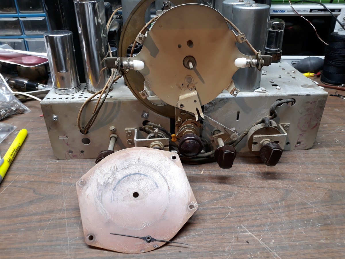
The next job was to remove the old, worn out dial scale.

At first I thought the pointer was held in place by a tiny screw in its center. It certainly appeared as such. But after my tiniest screwdriver would not budge the "screw", I did a quick web search. I found that that isn't a screw at all but merely part of the slotted end of the shaft to which the dial pointer is fastened - it is simply pressed on. So I removed it by carefully pulling it off with a pair of needle nose pliers. Then, after removal of the four push pins (for lack of a better term) which held the dial scale in place, it looked as shown in the photo above.
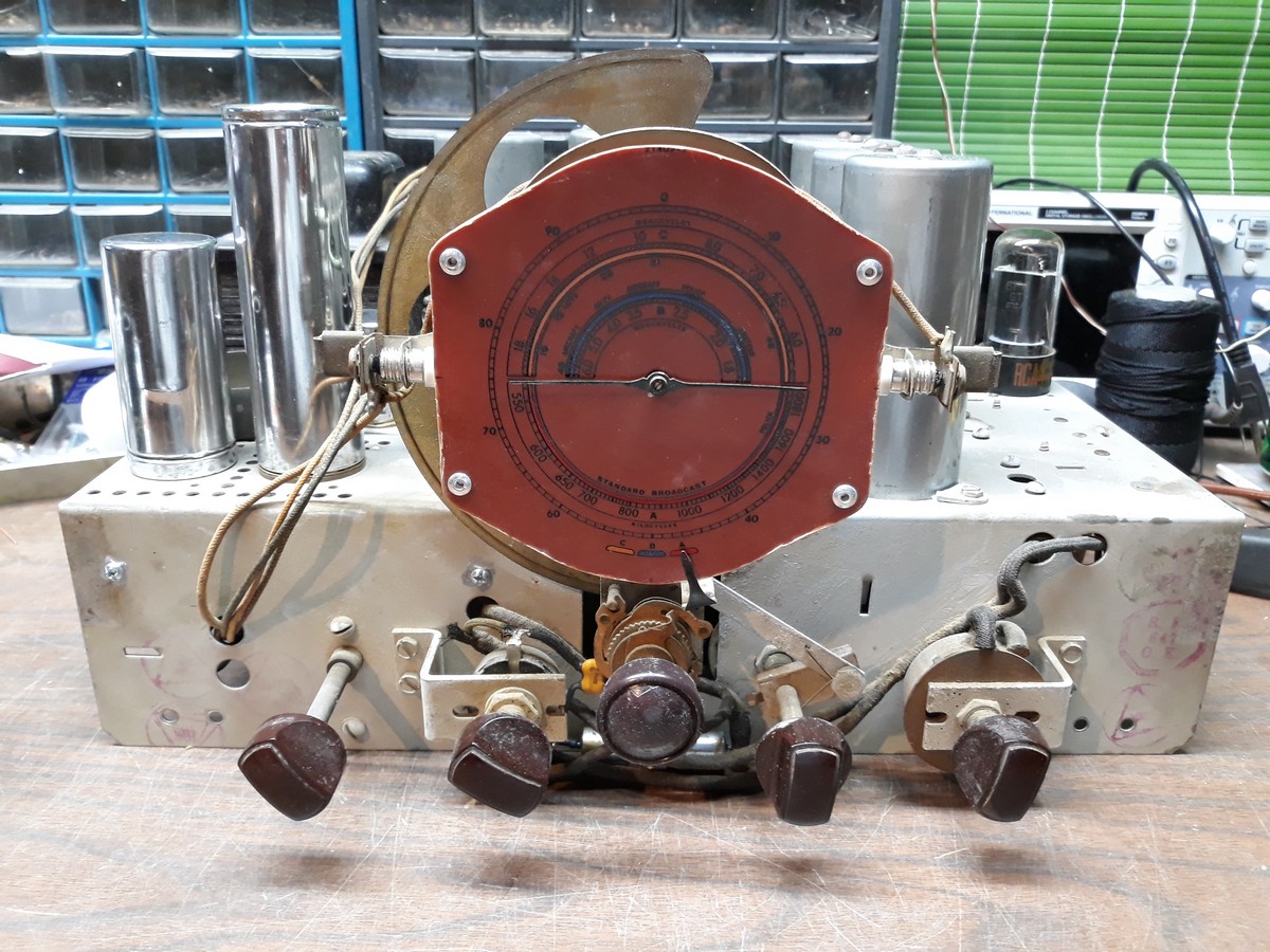
And then, it was time to cut out the new dial scale. Yes, the dial scale I bought was uncut and undrilled. The plastic is very thick and hard also, and was quite hard to cut. But I finally managed to get the job done. Drilling holes was the easy part. Finally, I attached it to the dial face with pop rivets.
Here is how it looks now.

The original dial did not have the 0 to 90 scale around the perimeter of the dial. But the frequencies are the same, so it works for me. I have since learned this is actually the proper scale for a T10-1 or C8-15. Oh well. As I said, the frequencies are exactly the same.
After I took the photo, I noticed that I didn't get all of the dust off the dial scale left from drilling the holes. That was quickly taken care of with a tissue.
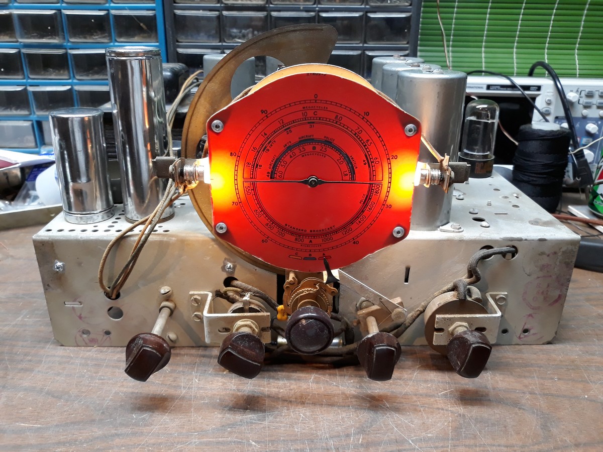
I pulled the rectifier tube, plugged the radio in, and turned it on just to see the dial illuminated.

The photo makes the areas where the dial lamps are located look much "hotter" than they really are. Blame my cellphone camera.
So now it is ready for the alignment which is to come tomorrow evening or Saturday.
--
Ron Ramirez
Ferdinand IN
Posts: 1,824
Threads: 114
Joined: Jul 2014
City: Sneedville, TN
Ron, the scale on my T8-18 was held on by the same kind of little push pin things. I had trouble removing them too. When I put it back I used little 4-40 pan head screws, lock washers, and nuts. They worked fine, and will allow easy removal in the future should it ever be needed.
Posts: 13,776
Threads: 580
Joined: Sep 2005
City: Ferdinand
State, Province, Country: Indiana
Epilog
I aligned the T8-14 late this afternoon using my "new" (to me) B+K - Precision 4040 function generator. In all, it took about 45 minutes. I went over the AM band multiple times since the low end was so far off. And then on band C, I had some trouble finding the fundamental at 18 mc but I finally did so after some tweaking and aligned it properly at 18 mc per the instructions.
I already knew the AM band's alignment was WAY off on the low end of the band. Alignment benefited the IF chain as well as all three bands.
I spent some time listening on all three bands, then stopped for dinner. Afterwards, I put the chassis back in its cabinet and shot the following video. You will notice now that not only are stations coming in close if not right on where they should be, but the low end of the AM band is now just as loud as the high end. And that is how it should be.
[Video: https://youtu.be/0zTt0uEKpvg]
And...that is it for this RCA Victor T8-14. The chassis is complete, aligned, and plays very well on all three bands.
--
Ron Ramirez
Ferdinand IN
Posts: 670
Threads: 11
Joined: Sep 2014
City: Bellmawr, NJ
Very Nice Workmanship,,,Great Job Ron,,,,well Explained,, and greatly detailed,,,,,
Users browsing this thread:
|
|
Recent Posts
|
|
Philco Model 38-7: what caps & resistors do fail typically?
|
| Yep the dim bulb test is OK but I'd definitely replace all those electrolytics before I did it. Since those #47 conden...klondike98 — 09:18 PM |
|
Philco 42-345 Restoration/Repair
|
| The resistor is a 2.2 Meg, it was the last one I hadn't replaced. The broadcast is coming in after replacing it.osanders0311 — 09:09 PM |
|
Philco 42-345 Restoration/Repair
|
| What does the resistor measure? I think it should be 3.3 Meg.
If the oscillator coil has continuity and the resistanc...RodB — 09:03 PM |
|
Philco Model 38-7: what caps & resistors do fail typically?
|
| Good idea to check the coils... then I'll get hold of an incadescent light bulb and see what happens when the unit is sw...Musaeum — 08:49 PM |
|
Philco 42-345 Restoration/Repair
|
| I have that same set, ain't too much shortwave I like anyway.....it is a good AM DX set. PaulPaul Philco322 — 08:32 PM |
|
Philco Model 38-7: what caps & resistors do fail typically?
|
| Welcome to the Phorum, Martin! Open a new thread in Philco Electronic Restoration when you begin working on your 38-7. ...GarySP — 08:28 PM |
|
Philco Model 38-7: what caps & resistors do fail typically?
|
| Welcome to the Phorum!
:wave:
Here's the schematic for that radio from our digital library:
Something to do bef...klondike98 — 08:05 PM |
|
Philco Model 38-7: what caps & resistors do fail typically?
|
| Hi all,
on vacation in Montreal, a friend of mine showed me a Philco Model 38-7 console radio from the 30ies. Mechan...Musaeum — 07:21 PM |
|
Part numbers to model cross
|
| I looked thru the documents and did not see one. Might have missed it though.Jim Dutridge — 07:16 PM |
|
Philco 42-345 Restoration/Repair
|
| Please tell me this was it, I replaced resistor 27 and it's playing on the broadcast band. I am afraid to change the ban...osanders0311 — 06:12 PM |
|
Who's Online
|
There are currently 1075 online users. [Complete List]
» 2 Member(s) | 1073 Guest(s)
|
|
|

|
 
|


![[-] [-]](https://philcoradio.com/phorum/images/bootbb/collapse.png)


