Posts: 13,776
Threads: 580
Joined: Sep 2005
City: Ferdinand
State, Province, Country: Indiana
In August 2018, I acquired an RCA 9T tombstone radio.
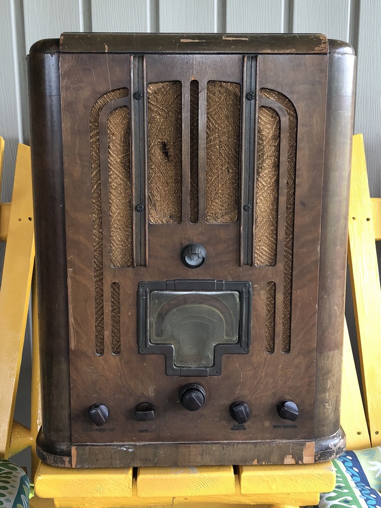
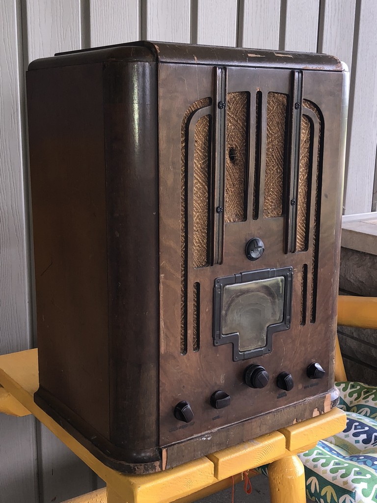
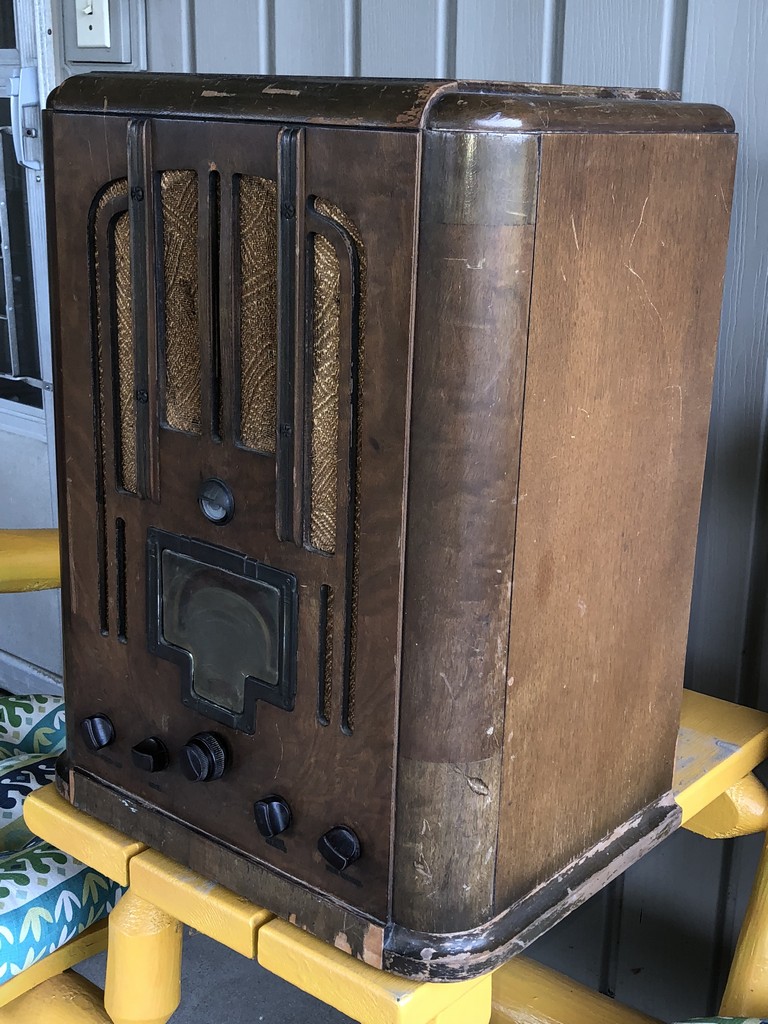
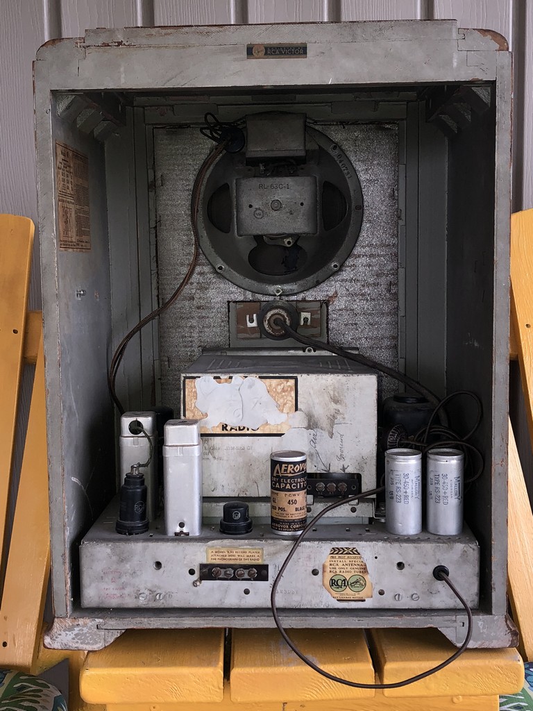
I paid way too much for it but I haven't seen one for sale since, so I guess I'm happy to have it. 
More recently, I picked up an RCA 10K chassis, fairly cheaply. I was considering putting the 10K chassis into the 9T because I really wanted a 10T to begin with - although, I think the 9T cabinet looks better than the 10T cabinet in terms of styling. The 10T/10K has an extra IF stage and high fidelity reception; the 9T does not.
The decision became easy a few weeks ago when I pulled out both chassis and found the 9T chassis had been worked on, but was a hack job. By contrast, the 10K was nearly virgin; only one paper capacitor and one resistor had been replaced, and these repairs had been done decades ago.
The only problem was, both the speaker wiring harness and the tuning eye tube harness had been cut off.
I began working on the 10K chassis anyway.
Removal of the "Magic Brain" was simpler than removing a 1937-38 Philco RF unit. All of the RCA connections terminate in an octal plug.
I did have some trouble with the mechanical end (band switch) of the Magic Brain, but I managed to get everything loose and removed.
--
Ron Ramirez
Ferdinand IN
Posts: 1,824
Threads: 114
Joined: Jul 2014
City: Sneedville, TN
Wow, Ron ! I'm going to enjoy following this one. Take lots of pictures as you work on it.
Posts: 13,776
Threads: 580
Joined: Sep 2005
City: Ferdinand
State, Province, Country: Indiana
So I've been plugging away at the 10K chassis.
Capacitors and resistors were jam packed under the chassis. Since RCA documented this set so well, I decided to just go through and remove all of the paper capacitors, all of the resistors, and replace them all.
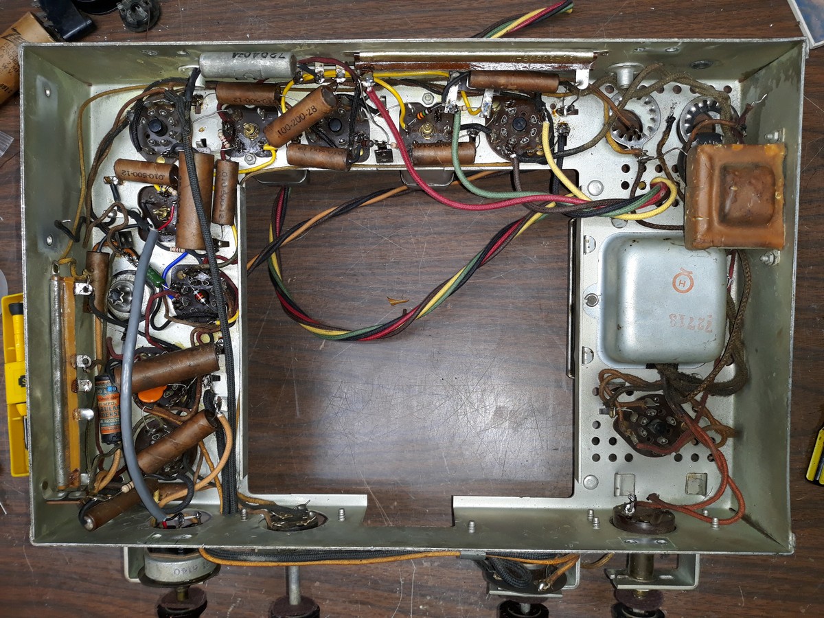
I restuffed all of the paper capacitors, including the single replacement cap, an old Sprague .01 uF unit.
All resistors are new save for the Candohms. I tested both, and both are good. At least they are showing the proper resistances.
I made new wiring harnesses for the speaker cable and for the tuning eye tube.
Then, I turned my attention to the three electrolytics.
I was only able to remove two of the three aluminum electrolytics. Surprisingly, those two still had the boric acid inside in liquid form.
Since both of these were 30 uF, I could not replace with Solen as any such Solen replacement would be way too large for the cans. So I was forced to go with electrolytics. I selected Panasonic replacements.
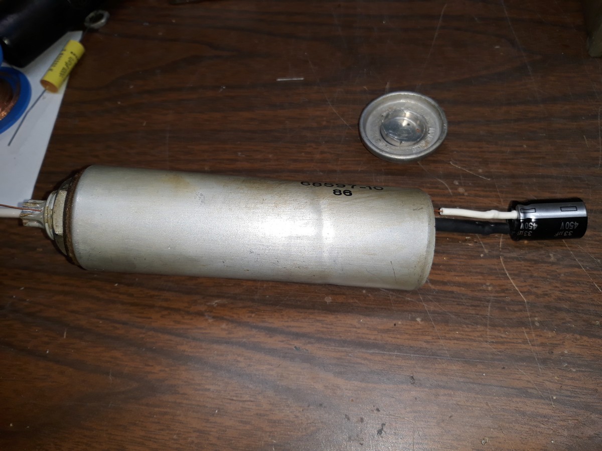
These two are now restuffed, tops glued back on, and I'm waiting for the glue to dry before I polish and reinstall them.
As I had mentioned, I could not remove the 18 uF electrolytic can. The mounting nut would not budge, even after multiple applications of PB Blaster. So I decided to rebuild it in place.
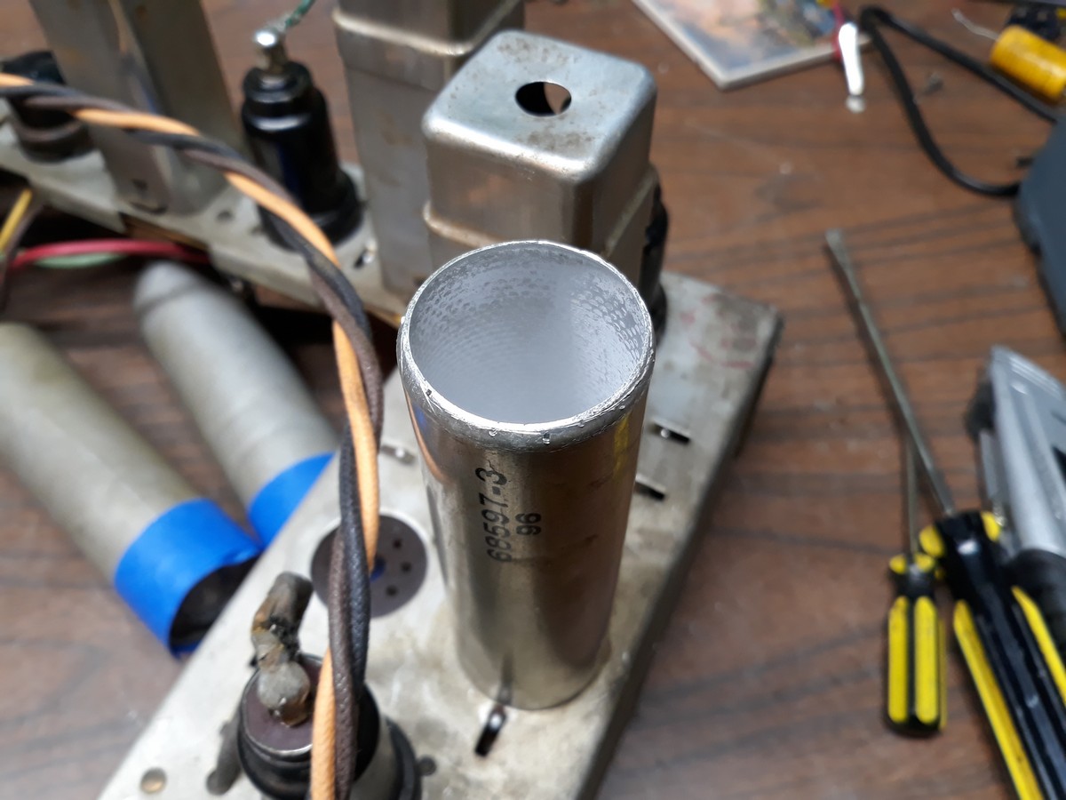
I only got as far tonight as cutting the can open and preparing it for restuffing. Since I used electrolytics for the other two cans, I may just stick another Panasonic electrolytic, 22 uF this time, into this can.
But I've managed to get a little ahead of myself. This past weekend, I pulled the 20 uF, 25V electrolytic out of the chassis. It was encased in a fiber box. I removed the guts and filled most of the cavity with hot glue, leaving a small space for the replacement 22 uF, 50V electrolytic as shown below.
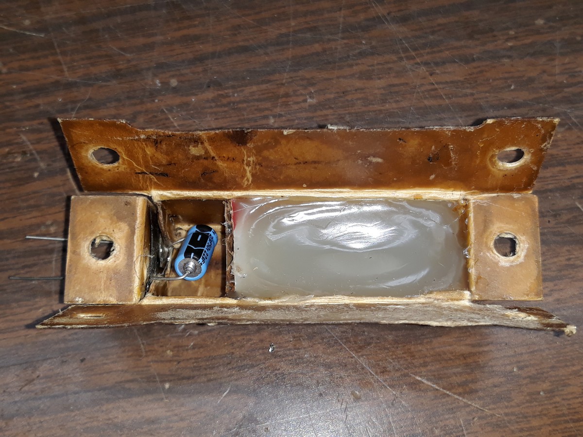
I still need to reinstall this box under the chassis.
I still have more that needs to be done to the main chassis before I can turn my attention to the Magic Brain (RF unit). I've cleaned the fidelity control & switch. I need to do the same to the other controls on the chassis. And there is a rectangular metal can with some capacitors and resistors encased inside which I need to remove, restuff, and reinstall.
--
Ron Ramirez
Ferdinand IN
Posts: 1,887
Threads: 214
Joined: May 2015
City: Seattle
State, Province, Country: WA
You're making fast progress!
One question - how did you remove the tops of the electrolytics?
Posts: 1,824
Threads: 114
Joined: Jul 2014
City: Sneedville, TN
Lots accomplished already. I'm surprised. I look forward to the next installment.
Posts: 13,776
Threads: 580
Joined: Sep 2005
City: Ferdinand
State, Province, Country: Indiana
Nathan
Normally I use a cutting wheel on a Ryobi "Dremel" tool, but this time I decided to try using a box cutter knife instead. It took much longer to cut each one open, but it worked eventually for each can. I did it that way mainly because the two 30 uF electrolytics still had the liquid electrolyte inside, and I didn't want to have that stuff spraying out as I was cutting with the Ryobi.
And since I could not remove the 18 uF electrolytic can, I wanted to be extra careful cutting it open in case it still had liquid inside. Fortunately (in this case), the 18 uF electrolytic was all dried out.
--
Ron Ramirez
Ferdinand IN
Posts: 13,776
Threads: 580
Joined: Sep 2005
City: Ferdinand
State, Province, Country: Indiana
Druid Mike
I've been working on this chassis for a while before I started posting. What you see started two weekends ago. I've been doing a little each evening as well. Very slow work actually.
--
Ron Ramirez
Ferdinand IN
Posts: 3,149
Threads: 56
Joined: Apr 2011
City: Lexington, KY
Looks good Ron 
You guys keep doing these RCA restos and I'm going to wind up dragging one of them home someday 
John KK4ZLF
Lexington, KY
"illegitimis non carborundum"
Posts: 13,776
Threads: 580
Joined: Sep 2005
City: Ferdinand
State, Province, Country: Indiana
Thursday's progress:
I reinstalled C76 (20 uF, 50V) and finished rebuilding C78 in place.
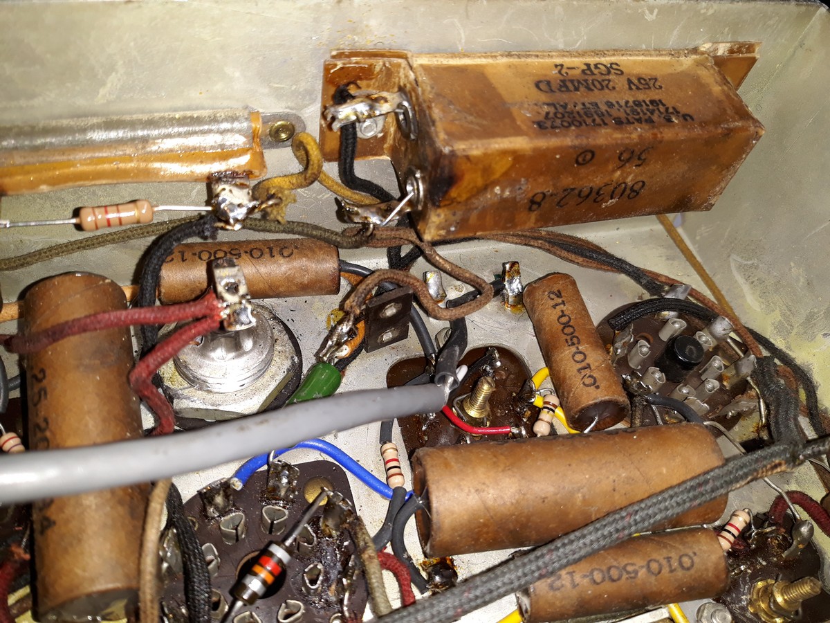
I also polished and reinstalled C73 and C75 (both 30 uF electrolytics).
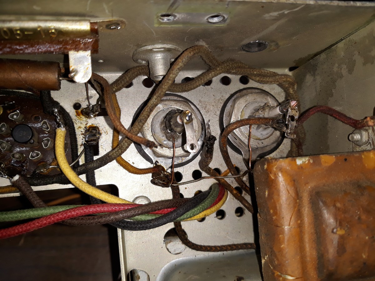
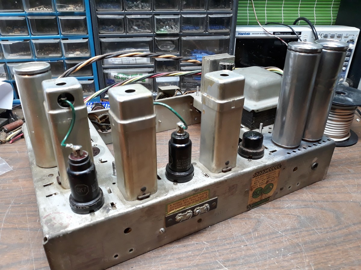
How the chassis looks at this point:
--
Ron Ramirez
Ferdinand IN
Posts: 13,776
Threads: 580
Joined: Sep 2005
City: Ferdinand
State, Province, Country: Indiana
Tonight's (Friday) progress:
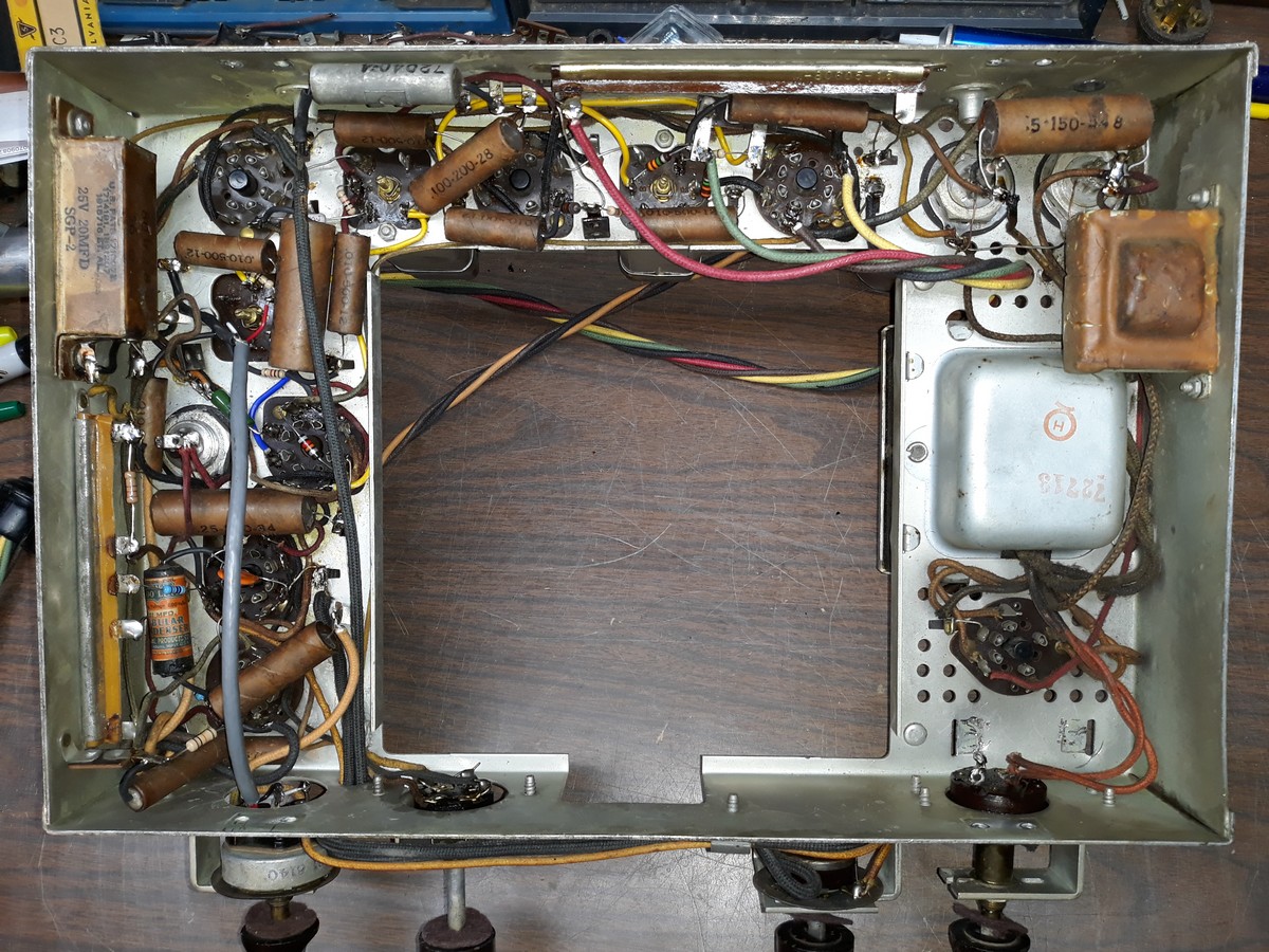
I finished hooking up C73 and C75, and also connected C74 (0.47 uF) across the positive terminals of C73 and C75.
The underside of the chassis now looks like this:
I realized that I needed to remove and restuff the metal can which contains C64, C65, C66, R23, R24, and R26.
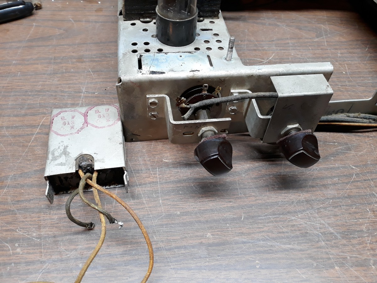
The components are encased in tar. Naturally. I'll have to figure out how I can melt the tar out, with the weather forecast to be rainy this weekend with snow starting Sunday night.
So in the meantime, I set the main chassis aside after cleaning all of the switches and controls, and pulled out the Magic Brain.
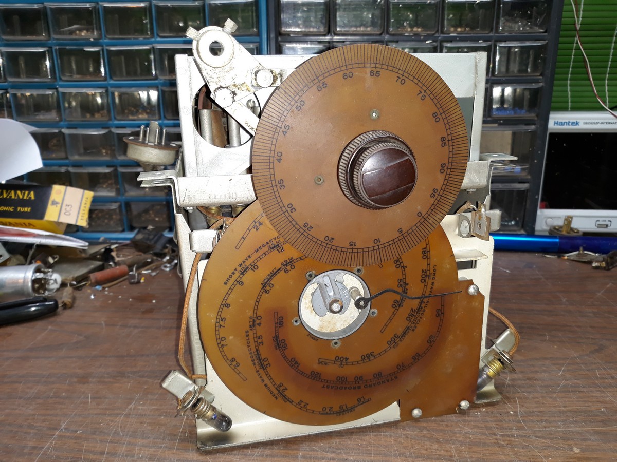
How the top of the "Brain" looks with the cover removed:
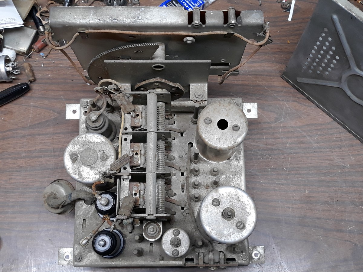
Very dusty.
Now, the underside of the Magic Brain:
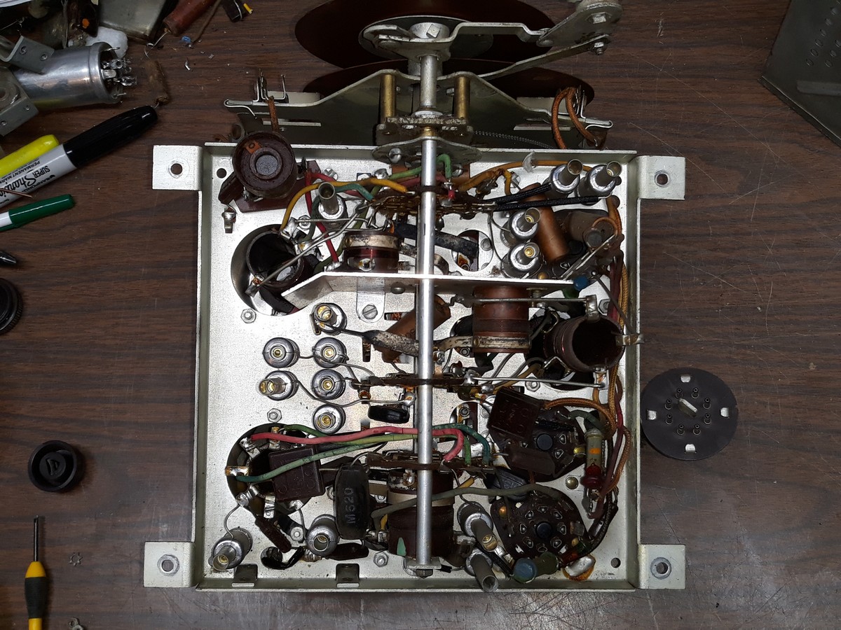
Rubber-covered wires, a couple paper caps, and LOTS of mica caps. Looks like it will be fun to restore. Not.
I decided that I should remove the 0-95 dial scale because it looked as if it could be easily broken.
It was held in place by two set screws.
One of the two set screws promptly broke as soon as I tried to loosen it.
 
The other one loosened just fine.
I had to drill out the broken one, and then carefully get the hub loose so I could remove that dial scale.
I probably should remove the multiple band dial scale as well...as soon as I figure out how to remove it, that is.
--
Ron Ramirez
Ferdinand IN
Posts: 1,409
Threads: 72
Joined: Oct 2007
City: Linn Creek, MO
Super job, Ron.
I to may have to get an RCA. When I was young, we had an RCA console radio. I was too young to know what model it was but from looking at pictures, I think it may have been a C7-6 or C6-2. If I find one of those, I will probably buy it.
Steve
M R Radios C M Tubes
Posts: 13,776
Threads: 580
Joined: Sep 2005
City: Ferdinand
State, Province, Country: Indiana
Thanks Steve.
So this afternoon after returning home from running some errands, I grabbed the metal can with three capacitors and three resistors inside encased in tar, two pairs of pliers, some cardboard, and my heat gun and took all to our detached garage.
It only took five minutes or so until I had the insides softened up enough to remove the old components from the metal can.
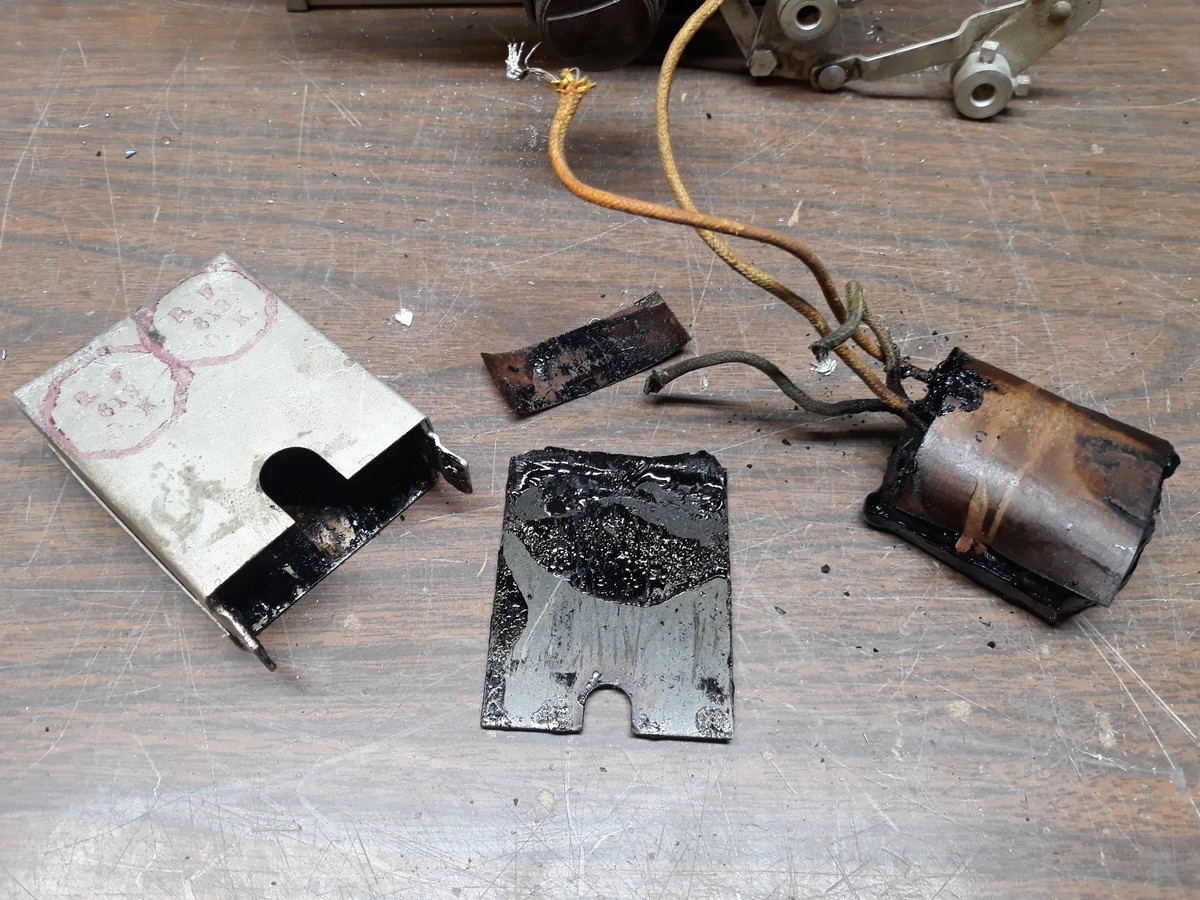
Let's take a look at how all of the components hook up inside the can.
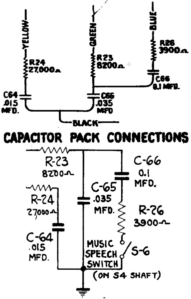
The next step was to replicate the hookup with all new components.
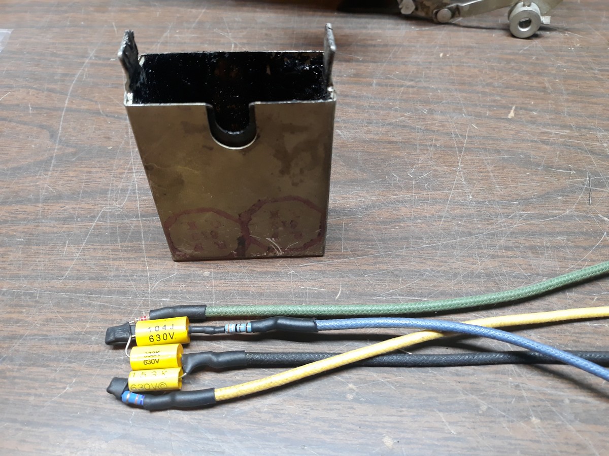
I then prepared the parts for encasing inside the metal can with the use of heat shrink tubing and electrical tape.
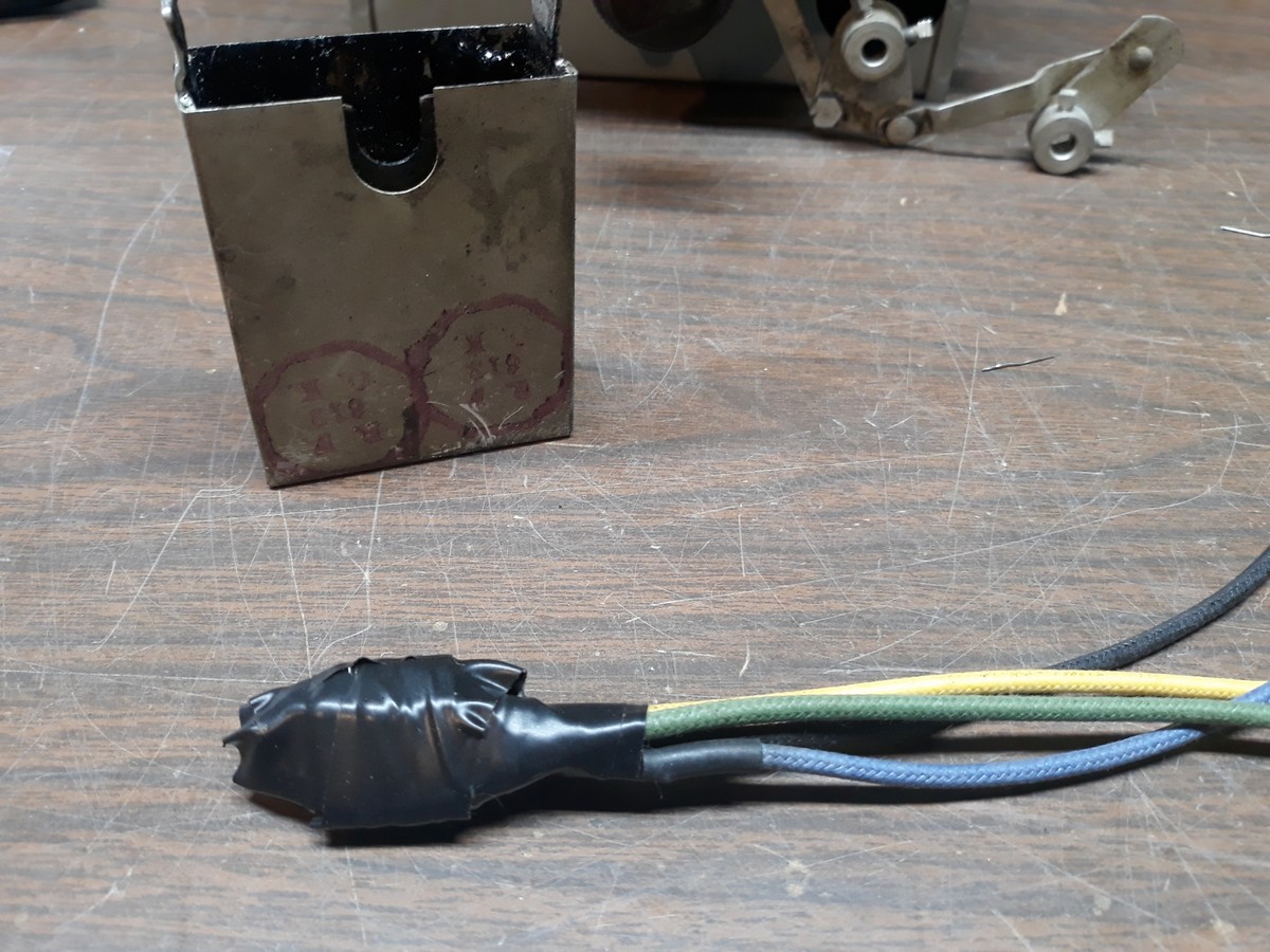
Finally, the new components are placed inside the can and the entire thing is encased in hot glue.
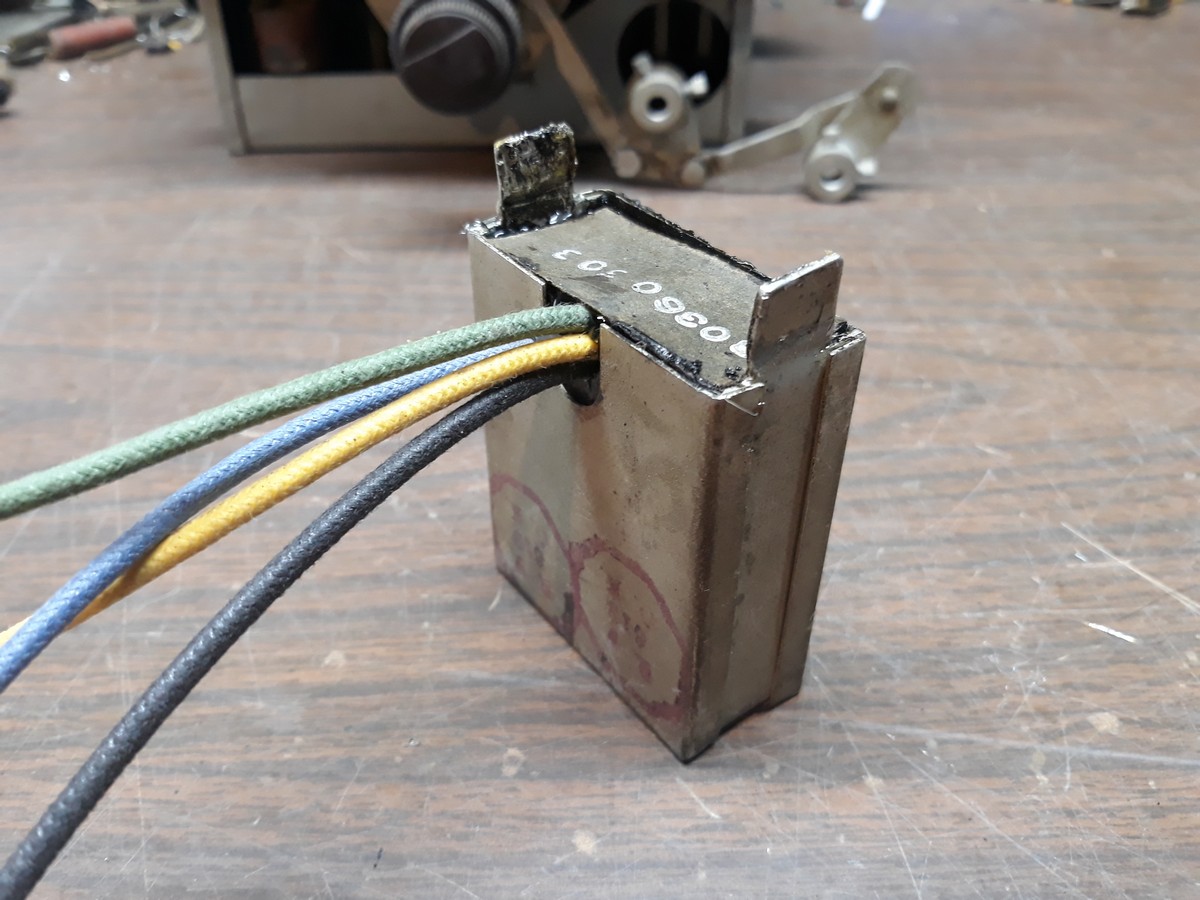
The unit is now ready for reinstallation on the chassis. That may be difficult, as the can mounts to the chassis with those two thick metal "ears" which must be bent over to hold the can in place. But I'll do my best.
--
Ron Ramirez
Ferdinand IN
Posts: 194
Threads: 43
Joined: Jan 2019
City: Brownsville 42210
State, Province, Country: Kentucky
Nice work Ron that set is much more laid out than my C8-19 which is cramped and painful to work on but i am sure you are going to like the performance of this set with the rf stage once you finish the electronics. At least it doesn't need 10 miles of new rubber wire like some sets.
Merry Christmas. Happy Hanuka.
Posts: 13,776
Threads: 580
Joined: Sep 2005
City: Ferdinand
State, Province, Country: Indiana
Today I reinstalled the metal can which contains three capacitors and three resistors.
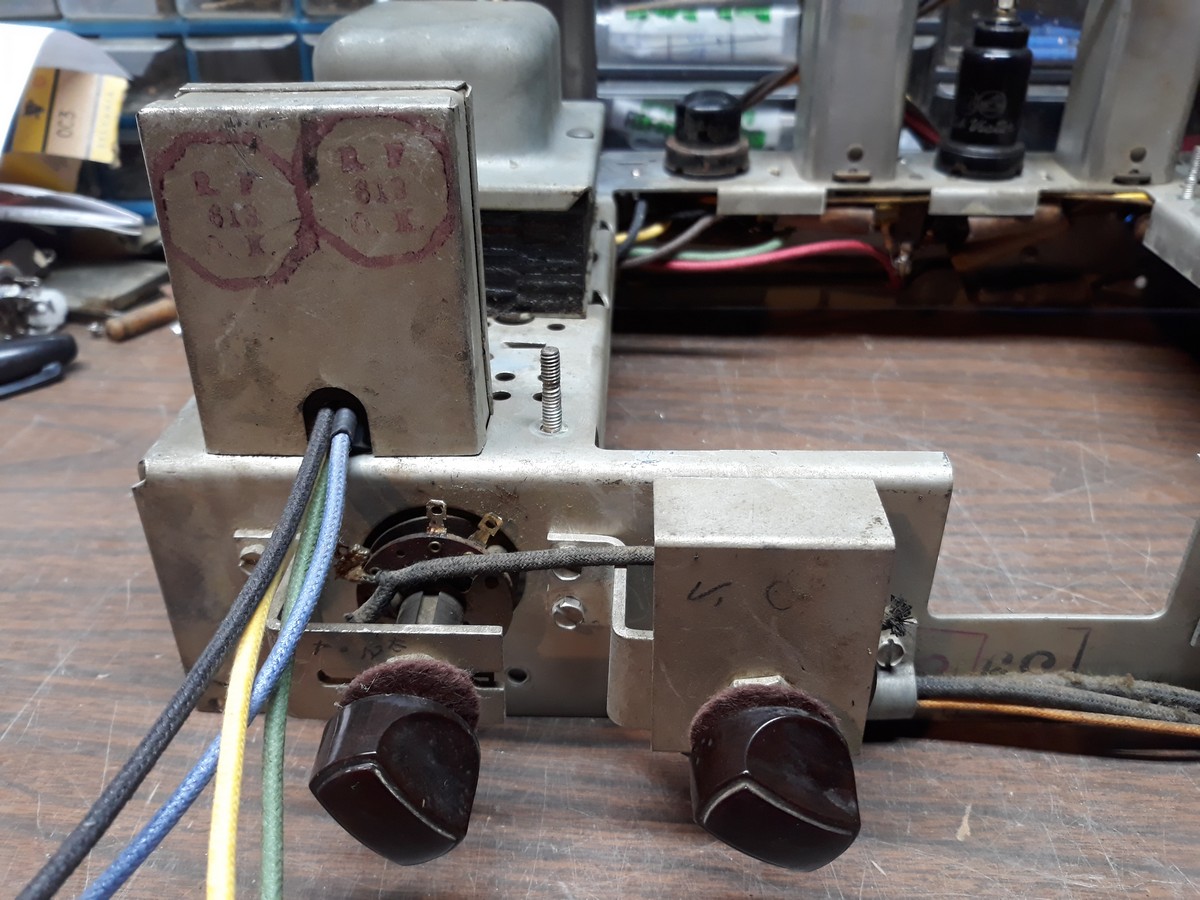
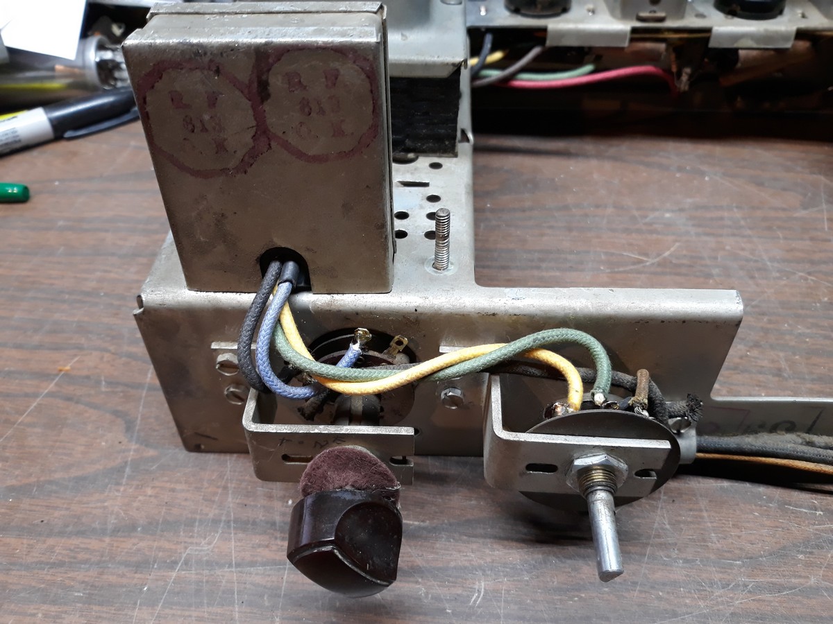
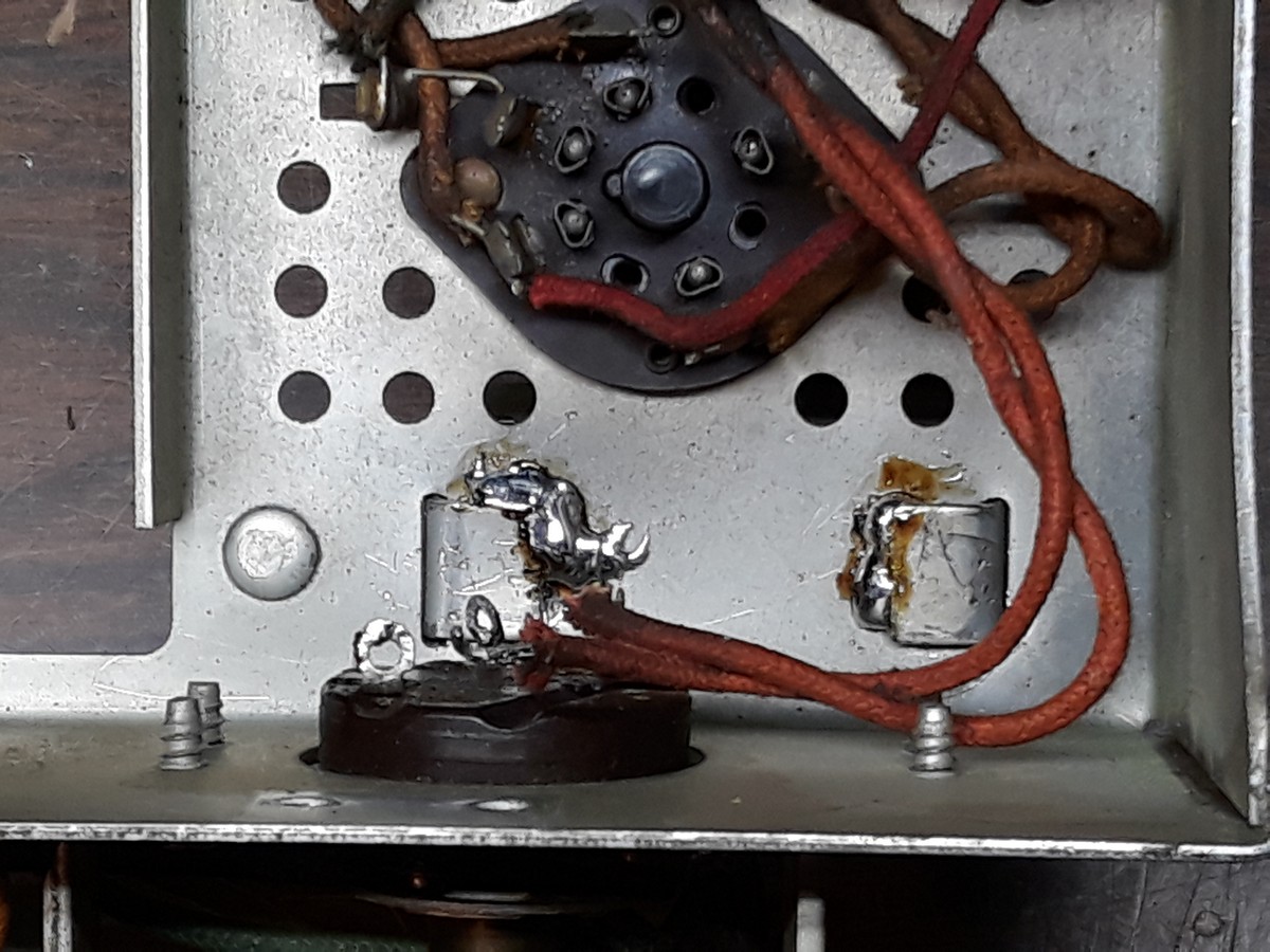
I managed to get the metal tabs folded back over again with help from a ha-ha-ha-hammer and a straight blade screwdriver. Of course, the tabs did not fold over as well as was done at the factory so the can was still loose on the chassis. This was cured by adding some solder to the metal tabs under the chassis.
--
Ron Ramirez
Ferdinand IN
Posts: 13,776
Threads: 580
Joined: Sep 2005
City: Ferdinand
State, Province, Country: Indiana
Next, I turned my attention to the Magic Brain.
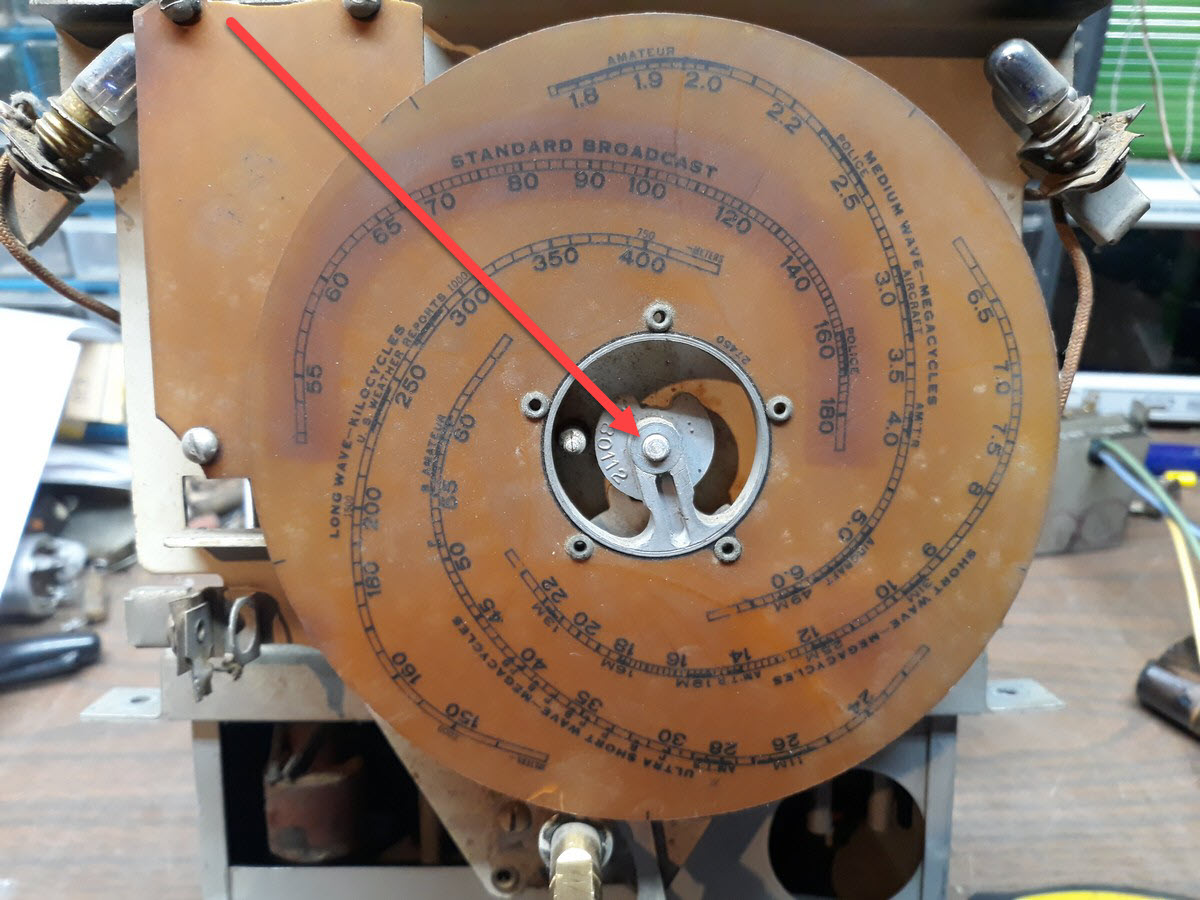
The first thing I did was to remove the main dial scale.
I pulled off the dial pointer (it wasn't easy to do).
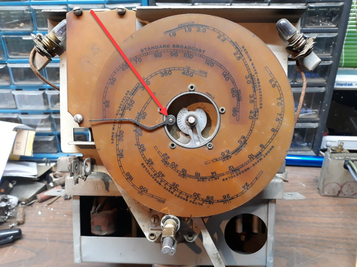
The dial scale assembly is held in place by a C-clip and a spring washer. Remove these, and the dial scale can be pulled off easily.
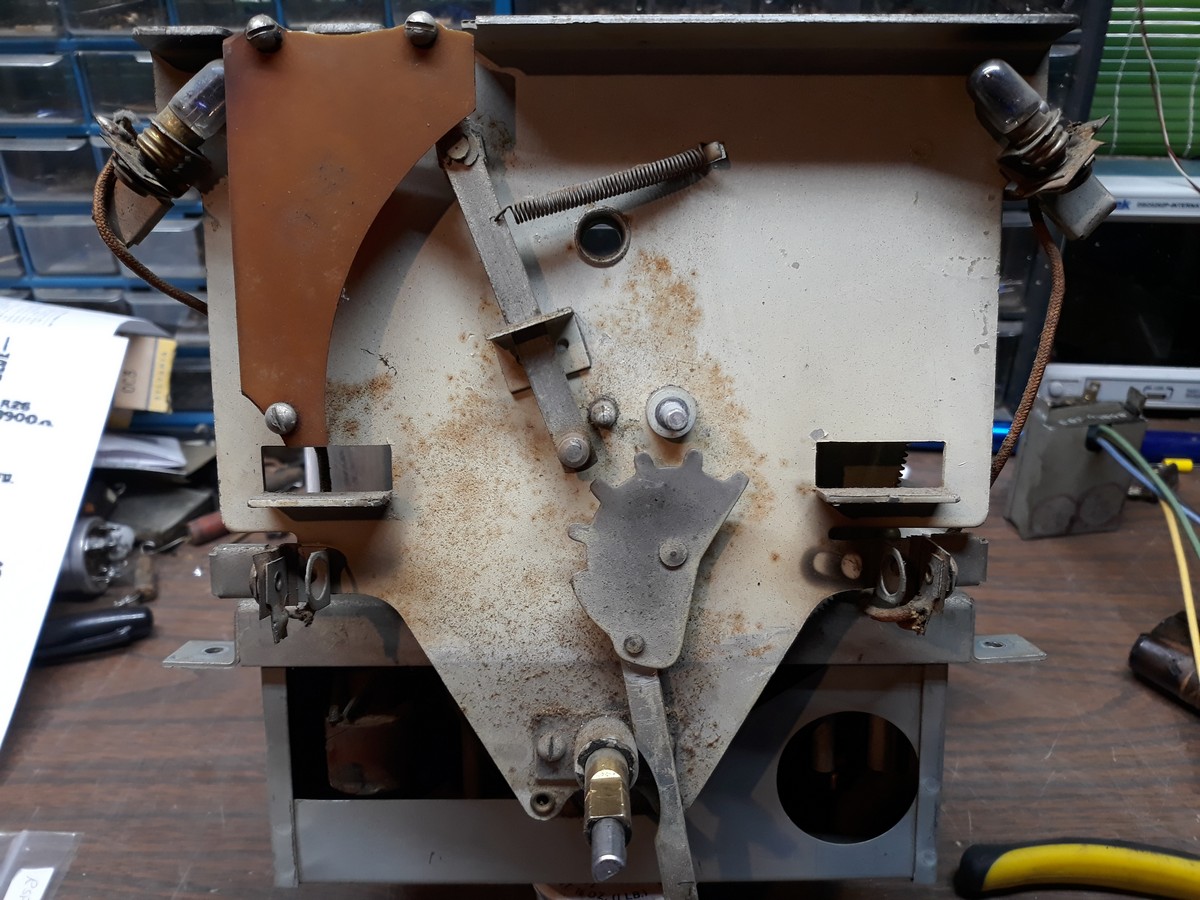
I found that the Magic Brain has more rubber-covered wiring than did the main chassis. Unfortunately, this also includes some of the wiring going from under the Magic Brain chassis to the octal plug which plugs into the main chassis.
Question for you people:
The ungrounded heater wire running from the octal plug to inside the Magic Brain chassis is shielded. Knowing that I am going to have to replace the wiring harness to the plug, is it really necessary for that heater wire to be shielded? There is less than 2 inches of cable sticking out from the Magic Brain unit to the octal plug. With the shielded metal tubes and all, I'm thinking it isn't really necessary for that heater lead to be shielded. What say you?
--
Ron Ramirez
Ferdinand IN
Users browsing this thread: 1 Guest(s)
|
|
Recent Posts
|
|
Need Help to ID this radio 11 tube Philco
|
| It is a 16B tombstone.morzh — 06:13 PM |
|
Zenith H725
|
| David - sorry, I reread your post and finally saw THD - now the % figures make sense. Thanks for explaining.
The PSU...EdHolland — 06:06 PM |
|
Need Help to ID this radio 11 tube Philco
|
| Hi Everyone,
New member but have been reading this for awhile for tips!
Vaccum tubes were before my time so bear with ...Ken D. — 06:03 PM |
|
My Philco 37-116 Restore
|
| Thank you MrFixR55, I appreciate your comments very much. I do not detect much hum if any so I will be staying with the ...dconant — 05:15 PM |
|
My Philco 37-116 Restore
|
| Hi DConant
Yes, you can replace chokes with resistors. You do stand the risk of increased hum. the solution is to inc...MrFixr55 — 04:23 PM |
|
Zenith H725
|
| 1.7-3.9 %, a modified Sine wave inverter is around 25%. Most generators from big box stores run 10% at a 50% load. What ...David — 04:06 PM |
|
My Philco 37-116 Restore
|
| I am having a heck of a time doing the alignment on the AM band. I can't seem to dial in the 1500 KC oscillator. I can h...dconant — 03:35 PM |
|
Zenith H725
|
| David - I think I understand but what units are you discussing (Low of 1.7, high of 3.9)?
Budget constraints for Ham ...EdHolland — 01:43 PM |
|
My Philco 37-116 Restore
|
| You're doing great.
I wish I could be more involved, but my mind is right now preoccupied with the reason I am here in ...morzh — 12:21 PM |
|
My Philco 37-116 Restore
|
| Hope you guys are still with me.
I have moved on to the alignment. I completed the IF alignment which was pretty muc...dconant — 10:47 AM |
|
Who's Online
|
There are currently 703 online users. [Complete List]
» 1 Member(s) | 702 Guest(s)
|
|
|

|
 
|


![[-] [-]](https://philcoradio.com/phorum/images/bootbb/collapse.png)


