Posts: 1,199
Threads: 49
Joined: Oct 2017
City: Allendale, MI
Posts: 1,199
Threads: 49
Joined: Oct 2017
City: Allendale, MI
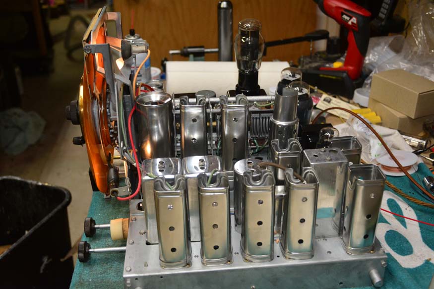
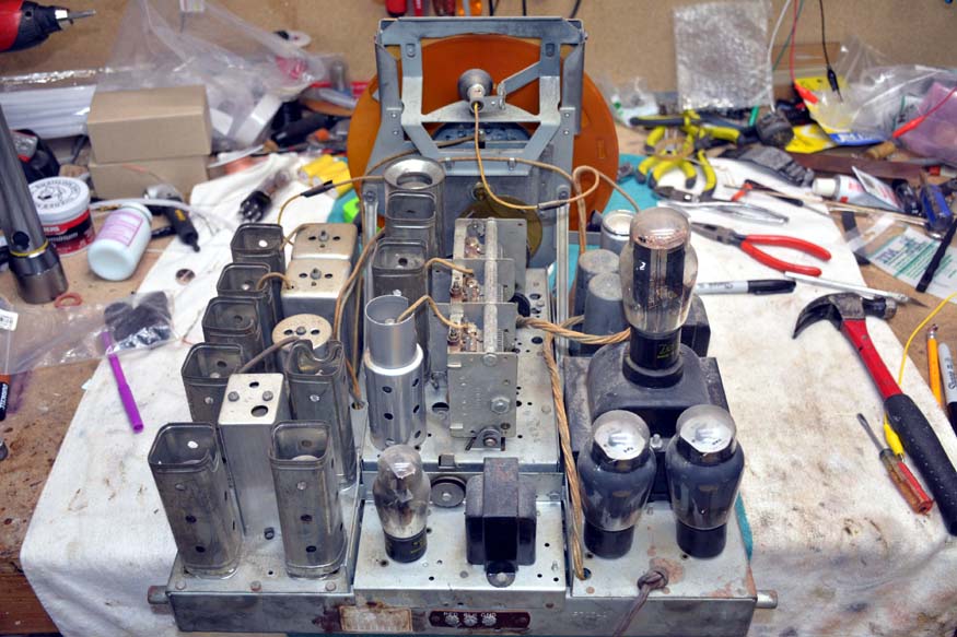
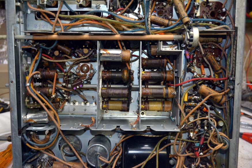
Gotta love modular construction. On the 37-116 the power supply section and the amp section came off as well, but these are riveted together.
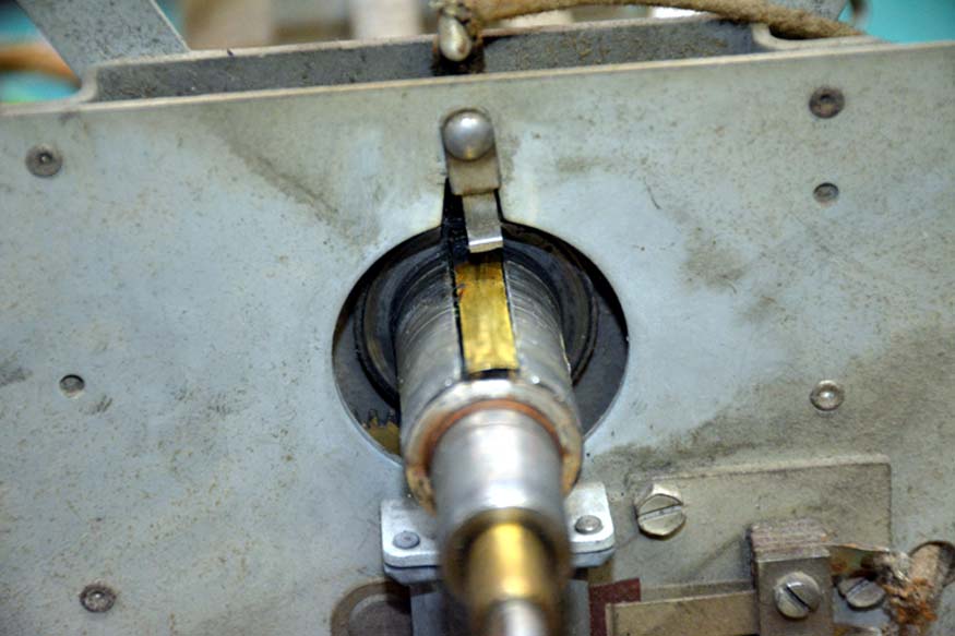
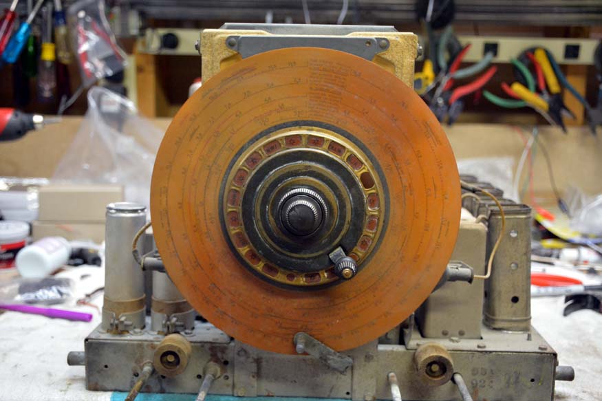
As I mentioned in another thread, there is a piece of the auto tune that is missing. The contact that kills the audio when the auto tune is engaged is missing. I guess I'll have to try and make one.

Posts: 1,199
Threads: 49
Joined: Oct 2017
City: Allendale, MI
Posts: 1,199
Threads: 49
Joined: Oct 2017
City: Allendale, MI
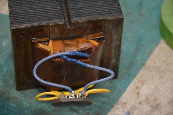
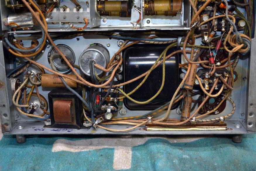
Crispy wires replaced. I've done it this way before. Is there a better way?

Posts: 1,475
Threads: 69
Joined: Nov 2012
City: Kansas city, MO.
Nice job on the rf sub chassis.
I've did the wires on the transformers the same way as you. Looks like too much risk to cut the paper and try and get to where they come off the coil.
Posts: 1,199
Threads: 49
Joined: Oct 2017
City: Allendale, MI
I agree that digging into the layers of paper would be messy and, perhaps, counter productive. The probability of damage could be high. That's why I've done it this way a couple of times. Hopefully it's good for another 50 years.
Posts: 1,199
Threads: 49
Joined: Oct 2017
City: Allendale, MI
The rectifier socket is wired for a 5X4. It would be easy to wire it to also take a 5U4, which is identical except for the pin out on one side of the filament and the plates. Has anyone done this? I have several 5U4's kicking around, but no extra 5X4's.
(This post was last modified: 01-04-2020, 08:09 PM by rfeenstra.)
Posts: 1,199
Threads: 49
Joined: Oct 2017
City: Allendale, MI
Oops! Never mind on the 5U4. Turns out the tube socket is missing the terminal for pin 4 - which would be one of the plate connections.
2 of the electrolytic cans were dry type. What a pain! it was very difficult to get the guts out. On one of them, the insides had expanded a bit and actually deformed the can ever so slightly. I wound up drilling as much of the guts out as necessary to get the much smaller Nichicons inside.
(This post was last modified: 01-04-2020, 08:54 PM by rfeenstra.)
Posts: 1,199
Threads: 49
Joined: Oct 2017
City: Allendale, MI
I have a volume control question for this radio. The "grounded" side of the volume control, according to the schematic, was left unconnected by the factory. There is no evidence of solder ever having been on the terminal. I wonder if the volume was ever able to be turned down to nothing. I'll leave it this way and test it. If it doesn't work properly on the bench, I'll add the ground connection. Have any of you run across this on your 38-116? My 37-116 is wired as per the schematic.

Posts: 1,199
Threads: 49
Joined: Oct 2017
City: Allendale, MI
After replacing 95+% of the wire, all of the capacitors and resistors, its first power up was a success! At 80 volts AC input, I had stations all across the BCB dial and all other bands as well (the highest band had very little activity but was working.) At full AC power, everything worked perfectly even without tube shields. Magnetic tuning is working as well as the selectivity control. I like it when things come together without problems!
The volume control works normally even without the ground side tied to ground so I'll leave it as it came from the factory.
Now to tackle the AutoTune assembly. I need to repair or replace both shadow masks. The dial is ok but I have a new one coming in case I break the original. It is very brittle. As I did with my 37-116, I may play with the AutoTune lighting of the station tabs. On my 37-116, it was very dim even though 4 lamps attempt to light it. The 38-116 has only 2. Plus, the polished reflector ring is broken and I don't know if I can repair it.


Posts: 1,199
Threads: 49
Joined: Oct 2017
City: Allendale, MI
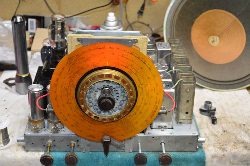
The radio has been playing all day. No problems as yet. I've finished most of the autotune system except for the audio killing switch. I'll need to "borrow" that from my 38-2. Next I'll do a realignment. The cabinet is ready to rub out for its final finish, then I can install the radio and be done. It seems to be an excellent performer. as is its older sibling, the 37-116.
Posts: 1,475
Threads: 69
Joined: Nov 2012
City: Kansas city, MO.
Great job well done.  I really like how neatly you did the wiring under the chassis.
Look forward to pics of it back in the cabinet.
Posts: 1,199
Threads: 49
Joined: Oct 2017
City: Allendale, MI
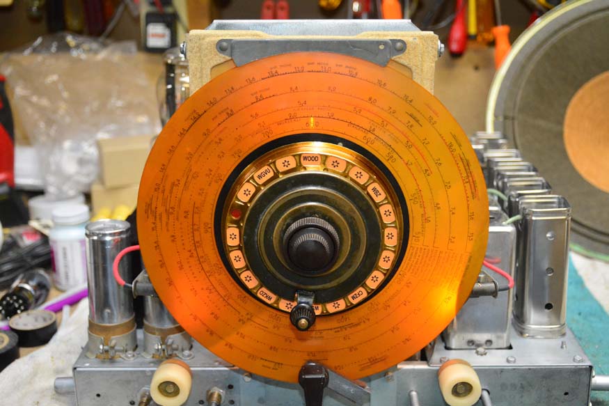
I think the chassis is about finished. I printed some new station tabs but need to work on the color a bit to make it match the dial. I'm working on the back lighting for the AutoTune dial. I have a PC board being made that will allow 16 LED's in a circle behind the dial. the LED's will shine through the dial and light the station identifier tabs in the Auto Tune dial instead of the reflecting ring that the designers used, which is ineffective. It will use power from the switched 6.3v lighting that turns on when the Magnetic Tuning is on (for Auto Tune use.) I hope it works out. I was not impressed with the lighting on the 37-116 and the 38-116 is even worse. I'll update when that is completed.
All tube shields have been tin plated and are shiny much like the original. It adds a nice touch.
While I wait for the lighting circuit boards to get here, I'll rub out the cabinet and get it ready for the chassis. The PC boards are coming from China so it will be a bit.
The radio has been working fantastic and I look forward to getting it in its cabinet.
I rebuilt the coupling between the tuning mechanism and the tuning capacitor using rubber washers from the local hardware store. It works but there is too much flexibility. There are no fibers in the washers so they stretch a bit when tuning. This causes very slight tuning problems when I tune back and forth to zero in a station. I have to find a 1/8" think belting material that has a fiber layer that allows flexing but not stretching.
(This post was last modified: 01-13-2020, 03:35 AM by rfeenstra.)
Posts: 16,484
Threads: 573
Joined: Oct 2011
City: Jackson
State, Province, Country: NJ
Looks sexy.
People who do not drink, do not smoke, do not eat red meat will one day feel really stupid lying there and dying from nothing.
Posts: 1,887
Threads: 214
Joined: May 2015
City: Seattle
State, Province, Country: WA
Wow - looks like new!
Awesome work.
Users browsing this thread: 1 Guest(s)
|
|
Recent Posts
|
|
Need Help to ID this radio 11 tube Philco
|
| If you want a radio that's difficult to work on, get a 37-620. The one side of the chassis is packed pretty tightly and ...Greg — 07:29 PM |
|
Need Help to ID this radio 11 tube Philco
|
| Philco 16 is not intimidating at all. Despite being an 11-tuber.
37-116 is indeed intimidating.
16 has good space unde...morzh — 04:11 PM |
|
48-482 rear panel help
|
| Thanks for the responses Gary and Bob. I'm a little surprised that there's no back panel - although I know older Philco'...keithchip — 04:09 PM |
|
48-482 rear panel help
|
| Gary is correct, there was not a rear panel on the 48-482. I restored one of those and its a great sounding radio that ...klondike98 — 03:24 PM |
|
The list of my radio & TV collection!
|
| A little light positivity in our feed... To nostalgic retro music...
With English subtitles
My new video on the contin...RadioSvit — 02:14 PM |
|
My Philco 37-116 Restore
|
| Ron and Mike I mentioned a 2 meg resistor not on the schematic. I stumbled on a changes note in Riders that mentioned th...dconant — 12:02 PM |
|
Need Help to ID this radio 11 tube Philco
|
| Here you go:
Your the code 125Radioroslyn — 11:12 AM |
|
My Philco 37-116 Restore
|
| Hi Ron,
Thanks for the input. I think I'm going to call it good enough. It does seem weird I can usually dial in othe...dconant — 08:01 AM |
|
Need Help to ID this radio 11 tube Philco
|
| Welcome,
the radio looks intimating 11 tubes, wish you well.Jimradio — 07:49 AM |
|
462ron
|
| Hi Dan, it’s been 10 years since I restored the electronics on my 37-116 so I’m going on some foggy memories. I remember...462ron — 07:37 AM |
|
Who's Online
|
There are currently 1111 online users. [Complete List]
» 1 Member(s) | 1110 Guest(s)
|
|
|

|
 
|


![[-] [-]](https://philcoradio.com/phorum/images/bootbb/collapse.png)


