Posts: 6
Threads: 2
Joined: May 2020
City: Deland
State, Province, Country: Florida
I need to know how to determine what size wire to use to create an output transformer to match a 3Q5 tube. Tube is 8K ohms plate resistance. Speaker is 3.2 ohms. Transformer is 440 ohms resistance. Speaker is 3.2 ohms. Also, how many feet of wire is needed? Cannot, thus far, locate this info on line. Help?

William Hardy. loneddie@cfl.rr.com.
Posts: 7,303
Threads: 269
Joined: Dec 2009
City: Roslyn Pa
You'll have to open the winding up and measure the diameter of the primary wire. Best guess it's going to be pretty small like 40-50ga. Once you know the size you can determine the length.
When my pals were reading comic books
I was down in the basement in my dad's
workshop. Perusing his Sam's Photofoacts
Vol 1-50 admiring the old set and trying to
figure out what all those squiggly meant.
Circa 1966
Now I think I've got!
Terry
(This post was last modified: 05-18-2020, 02:56 PM by
Radioroslyn.)
Posts: 16,533
Threads: 573
Joined: Oct 2011
City: Jackson
State, Province, Country: NJ
Or....if wanted, unwind the wire and count the turns.
Also....you are bent on rewinding, or could you aford to buy a universal Hammond?
People who do not drink, do not smoke, do not eat red meat will one day feel really stupid lying there and dying from nothing.
Posts: 6
Threads: 2
Joined: May 2020
City: Deland
State, Province, Country: Florida
can't count windings. radio did not have an output transformer. yes, I can afford to buy a Hammond. however, I am stubborn and desire to learn how to create and wire such. last hope, where do I buy the Hammond?

Posts: 6
Threads: 2
Joined: May 2020
City: Deland
State, Province, Country: Florida
that's my problem. I don't know how to calculate the length of the wire. At least, I think I know but need to rely on better guidance than my old noggin

Posts: 330
Threads: 30
Joined: Aug 2017
City: Hay Lakes, Alberta,Canada

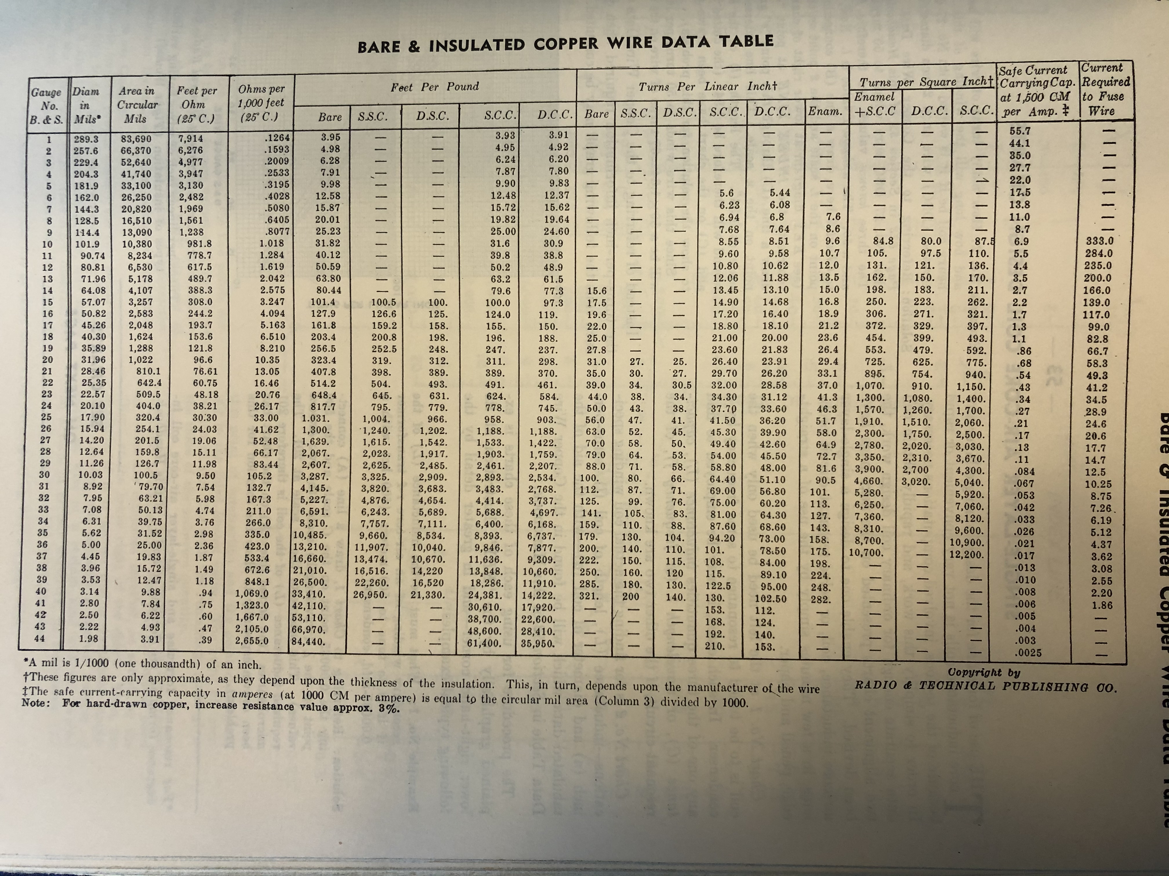
Here is a chart, from the Radio Troubleshooters Handbook:
Posts: 16,533
Threads: 573
Joined: Oct 2011
City: Jackson
State, Province, Country: NJ
Eddie
You need to know number of turns. And the gage.
And then what it takes, it takes, just have a spool big enough.
You DON'T go by resistance. You go by turns ratio.
And thatis dictated by the impedances, you turn ratio is square root of your impedances ratio.
Now, the number of turns of the primary is calculated either by formulae, or from tables that are in existance, given your minimum needed DC resistance and inductance, that determines your frequency response.
You probably could find a typical transformer design for your tyoe of output tube and the load.
People who do not drink, do not smoke, do not eat red meat will one day feel really stupid lying there and dying from nothing.
 William Hardy. loneddie@cfl.rr.com.


![[-] [-]](https://philcoradio.com/phorum/images/bootbb/collapse.png)


