Posts: 16,483
Threads: 573
Joined: Oct 2011
City: Jackson
State, Province, Country: NJ
Das war meine vermutung.
But it was working until I touched it.
I could explain the LDOs'mounted on the heatsink pins breaking solder: they were seriously displaced.
But the connectors should've not been affected by it, they are vertical and connected to wires, having experienced no displacement. Vibration? Again, the connectors are light. Shipping vibration is not enough.
Vibration due to CD transport vibration? Dunno.
My hope is, I fix it so it is enough for another 30 years at which point I won't be around and so won't really care 
But this thing is inconvenient to assemble.
The power board needs to be detached from the rear panel or else it won't go in. The rear panel cannot however fully detach as the power cord going through a cable clamp in it and then tacked to the board by another clamp held by plastic ribbed nails which is one time deal, to remove them I have to cut them. So the rear panel is hanging there interfering with maneuvering the board into the position and stressing the cord to board soldering spots.
A bear, a real bear.
People who do not drink, do not smoke, do not eat red meat will one day feel really stupid lying there and dying from nothing.
Posts: 1,199
Threads: 49
Joined: Oct 2017
City: Allendale, MI
Some things were not meant to be worked on!
Posts: 16,483
Threads: 573
Joined: Oct 2011
City: Jackson
State, Province, Country: NJ
Well...CD880 is also a very popular object for hi-end mods. Which includes full taking apart.
But when designing things, repairability should be kept in mind.
Having said this, do I always make things serviceable?
Well....I always try. But when the constraints defined by others are too....constraining, sometimes sacrifices are made. I don't like it, but.....
Well....it took me about 40 minutes to figure how to put the power supply in. Just because of those plastic ribbed nails.
People who do not drink, do not smoke, do not eat red meat will one day feel really stupid lying there and dying from nothing.
Posts: 16,483
Threads: 573
Joined: Oct 2011
City: Jackson
State, Province, Country: NJ
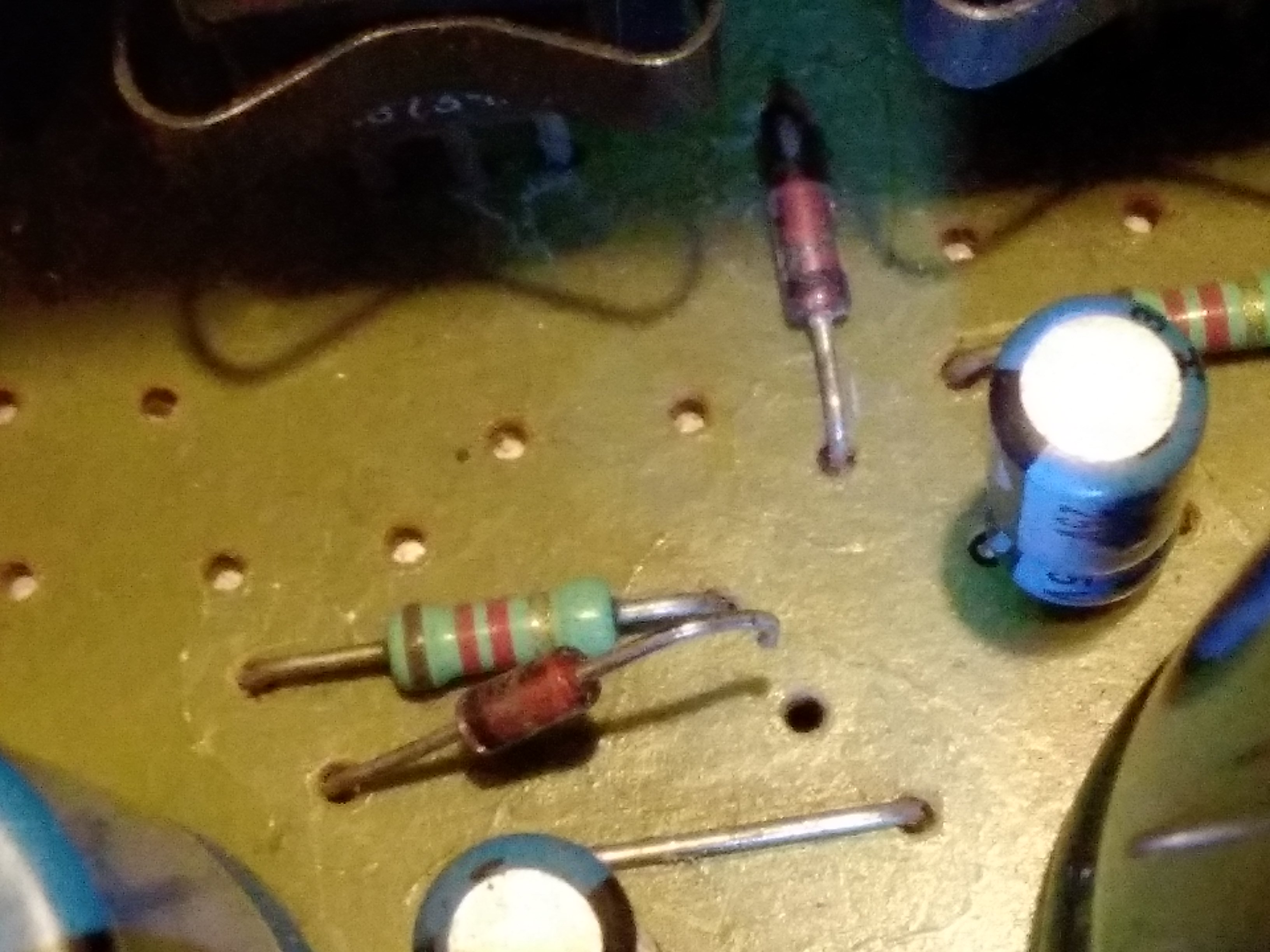
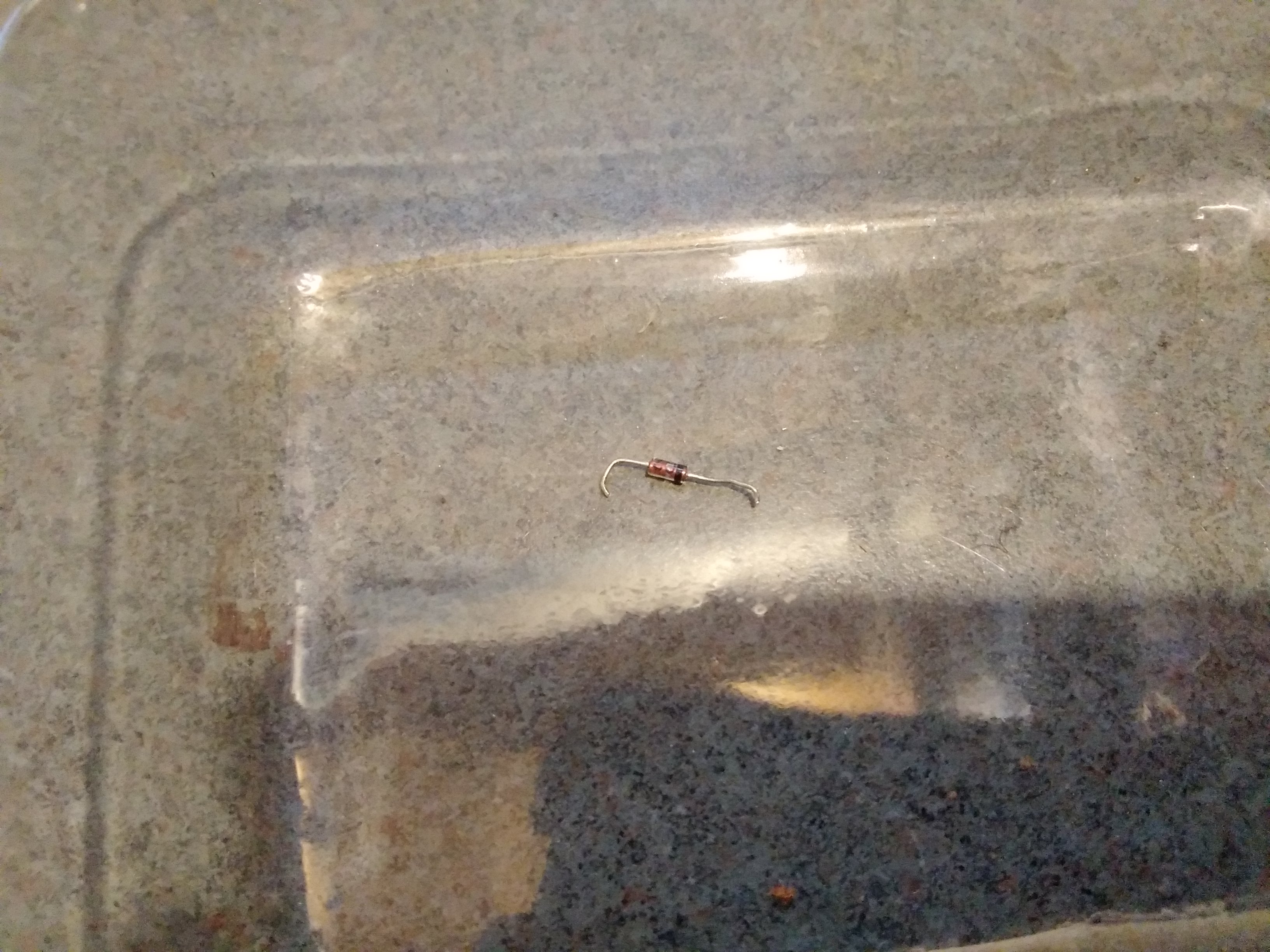
So....the Zener was connected after all.
It is simply shorted. So instead of 2.4V it drops 0V. Hence 8V instead of 10V.
I unsoldered one pin to make sure it is the Zener and not something else.
Now off to get the Zener.

People who do not drink, do not smoke, do not eat red meat will one day feel really stupid lying there and dying from nothing.
Posts: 16,483
Threads: 573
Joined: Oct 2011
City: Jackson
State, Province, Country: NJ
Just ordered Motorola 1N5221B from eBay. It is 2.4V 5% part.
PS. Never in my life saw I a shorted zener.
People who do not drink, do not smoke, do not eat red meat will one day feel really stupid lying there and dying from nothing.
Posts: 16,483
Threads: 573
Joined: Oct 2011
City: Jackson
State, Province, Country: NJ
So. The Zeners came yesterday (50 pcs for $1.50 plus $3.25 shipping). Today I installed it, check the 10.5V and it was exactly on the spot.
The CD worked with it being 8V, I guess it might be the VCC for some op amps and usually there is some margin plus common mode rejection for the power supply is anywhere from 90 to 120dB (didn't bother to check the datasheet...it works).
Anywho. I connected everything, and upon the button press the CD tray happily, easily, without any help rolled out.
I took it to the stereo setup, and it played just fine.
I need the remote to control the volume, the player came without it. I could buy a generic replacement for $13, or try to get the real one, which could, with shipping, easily get to a $100.
But so far I use the fixed output
What I thought was the volume control is indeed it, but for the phone output.
The potentiometer is bad. It is really scratchy, with some dezd zones....and there is no good way to deliver the Deoxit inside, the diameter of the bushing being small. Right now I don't care as I don't use phones. I will explore where to but a new one....willy-nilly, not a priority.
So, to recap:
1. The table roll-out fixed (the ew PRB belt), Lube and all also done.
2. The dent in the back and the consequences are removed.
3. The bad connections are fixed across the device (Power, Main Board, Phones board).
4. The incorrect +10V voltage (8V) fixed by replacing the bad Zener.

When I buy the remote, this thing will be complete.
People who do not drink, do not smoke, do not eat red meat will one day feel really stupid lying there and dying from nothing.
Posts: 16,483
Threads: 573
Joined: Oct 2011
City: Jackson
State, Province, Country: NJ
So. The Zeners came yesterday (50 pcs for $1.50 plus $3.25 shipping). Today I installed it, check the 10.5V and it was exactly on the spot.
The CD worked with it being 8V, I guess it might be the VCC for some op amps and usually there is some margin plus common mode rejection for the power supply is anywhere from 90 to 120dB (didn't bother to check the datasheet...it works).
Anywho. I connected everything, and upon the button press the CD tray happily, easily, without any help rolled out.
I took it to the stereo setup, and it played just fine.
I need the remote to control the volume, the player came without it. I could buy a generic replacement for $13, or try to get the real one, which could, with shipping, easily get to a $100.
But so far I use the fixed output
What I thought was the volume control is indeed it, but for the phone output.
The potentiometer is bad. It is really scratchy, with some dead zones....and there is no good way to deliver the Deoxit inside, the diameter of the bushing being small. Right now I don't care as I don't use phones. I will explore where to but a new one....willy-nilly, not a priority.
So, to recap:
1. The table roll-out fixed (the ew PRB belt), Lube and all also done.
2. The dent in the back and the consequences are removed.
3. The bad connections are fixed across the device (Power, Main Board, Phones board).
4. The incorrect +10V voltage (8V) fixed by replacing the bad Zener.

When I buy the remote, this thing will be complete.
People who do not drink, do not smoke, do not eat red meat will one day feel really stupid lying there and dying from nothing.
Users browsing this thread: 1 Guest(s)
|
|
Recent Posts
|
|
Need Help to ID this radio 11 tube Philco
|
| Yes the 16B as morzh pointed out. Specifically its the January 1935 model version of the 16B. There are a couple earli...klondike98 — 11:51 PM |
|
48-482 rear panel help
|
| Welcome to the Phorum, keithchip! How far you take a radio on cabinet restoration is a matter of personal preference. ...GarySP — 11:28 PM |
|
48-482 rear panel help
|
| I've recently finished the internal restoration of a locally purchased Philco 48-482. The cabinet is in ok shape except ...keithchip — 10:28 PM |
|
Need Help to ID this radio 11 tube Philco
|
| Welcome to the Phorum, Ken! Lots of help here for all of your restoration questions. Take care and BE HEALTHY! - Gar...GarySP — 07:59 PM |
|
Need Help to ID this radio 11 tube Philco
|
| Thank you.
I went to your online library and found 2 schematics.
I will download and compare to components!Ken D. — 06:31 PM |
|
Need Help to ID this radio 11 tube Philco
|
| It is a 16B tombstone.morzh — 06:13 PM |
|
Zenith H725
|
| David - sorry, I reread your post and finally saw THD - now the % figures make sense. Thanks for explaining.
The PSU...EdHolland — 06:06 PM |
|
Need Help to ID this radio 11 tube Philco
|
| Hi Everyone,
New member but have been reading this for awhile for tips!
Vaccum tubes were before my time so bear with ...Ken D. — 06:03 PM |
|
My Philco 37-116 Restore
|
| Thank you MrFixR55, I appreciate your comments very much. I do not detect much hum if any so I will be staying with the ...dconant — 05:15 PM |
|
My Philco 37-116 Restore
|
| Hi DConant
Yes, you can replace chokes with resistors. You do stand the risk of increased hum. the solution is to inc...MrFixr55 — 04:23 PM |
|
Who's Online
|
| There are currently no members online. |

|
 
|


![[-] [-]](https://philcoradio.com/phorum/images/bootbb/collapse.png)


