Welcome Guest! Be sure you know and follow the Phorum Rules before posting. Thank you and Enjoy! (January 12) x

Thread Closed
Thread Rating:
  • 0 Vote(s) - 0 Average
  • 1
  • 2
  • 3
  • 4
  • 5

Model 60B capacitors 2024 & 2025
#1

Ok,
   Here is my first post about my first restoration, you folks have answered a ton of foolish questions, SO... one more won't hurt.
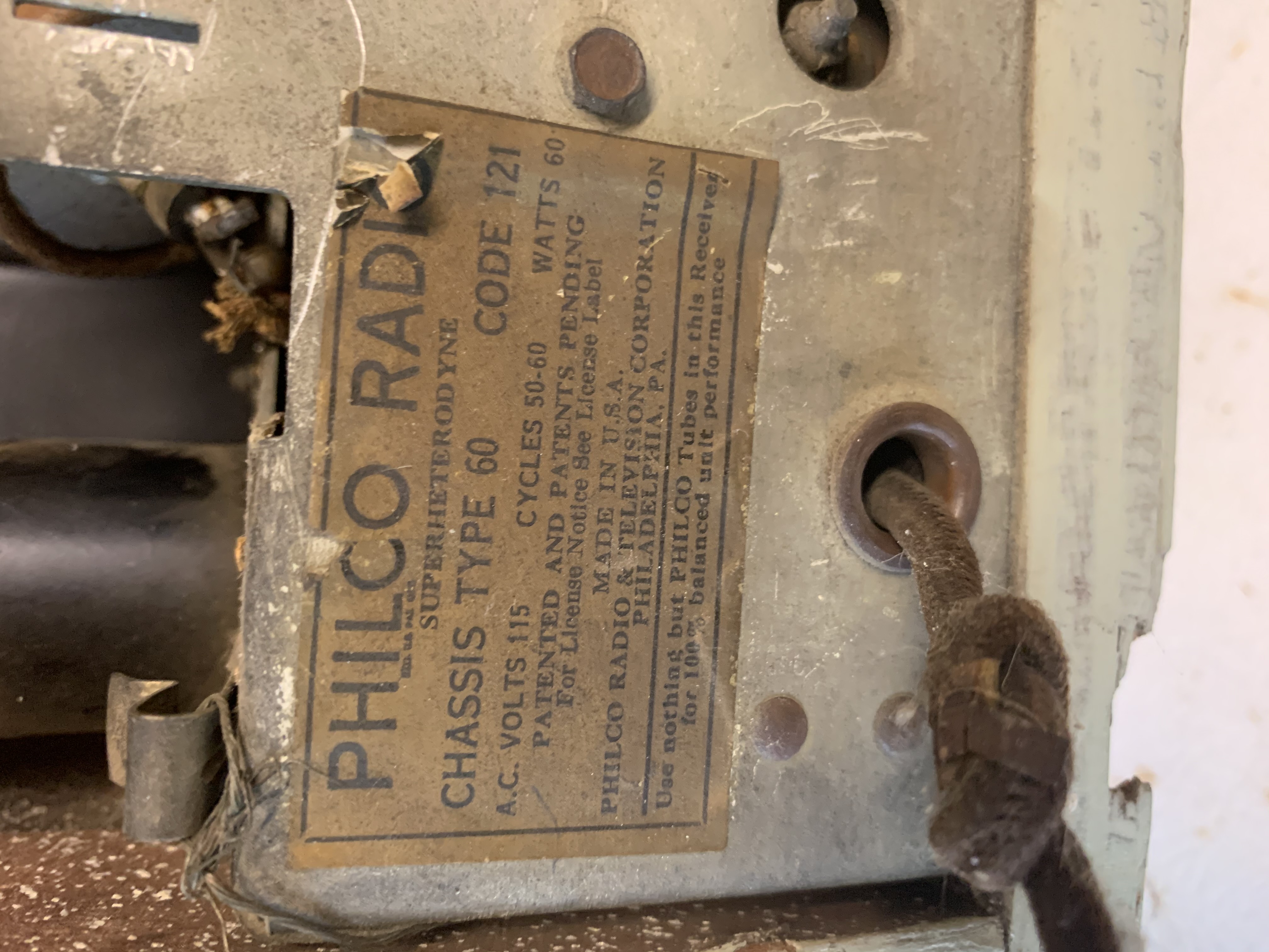
  I have bought a model 60B, 1934, if my research is correct, not bad for a $5 yard sale item.  I have researched some schematics and have a basic understanding of the components.
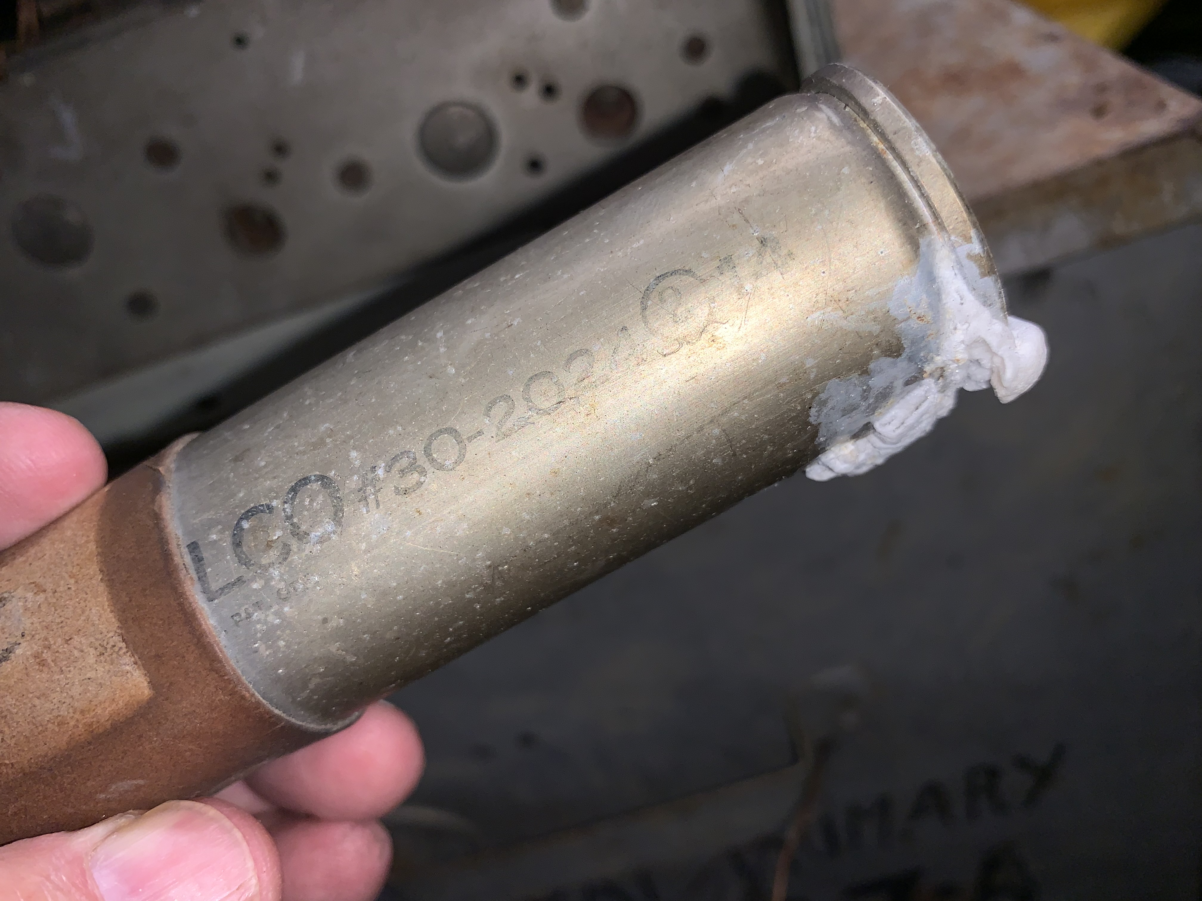
1) i have questions about the capacitors, from my research the 30-2024 is a 8 mfd, 450 volts, and the suggestion is to use a 10mfd, 450 volt as a replacement.

2) the second capacitor is a 30-2025, and the values i have found so far is has the same values as the 2024. Why the difference in part numbers? Also this 2025 cap had two wire soldered to the terminal in the center, where the 2024 only had one wired soldered the the center terminal.  

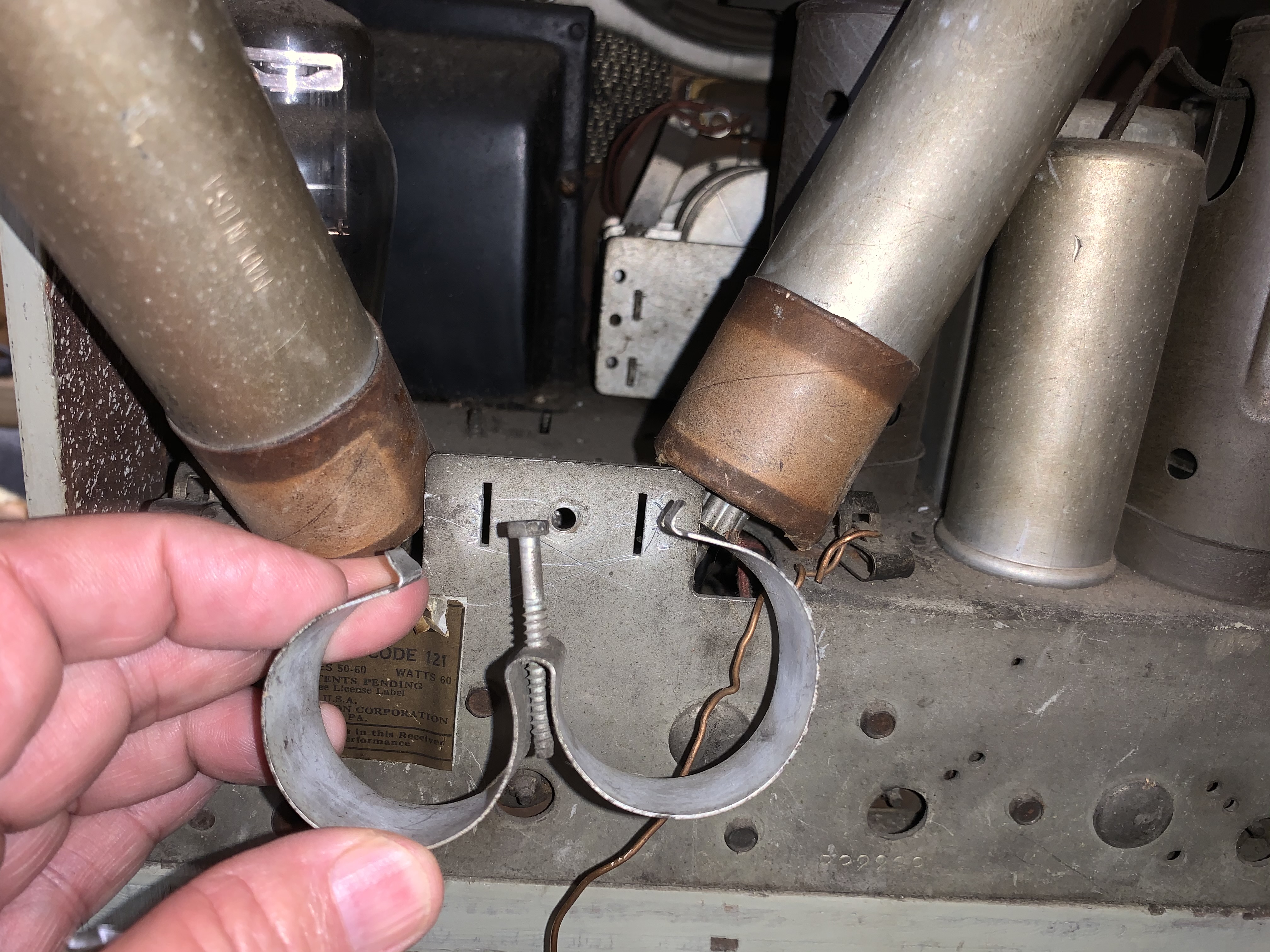
3) the capacitors had a cardboard sleeve around them, it looks like that would insulate them from the bracket that held the capacitors in place to the chassis. With only one terminal on each cap, both in the center, where would the ground or other wire be?

What do you think? Am i seeing the right?


#2

Hi and welcome,
>1) i have questions about the capacitors, from my research the 30-2024 is a 8 mfd, 450 volts, and the suggestion is to use a 10mfd, 450 volt as a replacement.
Yup your fine!

>Why the difference in part numbers?
Don't know and dead men tell no tales... You may look in any of the service updates and parts catalogs in the library. Philco make a billion model 60 sets.

>the capacitors had a cardboard sleeve around them, it looks like that would insulate them from the bracket that held the capacitors in place to the chassis. With only one terminal on each cap, both in the center
Yup you'll need them so don't muck them up unless you want to make new ones.

>where would the ground or other wire be?
Originally there was a metal tab that was fitted between the cardboard tube and the aluminum outer cover of the capacitor. If you look closely you may see an indent where the tab was fitted in the cardboard. The two tabs are connected together (the minus side of the filter cap) and connect back to the center tap of the power transformer. The metal outside of these two cap are NOT connected to the chassis as you mentioned.

GL

When my pals were reading comic books
I was down in the basement in my dad's
workshop. Perusing his Sam's Photofoacts
Vol 1-50 admiring the old set and trying to
figure out what all those squiggly meant.
Circa 1966
Now I think I've got!

Terry
#3

You might find this to be helpful: https://www.philcorepairbench.com/rebuil...trolytics/
If you get the page that has a little square that sez close just click on it and it will open the repairbench page.

When my pals were reading comic books
I was down in the basement in my dad's
workshop. Perusing his Sam's Photofoacts
Vol 1-50 admiring the old set and trying to
figure out what all those squiggly meant.
Circa 1966
Now I think I've got!

Terry
#4

Yes i think i will try to recan or restuff the Caps. I need to study the schematics a little more. I still want to see where the outside of the can connects. BUT its fun working on it so far
#5

There is a cap like yours that I stuffed in my 60MB. The pics might help you as well.
https://philcoradio.com/phorum/showthrea...5#pid85845


Users browsing this thread: 2 Guest(s)
[-]
Recent Posts
Need to purchase some accessories for restoration of my Old Philco Radio
Here is a list of resources found in our online library that you might find useful. Mike's Gobs of Knobs email addres...klondike98 — 01:46 PM
First Radio restoration
Hi Tubeman, Welcome to the Philco Phorum.  Phamily Phriendly Pfun with Phine Pholks Phull of Philco Phacts. (See a p...MrFixr55 — 12:33 PM
First Radio restoration
You could post in the WANTED ADs section here on the Phorum and see if anyone has an RF generator that they want to sell...klondike98 — 11:55 AM
Zenith H725
Good ideas, thank you Arrange and Rich. I have the adhesive aluminum foil already and can try that immediately. More ...EdHolland — 10:18 AM
Graphics for majestic 1050 dial glass.
Murf; I found this thread on the ARF, the first photo has a pretty good view of the dial glass. Regards ArranArran — 01:12 AM
Zenith H725
hello Ed, how about that speacial tape used for ducting it's like foil or how about thin piece of aluminum roof flash...radiorich — 12:19 AM
Zenith H725
Ed; One material that I have seen, but never tried for this was material for making exhaust gaskets, it's similar to ...Arran — 11:42 PM
Zenith H725
I just remembered, I have some hi temp silicone rubber material which could do the trick. Or a piece of FR4 laminate. Th...EdHolland — 08:39 PM
Zenith H725
The PSU filter cap arrived today (thank you USPS!) so I will work on that later. Meanwhile, I have the dial, speaker...EdHolland — 06:42 PM
Philco 610B oscillator wiring
Thanks Terry. After checking my notes I think I recorded about -10v at the 6A7 G4/control grid. The screen grid (G3 &...Tubester — 05:59 PM

[-]
Who's Online
There are currently no members online.

>