Thread Rating:
  • 0 Vote(s) - 0 Average
  • 1
  • 2
  • 3
  • 4
  • 5

Philco 39-7 restore help
#1

I am working on a Philco 39-7.  It is my third restore and first Philco.  I have verified the radio works and removed the chassis.  All voltages check out close to schematic.  My initial measurement and tests indicate the following items are need attention.

1. Largest issue is crumbling rubber coated wires needs to be replaced. (picture attached)
2. The power supply transformer wires are all rubber coated and crumbling very badly.  They will need to be replaced.
3. Volume/On/Off control is very scratchy and also the volume increases and decreases at random and when touched or moved.
4. Part #26 12 uf ecap was replaced under chassis with a 40 uf ecap. 
5. All transformers ohm out close to value on schematic.
6. Part #29 .006uF cap to be replaced with .01uf 250v Y2 cap.
7. Needs new polarized AC line cord.
8. Needs AC line fuse installed inside chassis.
9. Dial lamp needs to be replaced.
10. Replace all eCaps (2) and wax/paper caps (5).
11. Replace out of spec resistors (5).
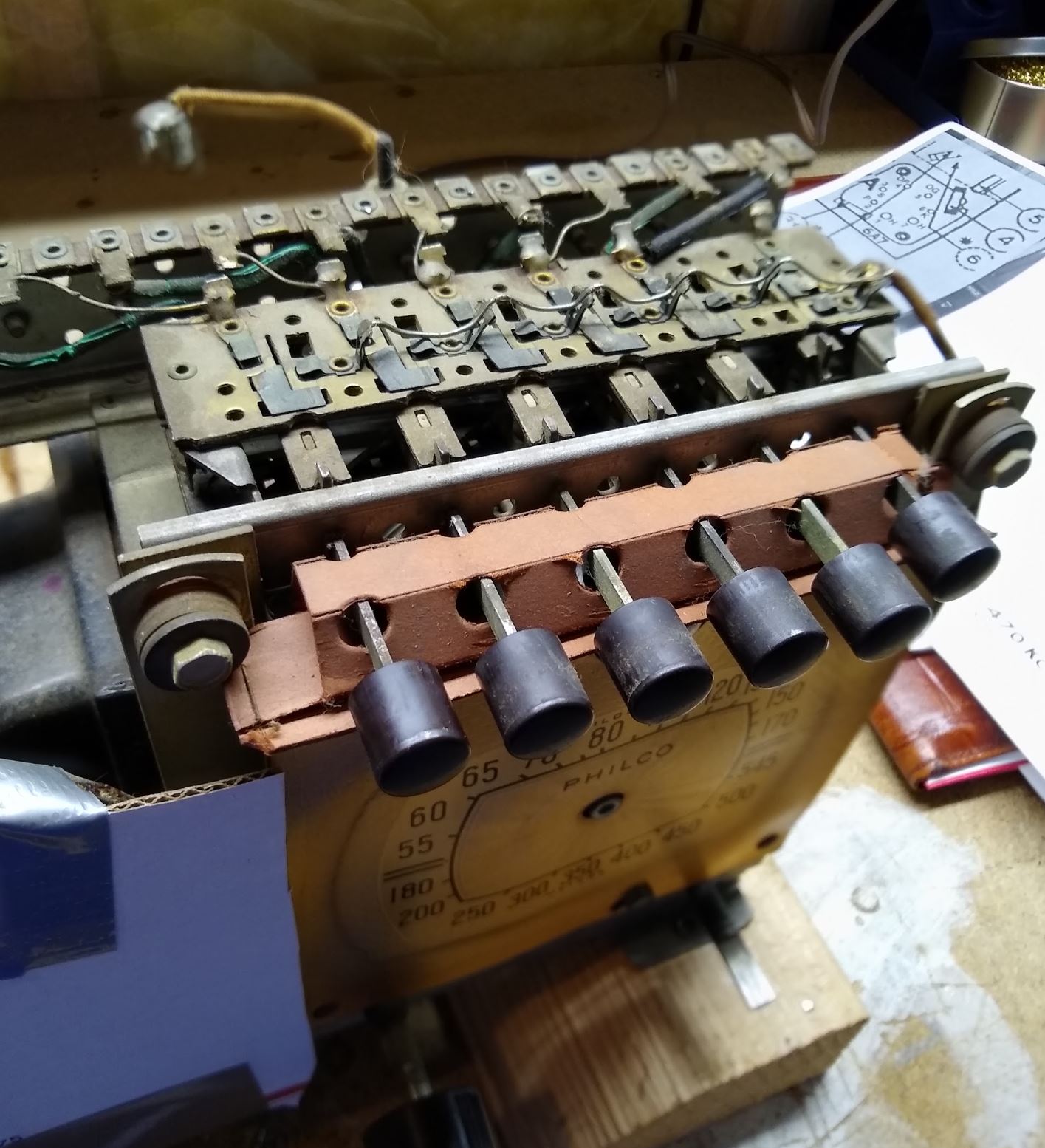
12. Button switching assembly seized and rubber wires crumbling. (picture attached)
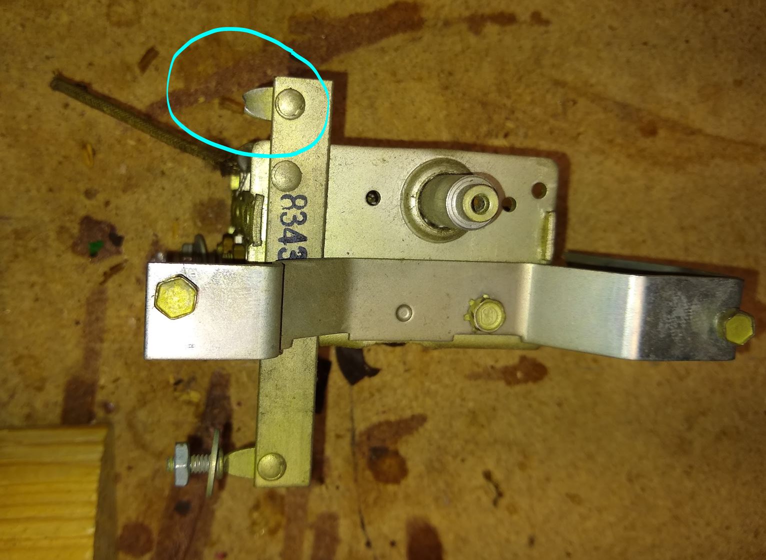
13. Tuning cap tower corrosion, crumbling rubber wires and broken mounting bolt. (picture attached)
14. Bending of dial face and rubbing of dial indicator.
15. Dial control restring needed.
16. Chassis and parts cleaning.
17. Cabinet refinishing.

At this early stage I a stripping down the chassis so that I can clean it and also work on some of the components parts.  I could use some option, comment or advise on dealing with the following items.

#1 What is a suitable wire replacement for this radio?  Gauge, stranded or solid conductor?

#2 What is the best way to replace the power transformer wires?  The rubber coating is cracked and crumbling all the way to the case and I suspect also inside the case.  I will know once I have removed it from the chassis.  I have never replaced wires on a transformer before.

#3 Can the Volume/Off/On control be opened and repaired or does a replacement need to be sourced?  Where can a replacement be found?

#4 Might there be a good reason that someone in the past replaced the 12uf ecap with on of such higher value (40uf)?  Maybe a factory suggestion or just what he had at the time.

#12 Is there a recommended reconditioning process for these button switch assemblies?  Is the point on the top of the IF can to secure the assembly grounded or insulated from the IF can?  Mine had parts of what looks like a rubber washer but i cannot tell if it was for vibration or insulation.

#13 I broke one of the tuning tower mounting studs when removing the nut on the underside of the chassis.  Picture attached.  What are some ideas of how to repair this effectively?

#14 Is there a recommended method to flatten and secure the dial face graphics to the plate they are attached too so that there is enough clearance for the dial pointer to mover in a complete arc without touching it?

Regards, John


#2

First of,

It was not a very good idea to verify the radio workrd without at least electrolytics replace ent.
But now that it went well, good to know.

The power cord can be anything that fits of desirable length. Matter of preference.
If want to be near-authentic, check Tubes and more, Radio Daze.

Transformer wires could be replaced, but many prefer simply sliding heatshrinkable tubing over. Works well.

Volume pot can be opened and lubed/cleaned.
If it fails, Mark Oppat has some or repairs those that could be.

40uF is not a recommended value and could even exceed the allowed one for the rectifier tube (see the datasheet, it always is listed there). It is possible because the other cap also dried up, they compensated this way.
Replace both with the proper values.


Fixing the stud: use an L-bracket and screws/a rivet and a screw.

People who do not drink, do not smoke, do not eat red meat will one day feel really stupid lying there and dying from nothing.
#3

Morzh. Thank you for the input and suggestions.
eCap before power up. Understood.

For my ongoing learning.

Is there proper/relatively safe method to bring the radio up on power without first replacing the eCaps?

In this case the past owner said he had turned it on a day before selling it to me and it worked but he could not tune stations. I checked the eCaps with a meter before hooking it up and they were close to spec and low ESR. I then used a variac and dim bulb tester to bring it up slowly to 115vac while watching for any indication of a short.

Is there something else I could/should have done?

I have a copy of the 84 tube datasheet that I used to identify the pins. I also looked up a second one but I do not see anywhere on these two datasheets a specification for the filtering capacitance. Could you point me to a datasheet that provides this information as it seems to be eluding me? Or is the a design chart or calculation needed to compute the value?

Regards, John
#4

Hi John and welcome to the Phorum,

#1 I like 22g stranded. I saw this https://www.tubesandmore.com/products/wi...-foot-roll but it seems a bit pricey if you are going to use several colors. I would shop around a bit and see what turns up. Radiodaze sold wire that was in smaller lengths and seemed to be a better price. They have stop selling a lot of electrical products in favor of graphics.
#2 Would use 18g (green) for the 6v heaters and black for the 120v primary. You want to be sure that insulation is rated high enough for the high voltage winding (abt 600v). Philco doesn't use the standard RMA code code for the wiring so it makes it a little confusing for us old timers. The hv winding is fine with 22g.
As for the replacement wiring pop the cover off and put the screws back in the core. Tighten them mark the wires as to which ones are which. Cut the wires reasonably short and use shrink tubing to insulate. Some transformers have a cardboard insert inside. This acts as an insulator also. If it doesn't have one I would consider adding a little something. RMA code would be black for the primary,green for the 6.3v heater, red for the high voltage winding, red/yellow for the center tap.
#3 https://www.tubesandmore.com/products/po...pst-switch Pick 500K. Will have to cut and file a flat on shaft.
#4 I don't think 12mf is a standard value anymore. 20mf at 450v is fine get two. 40 is a bit excessive.
#12 I've used Qtips and a bit of mek (lacquer thinner) to clean the contacts. The washer is there to prevent microphonics (vibration).
#13 Remove rivet by drilling or grinding. Fashion a suitable bracket and use screws to mount it.
#14 With the pointer removed fasten a thin piece of clear plastic over the dial using the two mounting screw. This can be form an used blister pack something from the bakery perhaps. Put a hole in the center for pointer.

Back in the 80's I had the chairside version the 39-7CS. Same as your set but used an 8" spkr. Great player.
GL with your new project!

When my pals were reading comic books
I was down in the basement in my dad's
workshop. Perusing his Sam's Photofoacts
Vol 1-50 admiring the old set and trying to
figure out what all those squiggly meant.
Circa 1966
Now I think I've got!

Terry
#5

https://www.radiomuseum.org/tubes/tube_84.html

This is the datasheet in a nutshell.
The 40uF value is max cap.
Also it raises the B+ voltage.
As Terry said, 12uF is not standard today.
I use 2x22uF 450V in series, that yields 11uF. 20uF is ok too.

As for bringing up radios without recap, the only reason for it is to validate the power transformer.
You could do it by pulling the rectifier tube (and you might choose to pull the rest but not necessary)
and then measuring the high V AC at where the plates of it go in the tube panel, and heaters low Vs.
I see no reason to power fully populated radio otherwise before recap.

People who do not drink, do not smoke, do not eat red meat will one day feel really stupid lying there and dying from nothing.
#6

The electrical work is proceeding.

I have attached new wires to replace the crumbling wires on the power transformer.  I used shrink wrap and then some liquid electrical tape to cover the exposed part of the connection where I could not get the shrink wrap.  Here are before and after pictures.


I have started to replace the wires in the chassis with crumbling insulation one by one.  I decided to strip down the chassis as most of the wires going to the IF transformer will need to be replaced and I thought it would make rewiring easier if everything was removed.  It will take some time and I will change out the caps and resistors as I change the wiring.  I have taken many pictures and lots of notes to ensure I place wires back with the same routing.


I have used Dexoit to clean up the contacts on the top and bottom of the button selector assembly.  It now works smoothly and looks much better.  I am not sure if I want to tackle replacing the green wires that look to be crumbling or leave well enough alone.  They are fairly short and there is not any movement on them when the buttons are operated so I do not think they would be much of a shorting potential even if all the insulation dropped off.


One of the tube grid caps came off when I was trying to remove the cap connector.  It was stuck on.  I looked up how to repair it using epoxy or super glue.  I will give that a try as I think there is a good chance for the repair to work.

I was trying to source replacement grid cap connectors and I cannot find any that look the same as the originals.  I only found the ceramic type.  
Does anyone know a source for these? 
I will need to replace the wires and might as well replace the cap connectors.  
The wire seem to be cloth covered and one has a metal spring type sleeve.  
Do these wires need to be special or can I use regular 20 ga hookup stranded 600v hook up wire as a replacement?


I used some Evaporust to clean the top of the chassis.  It removed the surface rust but left a very uneven pattern.

Should I consider painting the top of the chassis with Krylon Silver or does that present some issues later?

Regards, John
#7

Yes you can use AWG20 regular wire.
The "spring type sleeve" is the EMI shield, si make sure it is Grounded same way it was befire.

People who do not drink, do not smoke, do not eat red meat will one day feel really stupid lying there and dying from nothing.
#8

You might have removed the plating in those areas - don't feel bad, the rust beat you to it. If I had a chassis that was stripped down that far (I do), I would have it replated. It isn't like chrome. It does not need to be shiny smooth, Just clean, The same clean as you would need to solder two pieces of metal together.  Take it to a plater or do it yourself (I am).

In fact, I just pulled a 5-tube Zenith chassis out of the copper bath. It is still a little pitted but most of that will be covered by components and it will turn orange in a while, it is kinda' pink now. I'll be posting some pictures and stuff, but that is still a few weeks away.

No, I would not paint a plated chassis. BTW, you can get the rivets from Mouser. You probably already have a hammer. Icon_lol

Russ

"I just might turn into smoke, but I feel fine"
http://www.russoldradios.com/
#9

Russ

I did a bit of research on self plating and it seems although a good method the startup costs are fairly high. I found that even a kit could be purchased from Caswell for $250 + depending upon container size. That does not include the power supply needed to control the reaction. I don't expect to be restoring more than 4 - 6 chassis per year as a hobby.

Is there a more economical bare bones method to start plating?
With the long time between projects can the plating materials be used over several project for a year or more?
If they can be used over what space and issues are expected with the storage of the materials?

If I can get started plating for an initial investment of $50 to $75 and the materials can be safely stored between projects without being conspicuous, I would be willing to give it a try. Provided the bare bones plating will result in a finished product that looks professional. Having never done it before it my not be feasible but I thought I would ask someone more knowledgeable before dismissing it and deciding to use paint on the chassis.

John
#10

I replaced all the crumbling rubber wire with new.  I decided to also replace the four wires inside the IF can just to be sure.  Working carefully it was successful however I did notice that the very small diameter transformer magnet wire that connects to each solder tab appears to have a covering that has deteriorated and allows the individual wires to seperate.  Electrically the connection to the tab is good and secure but I am wondering if I should take some preventative action or just leave well enough alone.  With these small wires the risk to do some permanent damage is high so I though I would ask for some advice here.

Thanks, John


#11

Would leave them alone. It's not a simple task to rewind if broken. Looks like it maybe wound with litz wire. This is stranded wire made up of very small gauge strands. It's typical failure is rot as it's not used in situations where there is movement.

Look's Good so far!

GL

When my pals were reading comic books
I was down in the basement in my dad's
workshop. Perusing his Sam's Photofoacts
Vol 1-50 admiring the old set and trying to
figure out what all those squiggly meant.
Circa 1966
Now I think I've got!

Terry
#12

All the rewiring and out of spec components replaced.  Need to do a double check.  Decided to paint the chassis and have remounted most of the components except the push button selection assembly.  I am currently replacing the bad rubber coated wire within that assembly.  Still debating if I can save the finish on the cabinet or if I just just go ahead and strip it and refinish.  One question I have is if the dial bezel was shiny brass when new or just a brass/gold colored paint?

John


#13

Chassis is looking good! Pretty sure that the bezel should be polished and that's not plated but solid brass. Same w/the station tab holder. There is a small brown insert between the glass and brass. I would go ahead and refinish. It's a small cabinet with out any masking so the job is rather simply.

When my pals were reading comic books
I was down in the basement in my dad's
workshop. Perusing his Sam's Photofoacts
Vol 1-50 admiring the old set and trying to
figure out what all those squiggly meant.
Circa 1966
Now I think I've got!

Terry
#14

I polished the bezel on my 37-9 chair side.  I didn't like it so I sprayed brown toner on it - light coats until I got the effect I wanted.  that gave it a bit of an antique look.  I like it.

   
#15

Ok I need some expert help.  Chassis completely reassembled and when testing there were no broadcast stations heard.  Did some troubleshooting and I could not hear the Oscillator on a second receiver.  I checked continuity and found that point 3 of the oscillator transformer was not connected.  I got continuity between point 5 and 4 but nothing between 5 and 3 and 4 and 3.  I removed the Osc transformer from the chassis and examined it with a magnifier.  Inside I could see that the small transformer wire had broken away from the terminal connection inside.  I pulled it thru to the outside in the attached pictures so that I could test that it was only the connection point and not a open circuit within the winding.  I was able to confirm it was only the connection point.

That being the case I either need to replace this Osc transformer if that is possible or make a repair.  If making a repair what is the recommended process?

Soldering connections back to these terminal is somewhat problematic as the heating of the terminals transfers heat quickly to the transformer wire and that might  have been why I now have a open connection.

Any guidance, suggestions or help with a repair or replacement would be appreciated.

Regards, John


Users browsing this thread: 1 Guest(s)
[-]
Recent Posts
American Bosch Model 802 auto radio
Hello again;   I found a model 838 car radio on Nostalgia Air under United American Bosch, http://www.nostalgiaair.org/...Arran — 09:32 PM
New Philco Repair Bench
Morzh is correct. The repair bench on our website is an archived image of chuck’s original site. He no longer provides s...klondike98 — 05:32 PM
Made mistake & did not label connection
Excellent information. It is all starting to come together now and your explanation really helped since I noticed that ...georgetownjohn — 04:39 PM
Made mistake & did not label connection
Hi John, I don't have this radio, but I can supply some info: Based on your pic, pins 7,8 and 1 are used together, go...MrFixr55 — 02:02 PM
New Philco Repair Bench
As far as I know, the Repairbench does not work, and has not been working in a while. Chuck (we had that campaign looki...morzh — 01:33 PM
Radio city products 664 schematic request
Need a schematic or manual for the 664. The 663 may be similar.daveone23 — 12:38 PM
New Philco Repair Bench
Thanks Gary.dconant — 12:16 PM
New Philco Repair Bench
I tried accessing the site through our library and got the same response. It's reported to our tech gurus. GaryGarySP — 11:50 AM
New Philco Repair Bench
I am sure this is the archive, and not the Chuck's site.morzh — 09:50 PM
Made mistake & did not label connection
It's not like we are good friends with that wire and can tell it from other ptetty identical looking wires. Why'n't you...morzh — 09:49 PM

[-]
Who's Online
There are currently no members online.

>