Posts: 124
Threads: 24
Joined: Oct 2016
City: Whitehall PA
After a diversion restoring a 6-D-539 chassis I'm back to the 37-116.
Since I'm re-stuffing the capacitors it seemed like a sin not to "re-sutff" the bad, flexible 400 ohm, 1/2W resistor in the RF chassis. The original's resistance read quite high and varied as I "wiggled" it.
The insulation was gotten from some Radio Daze some cloth covered. It has PVC(?) insulation inside and the insulated wire pulls out easily. The resistor inside is 4x 100 ohm, 1%, 1/4W resistors. I drilled small holes in the end caps to pass the new resistor leads out to the original, external leads. I think the end caps are aluminum and didn't trust soldering to them. I added a couple bands with markers and that was that. However I wouldn't want to flex it much. The 1/4W resistor wires are pretty fragile.
Considering nobody will ever see this buried in the RF chassis I'm starting to think I'm nuts...
It looks like the original hair thin, nichrome(?) wire was passed through the end of the caps and crimped with the external leads.
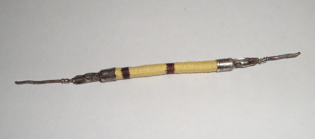
Can't think of anything witty.
Greg O.
Whitehall, PA
Posts: 869
Threads: 50
Joined: Feb 2013
City: Shenandoah,
State, Province, Country: Pennsylvania
Hi Greg, folllwing your restoration of your 37-116 as I have one myself. I’ve always wondered if there is something special about those flex resistors that Philco used? Is there any reason why you can’t replace them with a regular resistor?
Ron
Bendix 0626. RCA 8BX5. RCA T64
Philco 41-250. Philco49-500
GE 201. Philco 39-25
Motorola 61X13. Philco 46-42 Crosley 52TQ
Philco 37-116. Philco 70
AK 35 Philco 46-350
Philco 620B. Zenith Transoceanic B-600
Philco 60B. Majestic 50
Philco 52-944. AK 84
Posts: 16,495
Threads: 573
Joined: Oct 2011
City: Jackson
State, Province, Country: NJ
There is no reason.
It seems it was popular for low values to be wire-wound.
People who do not drink, do not smoke, do not eat red meat will one day feel really stupid lying there and dying from nothing.
Posts: 869
Threads: 50
Joined: Feb 2013
City: Shenandoah,
State, Province, Country: Pennsylvania
Gotchya, thanks Mike!
Ron
Bendix 0626. RCA 8BX5. RCA T64
Philco 41-250. Philco49-500
GE 201. Philco 39-25
Motorola 61X13. Philco 46-42 Crosley 52TQ
Philco 37-116. Philco 70
AK 35 Philco 46-350
Philco 620B. Zenith Transoceanic B-600
Philco 60B. Majestic 50
Philco 52-944. AK 84
Posts: 7,300
Threads: 268
Joined: Dec 2009
City: Roslyn Pa
I can only think of two reason. Fitment in that maybe in too close quarters for a 1/2 bed resistor. The other is there maybe a slight inductive quality of the wire wound resistor.
When my pals were reading comic books
I was down in the basement in my dad's
workshop. Perusing his Sam's Photofoacts
Vol 1-50 admiring the old set and trying to
figure out what all those squiggly meant.
Circa 1966
Now I think I've got!
Terry
(This post was last modified: 05-15-2020, 09:38 AM by Radioroslyn.)
Posts: 16,495
Threads: 573
Joined: Oct 2011
City: Jackson
State, Province, Country: NJ
Terry,
For a wirewound resistors the parasitic inductance is considered to be...well...parasitic, right?
So much so todays WWR are done in bifilar way so to eliminate it.
So other than stability of a wirewound, I don't know what other reasons they would have.
But as the stability goes, the rest of the resistors were carbon, so to have some resistors stable and some not.....
The cathode resistor is DC bias / Negafive feedback, so stability might be a consuderation but then there are other circuits with higher value dividers that could benefit from stability, but used carbon resistors nevertheless.
Maybe it is simply because it was easier to make the low value ones from a wire and higher from carbon? Just technological, no circuit theory behind it?
People who do not drink, do not smoke, do not eat red meat will one day feel really stupid lying there and dying from nothing.
Posts: 124
Threads: 24
Joined: Oct 2016
City: Whitehall PA
Finally some more progress...
The coils in the RF chassis, with the exception of the one I fixed, checked out OK. All of the capacitors in it have been re-stuffed and a few bad resistors replaced new ones made to match the originals.

The RF chassis is back together, except the tuning capacitor. I need to get a grommet for the back end of it first.
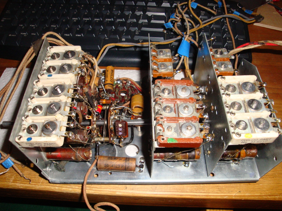
I plan to finish the main chassis then for initial testing I'll clip-lead in the RF chassis. I don't want to have to remove it if anythings wrong. I know, how could that possibly be  .
I'm working on the Bakelite block capacitors. The first one went fine. The next was the line filter block. It wasn't so fine. It had a catastrophic failure at some point. One side and the back were blown out. I found the side, but not the back. I glued the side in place, created a new back and corner with epoxy putty, spray lacquered it black and re-stuffed it.
Before:

During/After...
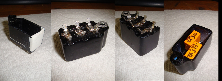
Onward and upward...
Can't think of anything witty.
Greg O.
Whitehall, PA
Posts: 124
Threads: 24
Joined: Oct 2016
City: Whitehall PA
Well I discovered the primary of the Input Audio Transformer is open. That's not good. I'll probably take it apart to see if the break is visible. I can't make it that much worse.
I think my yet to be restored 116b has the same transformer. I might "borrow" that one until I decide what to do.
Any suggestions?
Can't think of anything witty.
Greg O.
Whitehall, PA
Posts: 2,118
Threads: 112
Joined: Jun 2010
City: Medford OR (OR what?)
If it is inside of the metal "bell" then just throw in a new one. There is a guy that sells interstage trans w/o the core up to about 1".
https://www.arbeiii.com/Transformers/
This is the same guy that builds/sells the ARBII. $33
"I just might turn into smoke, but I feel fine"
http://www.russoldradios.com/
Posts: 124
Threads: 24
Joined: Oct 2016
City: Whitehall PA
I looked at the battery eliminator guy's transformers. The core-less ones are too small. I need 1"x1" and his are 3/4". I suppose it's possible I could fit an entire transformer into the old housing.
Next I let myself get talked into rebuilding the original. I ordered wire and did some calculations based on the bobbin size, wire gauges, primary resistance ... It's a lot of wire, but not impossible. So I ordered the wire.
The transformer wire wire arrived. The following day something motivated me to look on Ebay for a replacement (didn't find one earlier). There can't be too many of them out there. Sure enough I found one. So I bought it. Looked new.
I got it today and it sure looks new. However the primary resistance sure doesn't read like new. It's better than the original (primary open) but reads ~5.5K ohms instead of the specified 420 ohms. That can't be good.
Is there some failure mode on these that affects the primary? The only thing I can think of is the wire corrodes at some point and it goes open or the resistance increases as in the case of the second one.
Better start thinking about winding...
Can't think of anything witty.
Greg O.
Whitehall, PA
Posts: 124
Threads: 24
Joined: Oct 2016
City: Whitehall PA
Question...
What are the three leads from the three section capacitor, part #89 connected to inside the can? It's a 30-4466 (no catalog entry) with 0.1, 0.1 and 0.8 uF capacitors. It's in rectangular tin can above the chassis with two tabs holding it in place.
Maybe I need to be "more smarter", but I don't understand how it can only have three leads when two of them connect to the same point, part 85. That would suggest the two 0.1uFs are grounded by internal connection to the can and the can is connect to the chassis by the two tabs that lock it in place. That seems like a lame way to ground something.
My guess is, and my dog agrees with me, that the leads would be:
1 - Common with one side of "upper" 0.1 and one side of the 0.8 connected to it. This connects to #88.
2 - Other side of 0.8 connected to #85.
3 - Lower 0.1 connected to #85.
Can - Both 0.1's connected to it and it connected to the chassis via the two tabs.
I suppose I'll find out when I take it apart.

Can't think of anything witty.
Greg O.
Whitehall, PA
Posts: 1,889
Threads: 214
Joined: May 2015
City: Seattle
State, Province, Country: WA
Hi Greg,
I recently worked on a 37-116 (Standard) and puzzled over that same can too.
Here is what I figured out based on peeling apart the original sections and comparing against the schematic.
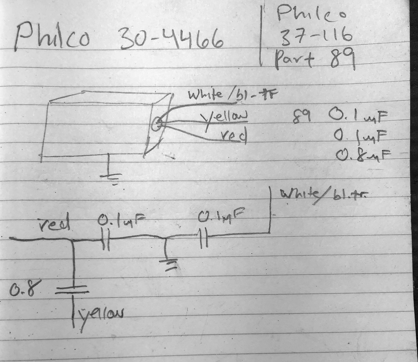
I think that matches your dog's intuition.
Posts: 124
Threads: 24
Joined: Oct 2016
City: Whitehall PA
Thanks Nathan.
Can't think of anything witty.
Greg O.
Whitehall, PA
Posts: 1,199
Threads: 49
Joined: Oct 2017
City: Allendale, MI
The schematic shows a detail of that cap assembly. It is curious as 2 leads are connected to the same terminal. I would suspect that that is a part that is left over from a previous design. But if you follow the schematic and the detail of the capacitor, you will come out good. I recently completed 2 37-116's and looked closely at the connections to the leads from that can. I have pics of the connections. It does work out per the schematic, and does work in the real world.
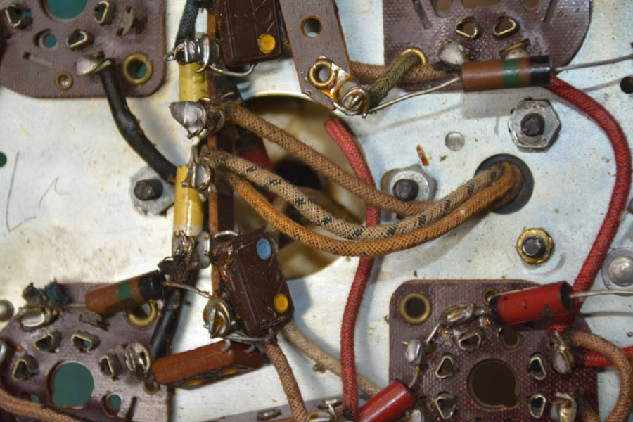
The three leads per the schematic are white with a black tracer, brown and red. There is no yellow. One of the .1's is connected to the Wht/Blk, the other end of that .1 is connected to ground. The other .1 is connected to Brown with the other end of the .1 connected to ground. One end of the .8 is connected to Brown, the other end is connected to Red. that is different than Nathan's description, so investigate carefully.
I think the red and the white/blk are connected together, with the white /blk and red connected to one of the 490K resistors and the Brown connected to the other 490K resistor.
Is that clear as mud? Look carefully at the Rider schematic as there is a detail of the part 89, 89A and 89B cap.
Here is a pic of the leads from the cap can:
Posts: 1,889
Threads: 214
Joined: May 2015
City: Seattle
State, Province, Country: WA
Very possible my interpretation of the wire colors isn’t a great reference. That was what they looked like on my set - but could have faded.
Users browsing this thread: 1 Guest(s)
|
|
Recent Posts
|
|
Studebaker/Philco AC-2687 car radio
|
| Arran,
Thanks for checking you manuals.
I appreciate that. Let me know what you find.
PhilPdouglaski — 08:46 AM |
|
Studebaker/Philco AC-2687 car radio
|
| I have some car radio service manuals, Riders I think (not to be confused with the big blue binders), so I may see if on...Arran — 01:20 AM |
|
Philco model 40-100
|
| Greetings;
Here is an update, I found a listing on fleabay for a similar chassis to yours, and it has a photo of what...Arran — 12:58 AM |
|
Philco model 40-100
|
| Greetings;
I think I may have found a clue as to what is missing, from a search I made, there is a rear view of the c...Arran — 12:12 AM |
|
Philco model 40-100
|
| I recently acquired a Philco model 40-100 farm (battery) radio. The radio was in very good condition except the red on f...mhamby — 05:59 PM |
|
Studebaker/Philco AC-2687 car radio
|
| Hello, Richard
the radio is an AC-2687 Studebaker model. The Philco model is S -5323 and the chassis p/n is S-5523Pdouglaski — 11:52 AM |
|
48-482 rear panel help
|
| The 48-482 is an AC only set as well, featuring a power transformer. While the transformer shouldn’t get “hot”, it is ye...jrblasde — 11:12 AM |
|
Studebaker/Philco AC-2687 car radio
|
| I gave a Chrysler/MoPar car radio from 1954, it was made by Philco, and it uses two chassis, one has the power supply an...Arran — 11:06 AM |
|
48-482 rear panel help
|
| Hello keithchip. You could make a hardboard back for the set, but make sure you provide plenty of ventilation holes in ...GarySP — 11:04 AM |
|
Studebaker/Philco AC-2687 car radio
|
| Welcome to the Phorum, Phil! Lots of friendly help here to assist you along the way! Take care, - GaryGarySP — 10:55 AM |
|
Who's Online
|
There are currently 738 online users. [Complete List]
» 2 Member(s) | 736 Guest(s)
|
|
|

|
 
|


![[-] [-]](https://philcoradio.com/phorum/images/bootbb/collapse.png)


