Posts: 7,323
Threads: 270
Joined: Dec 2009
City: Roslyn Pa
Correct. It's the small most outer winding. It's also the one that fails via decay. It is there to create feedback to cause the oscillator to run. A bit like a regenerative receiver w/o the fones
When my pals were reading comic books
I was down in the basement in my dad's
workshop. Perusing his Sam's Photofoacts
Vol 1-50 admiring the old set and trying to
figure out what all those squiggly meant.
Circa 1966
Now I think I've got it!
Terry
(This post was last modified: 09-10-2020, 08:11 AM by Radioroslyn.)
Posts: 13
Threads: 1
Joined: Aug 2020
City: Corrales
State, Province, Country: NM
Terry,
Interesting. Very helpful. I’ll get back into the Philco in a day or two. I’ll let everyone know how it goes. Working on an AA6 now...finally recapping it.
R
Posts: 1,797
Threads: 55
Joined: Feb 2015
City: Roseville, MN
Yes, Terry, that's correct. I missed that. It's an oscillator in a tank circuit, no wonder it's touchy. I would also look at the cathode bypass cap. I once fixed an amplifier tremolo circuit that had a bad cathode bypass.
Posts: 7,323
Threads: 270
Joined: Dec 2009
City: Roslyn Pa
It is kind of a primitive circuit. The older sets (70) used two tubes to perform the mixing duties. Seems like there would be some interaction between osc frequency and the peak adjustment of the 1st IF. The 36 tube (tetrode) needs a suppresser grid but such was the technology in 1932. The generation sets used the 39/44 a full fledged pentode.
When my pals were reading comic books
I was down in the basement in my dad's
workshop. Perusing his Sam's Photofoacts
Vol 1-50 admiring the old set and trying to
figure out what all those squiggly meant.
Circa 1966
Now I think I've got it!
Terry
(This post was last modified: 09-10-2020, 10:36 AM by Radioroslyn.)
Posts: 1,222
Threads: 50
Joined: Oct 2017
City: Allendale, MI
For grins and giggles, I pulled my 71 off the shelf and looked at the oscillator signal on the scope taking the signal at the cathode. Beautiful sign wave at 1500 kc. Amplitude went down as I tuned lower. Plus the shape of the waveform degraded severely. The cathode resistor is original and measures 11k. I paralleled another resistor to bring the cathode resistor down to about 8.4 k. The cathode waveform on the low end of the dial increased substantially, though still distorted. At the high end of the dial, the waveform was good but with slightly less amplitude than without the resistor. I left it in the circuit cuz the radio seems work a bit better on the low end of the dial.
(This post was last modified: 09-10-2020, 05:11 PM by rfeenstra.)
Posts: 13
Threads: 1
Joined: Aug 2020
City: Corrales
State, Province, Country: NM
Fun. Good to know. My alleged 15K resistor (as marked) measured 12.5K, and ironically, I, too used a parallel resistor and ended up with 8.4K. My LO was then good to about a receive frequency of 600 khz before all reception stopped at lower frequencies, because the LO quit. But right now, the LO has quit totally (again) and the receiver is dead everywhere.
I sometimes wonder how the osc tube would respond to higher B+.
Anyway, I’ll get back to this sad little oscillator this weekend.
R
Posts: 1,222
Threads: 50
Joined: Oct 2017
City: Allendale, MI
I did have to rewind the oscillator coil on my 71.
Posts: 13
Threads: 1
Joined: Aug 2020
City: Corrales
State, Province, Country: NM
Was it fully open, or intermittent? My osc comes and goes at will. Since I’ve not pulled mine out, how many turns does it have? And what insulating material did you wind it on (separating the windings)?
Posts: 1,222
Threads: 50
Joined: Oct 2017
City: Allendale, MI
I don't remember. I probably looked at it and saw the typical green corrosion. If it wasn't bad yet, it would have been in the future. So I rewound it. Any Philco with the nitrocellulose insulation is suspect.
Posts: 1,222
Threads: 50
Joined: Oct 2017
City: Allendale, MI
Here is a before and after pic. The coil does not look bad as i don't see any green. But I probably figured it would go bad eventually.
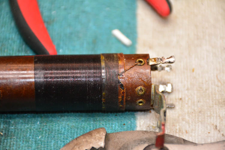
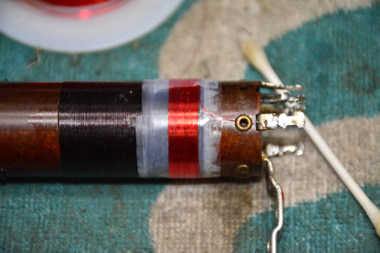
After the original winding was removed, the coil was baked and then sealed with lacquer.
Posts: 13
Threads: 1
Joined: Aug 2020
City: Corrales
State, Province, Country: NM
An update. The intermittent local oscillator refuses to quit, as usual, now that it’s on the workbench. I got it running by the usual ”shock excitation” method by touching the grid of the 36 osc/mixer with a short test lead. And now, it won’t quit. Plays for hours. When it finally does die, again, I’ll check voltages. But running properly, it has 90 Volts on the screen and about 260 on the plate...that should be more than enough to keep it oscillating.
Richard
(This post was last modified: 09-14-2020, 07:10 PM by WB5NEN.)
Posts: 7,323
Threads: 270
Joined: Dec 2009
City: Roslyn Pa
Is the feedback winding rewound? Same direction as original and wire ga around 38ga?
When my pals were reading comic books
I was down in the basement in my dad's
workshop. Perusing his Sam's Photofoacts
Vol 1-50 admiring the old set and trying to
figure out what all those squiggly meant.
Circa 1966
Now I think I've got it!
Terry
Posts: 13
Threads: 1
Joined: Aug 2020
City: Corrales
State, Province, Country: NM
Terry,
I have not rewound the feedback coil, because it shows good continuity. I have, however, thought about rewinding it just to get a few extra turns in a (probably foolish) attempt to provide more feedback. Once it quits again, and if I find voltages are still what they should be on the tube, I will also check the coil for continuity.
But if this sounds like I’m taking the wrong path, let me know!
Richard
Posts: 13
Threads: 1
Joined: Aug 2020
City: Corrales
State, Province, Country: NM
Update. I need my workbench cleared from the Model 71 woes. The 71 is still playing, the LO is (for the moment) still oscillating, and I am poor at troubleshooting a working circuit. I put the 71 back in the cabinet, put it in its permanent place, it’s still working, so I will move on to another project (replacing a busted belt on a console Zenith). Thanks to everyone. Sorry for the lack of resolution.
Richard
Users browsing this thread: 1 Guest(s)
|
|
Recent Posts
|
|
Philco P45-6365 Universal Transformer Instruction Manual
|
| Can anyone guide me to where this may be found?GRG — 03:00 PM |
|
54C Complete Teardown/Rebuild
|
| I don't think that I have encountered a 12Z3 before, curious how it uses one of those but includes a #43, which is a 25 ...Arran — 02:17 PM |
|
HiFi (Chifi) tube amp build - but my own design.
|
| It's the other forum. I'm also in DIY, but mostly read there. Honestly, I kinda jumped into this without much thought to...TV MAN — 10:43 AM |
|
Philco 71 Code 125
|
| Hello,
I am in need of a schematic for this radio. Mine has the three separate circular tube shields and a shadow me...dconant — 08:06 AM |
|
Stromberg Carlson 1500 Squeal
|
| And life just keeps getting more complicated.dconant — 07:57 AM |
|
54C Complete Teardown/Rebuild
|
| Hello Roy,
here is this one
sincerely Richardradiorich — 12:45 AM |
|
54C Complete Teardown/Rebuild
|
| Richard,
Had grabbed it already but thank you just the same. I find myself wanting to find some way to block out the...glyphmon — 12:03 AM |
|
54C Complete Teardown/Rebuild
|
| Hello roy,
here is a link to the schematic .
Sincerely Richardradiorich — 11:54 PM |
|
54C Complete Teardown/Rebuild
|
| Richard,
The Silvertone 2014 also is a transformerless set, so I am incorporating a 1:1 600 ohm audio isolation transfo...glyphmon — 11:37 PM |
|
Preliminary work on wife's Silvertone 2014
|
| Did an alignment today which was interesting. IF alignment went great, almost all was already spot-on. Adjusting on th...glyphmon — 11:35 PM |
|
Who's Online
|
There are currently 2435 online users. [Complete List]
» 1 Member(s) | 2434 Guest(s)
|
|
|

|
 
|





