Posts: 1,199
Threads: 49
Joined: Oct 2017
City: Allendale, MI
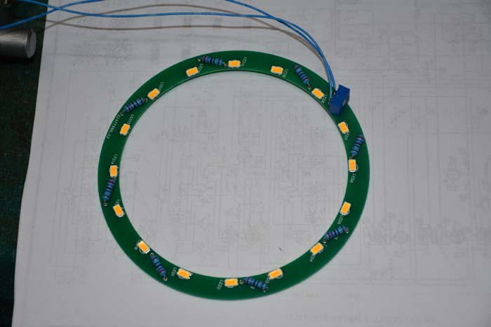
I printed the station tabs in the previous photo on ordinary photo paper. I need to find some printable, translucent material to print the tabs. The photo paper is very readable in normal light but not very translucent. When the "magnetic tuning" is ON, the tabs are supposed to be backlit by 2 lamps reflecting off from a reflector ring, the light passing through the shadow mask and the tuning dial before lighting the back of the tabs - not very effective, especially with the tabs printed on paper. So, a new, easily removable backlight system has been incorporated. I had a circuit board made that incorporates 16 LED's that is powered by the 6.3 volts from the magnetic tuning lighting system.

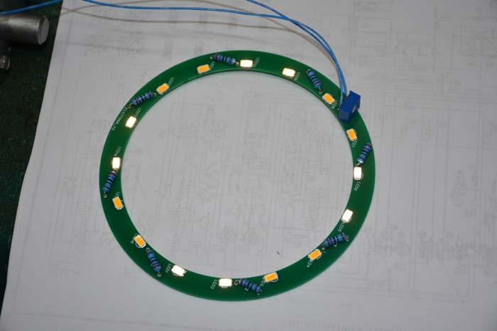
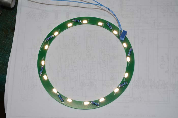
 The second photo indicates that half the LED's are dead. Not really! The LED's are powered from the AC voltage from the filament supply. 2 are in series that will light on the positive half of the AC, while the next 2 are series to light on the negative half of the AC . The LED's actually alternately flash on and off at 30 cycles per second. My shutter was set at 1/125 so it caught only half of the LED's lit. I do the alternating routine to reduce the apparent 30 cycle flicker. Next is a photo at 1/30. I thought that was interesting, but maybe it's only me!
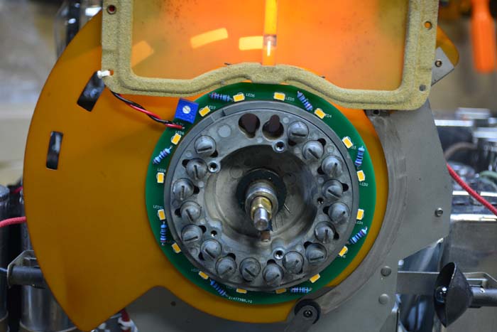
 Here's the system installed in the autotune system. It is in the space between the band selector shadow mask and the tuning dial.


Posts: 1,199
Threads: 49
Joined: Oct 2017
City: Allendale, MI
Posts: 816
Threads: 25
Joined: Mar 2014
City: Louisville, KY
Mmmmmmmmmmmmmmmmm....LOVE those dial lights and warm-colored dials!!! Thanks for sharing. 
Posts: 1,199
Threads: 49
Joined: Oct 2017
City: Allendale, MI
Posts: 1,824
Threads: 114
Joined: Jul 2014
City: Sneedville, TN
Where did you find that rubber? It might be useful for others who encounter a similar situation?
Posts: 1,199
Threads: 49
Joined: Oct 2017
City: Allendale, MI
I purchased a sheet of it on line from Home Depot.
https://www.homedepot.com/p/Rubber-Cal-C.../303197202
Very flexible but not as stretchy as just rubber.
Posts: 4
Threads: 1
Joined: Feb 2020
City: Portland
State, Province, Country: OR
Very nice job! I to will be restoring my 38-116 soon. The station tabs look amazing with the led light ring behind them. Did you have any extra circuit boards printed for making that light ring? What a slick idea.
Posts: 5,163
Threads: 273
Joined: Nov 2012
City: Wilsonville
State, Province, Country: OR
Great job!

Posts: 1,199
Threads: 49
Joined: Oct 2017
City: Allendale, MI
Been out of town for a couple of weeks - trying to enjoy sun and heat. But, happy to be back to the cold!
Nicko, I had several made as there was a minimum. Soldering the surface mount LED's is a bit of a trick but doable. I made a couple more as I will use one for the 37-116 a finished a year or so ago, and one for the 37-116 that is waiting to be restored.
By the way, welcome to the phorum!! I missed it the last couple of weeks. One gets addicted.
Rob
(This post was last modified: 02-16-2020, 03:27 PM by rfeenstra.)
Posts: 13
Threads: 3
Joined: Dec 2020
City: Pompton Lakes
State, Province, Country: NJ
Its internally grounded..Ohm it out.
Posts: 1,199
Threads: 49
Joined: Oct 2017
City: Allendale, MI
Thanks, Quick573. If I ever take this radio out of the cabinet, I will ohm it out. I have just never seen that in a control like this. But then, I'm not all that experienced with these.
Posts: 71
Threads: 5
Joined: Nov 2005
City: Beaver Falls
State, Province, Country: Pennsylvania
Nice work on the restoration! Yes, the ground connection is carried to the frame of the control, so it is grounded through the bushing; that saved one wire on the assembly.
I have my own 38-116 restoration to get back on; I either need to find another speaker for it, or have it reconed.
Tim KA3JRT
Users browsing this thread: 2 Guest(s)
|
|
Recent Posts
|
|
The list of my radio & TV collection!
|
| A little bit of positivity in our feed...
My new video...
Test - the Philco 16B vs Philco 37-116 de Luxe / Test - the ...RadioSvit — 12:14 PM |
|
Refinishing Ideas
|
| Thanks. I will look into.
Billpoulsbobill — 11:23 AM |
|
My Philco 37-116 Restore
|
| Why do the flood lights have 2 wires running to the shell of each light when the inner conductor only has one to each?
...dconant — 10:54 AM |
|
Philco 46-480 Electronic Restoration
|
| OOPS!!
if there is a "flag" running up the side of the tube that touches the shield, then yes, a shield belon...MrFixr55 — 10:03 AM |
|
Philco 46-480 Electronic Restoration
|
| Thanks for pointing out that shield! I will try to find out where else it may belong. I simply installed it back where i...jrblasde — 10:02 AM |
|
Philco 46-480 Electronic Restoration
|
| Very nice job. A real contrast between how easy the main chassis is to work on, vs how tightly the RF chassis is packed...MrFixr55 — 09:31 AM |
|
Philco 46-480 Electronic Restoration
|
| After sleeping on it, I believe the issue is that I may have forgotten to install a ground connection between the RF cha...jrblasde — 09:21 AM |
|
Refinishing Ideas
|
| Hi Poulsbobl,
I think that you could get away with it. In the Philco Library, there is a parts listand specs for sp...MrFixr55 — 11:54 PM |
|
Philco 46-480 Electronic Restoration
|
| The sleeving for the transformer arrived early, so I went ahead and finished reassembling. The chassis looks far better ...jrblasde — 10:15 PM |
|
Philco 610B oscillator wiring
|
| I don't know what you are referring to when you say "tube cathode ground". Ground is a connection to the chass...RodB — 05:56 PM |
|
Who's Online
|
| There are currently no members online. |

|
 
|


![[-] [-]](https://philcoradio.com/phorum/images/bootbb/collapse.png)


