EH Scott Philharmonic AM/FM
Posts: 1,824
Threads: 114
Joined: Jul 2014
City: Sneedville, TN
Wow ! Congratulations, RF ! That is some great work ! Just looking at the underside of that chassis gave me the willies. That was some great perseverance and accuracy to get it all right with such minor problems ! All that new chrome looks great too. You've brought back one IMPRESSIVE radio.
Posts: 330
Threads: 30
Joined: Aug 2017
City: Hay Lakes, Alberta,Canada
WOW!! Amazing work!
If you are bothered by the green colour of the replacement resistor for the Candohm, you could use a bit of flat black high temp paint on it. BBQ paint works well.
Posts: 1,199
Threads: 49
Joined: Oct 2017
City: Allendale, MI
I may just do that! I touched up the IF just by ear and things are starting to work great. I'll hook up the spectrum analyzer to do a fine tuning and watch the response curves as I vary the selectivity. See if I can get respectable looking response curves. This thing has audio power! But I guess I can expect that from 4 6L6's. I think it will out do the BOL Philly I always listen to. The 6L6's run hotter on this one so I suspect the bias is set up a little hotter. I'll have to do some checking.
(This post was last modified: 02-10-2021, 10:51 AM by rfeenstra.)
Posts: 1,199
Threads: 49
Joined: Oct 2017
City: Allendale, MI
I've begun a "serious" alignment. I've started with the IF. This radio has 4 IF transformers. Selectivity is controlled by varying the center frequency of all of the primary and secondary IF transformers except the primary of the first and the secondary of the forth - stagger tuning accomplished by a single shaft controlling 6 3-plate variable caps. 3 increase capacity and 3 decrease capacity as the selectivity control is turned. The IF is peaked in the most selective position of the control. Then, as the selectivity control is turned, the various stages are detuned to broaden the response curve the IF system. It seems, from my experience here, that it is very difficult to get an even transition from most selective to broadest frequency response. I'm having trouble keeping the response curve fully centered on the IF frequency of 465 kHz. This forces me to retune when I go from very selective to very broad frequency response. I'm thinking there will be compromises!
As the response curve broadens for higher fidelity, the sensitivity naturally goes down so Scott included a variable control on the selectivity that changes the bias voltage on the AGC system to compensate.. It's not perfect, but does a pretty good job of compensating.
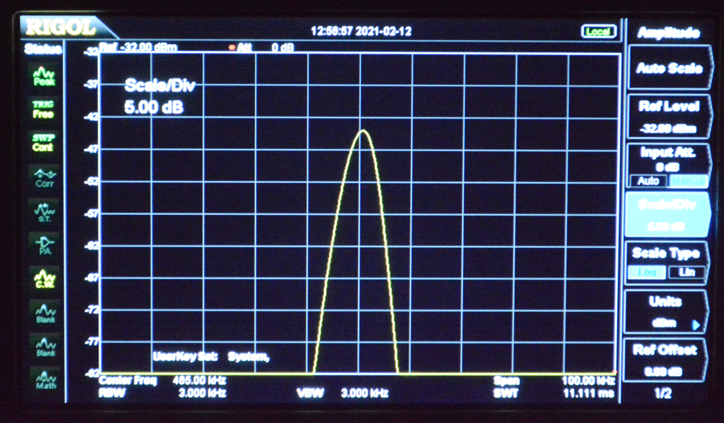
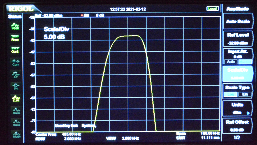
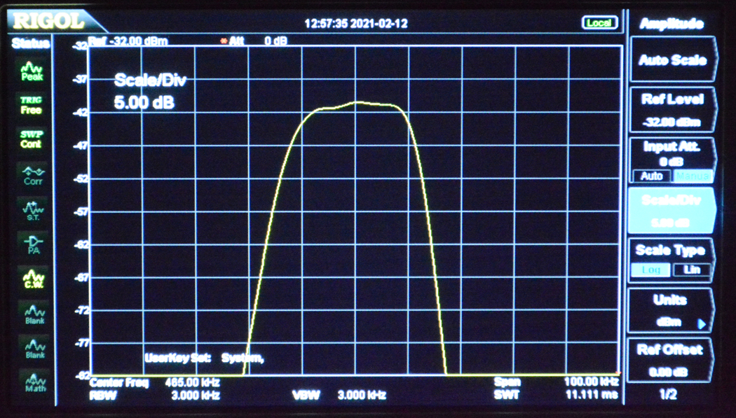
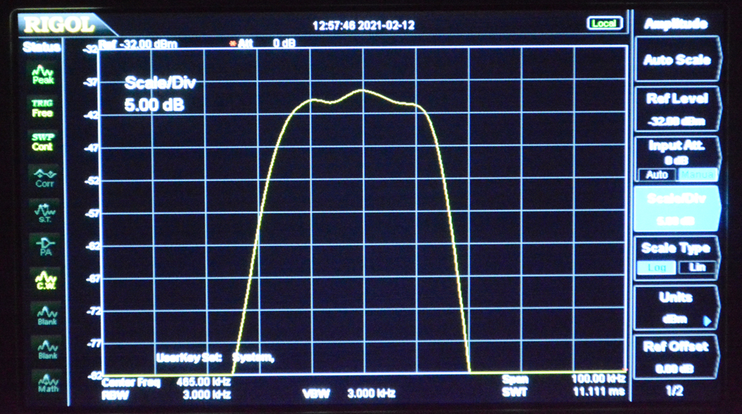
A spectrum analyzer is very useful in this process as I can see every very slight change in the response curve as I change the adjustments. I need to figure out how to keep the center frequency at exactly 465 kHz at all positions of the selectivity control. I may have to tweak the 6 variable caps individually. Could be hours of playing/experimenting. Fun, right!?
Following are a few pics of the Spectrum Analyzer at various positions of the selectivity control from highest selectivity to broadest frequency response. 10 kHz/division horizontal, 5 db/division vertical. You can see the curve broaden out as i turn the control to max fidelity. I just need to make everything more symmetrical. Fun Stuff!!

(This post was last modified: 02-16-2021, 08:50 PM by rfeenstra.)
Posts: 1,199
Threads: 49
Joined: Oct 2017
City: Allendale, MI
I kept tweaking today and I think I have it where I'm happy. It stays fairly centered on the IF frequency and the curve quite symmetrical. To get it there, I had to compromise a little on sensitivity. But then there is a LOT of sensitivity in these radios. Losing a little won't affect how I use the radio. It is really sounding great with my HiFi transmitter. Bass is a bit lacking with the speaker out of the cabinet. I've tuned up the IF AGC and the RF AGC. Now on to the RF section.
Posts: 1,199
Threads: 49
Joined: Oct 2017
City: Allendale, MI
I finished the RF section Friday. Most of the bands line up pretty good, though mid band on a couple of bands are off by about 4 kHz. Not bad but on a radio like this, I would like it spot on. To do that I would have to increase or decrease coil inductance by spreading or pushing coil windings together, a Scott described process that is evident on some coils from original Scott tuning. I don't really want to mess with that. Today (actually yesterday - it's after midnight!) I got the FM all aligned. I followed the Scott recommended procedure and verified with the spectrum analyzer. The discriminator took the most time. Getting the output as linear as possible took a bit of back and forth tweaking. It seams to be very close from +80 kHz to -80 kHz modulation. Beyond that, linearity suffers a bit. But FM is limited to +-75 kHz so should be ok. Scott says +-80 is good, but it's nice to to get +-100 kHz in case a station likes to over modulate. A little non-linearity over +-75 kHz translates to a bit of distortion on over modulated signals.
One of the guys on the Scott forum has a converter available to use the FM band. I have one coming. It's really an FM receiver whose output is at 45 mHz and ties directly to the FM antenna connections. The alternative that I've seen is a TV tuner converted to receive in the FM band with a fixed local oscillator and a wide band output. This allows one to use the Scott tuner from 42 to 50 mHz. The problem is that the converter has to use 3 "channels" because you cannot get the the wide band output wide enough to cover the whole FM band. So you have 1/3 of the FM band with each TV tuner channel. A chart of conversion frequencies is necessary to know where on the Scott tuner you would tune to get a certain frequency. This is how the original converter systems worked that were provided when the FCC changed the FM band in about 1946. With the converter I bought, that process won't be necessary. Yet, I won't be twisting the Scott knob to change stations! Doesn't seem quite right. With the unit I purchased, one could easily ask, "Why not just purchase an FM tuner with audio out and connect it to the phone in?" A legitimate question that I considered. But, for some less than fully reasonable reason, I want to utilize the full FM section of the Scott receiver, just because I rebuilt it so I want to use it! It should sound great.
So far, all is very good. The switch for the "noise filter" is broken internally, and the volume control has a bit of static at very low volumes. The noise filter is fairly useless so I'm not to worried about replacing it, and the volume control can be replaced, though it really doesn't bother much.
Posts: 1,824
Threads: 114
Joined: Jul 2014
City: Sneedville, TN
Hi R.F. !
I read your latest post. Congratulations on all your work on this magnificent radio ! It got me thinking, and that got me hunting on the net. I found a few sites that might be of help or interest you you:
http://userpages.bright.net/~geary/fm/fmconverter.html
http://www.theradiofox.com/fm/fmconverter.html
https://antiqueradios.com/forums/viewtop...&p=2416131
https://antiqueradios.com/forums/viewtopic.php?t=147062
That last link has a link in it to a Russian site that has an old Popular Mechanics article on how to make a converter for the old to new FM bands. Hope you find them at least interesting, if not useful. And last, here is a link to download that Popular Mechanics article in case you feel like trying it, and one to another Popular Mechanics article from 1946 on a different converter you could build, They are both PDFs, so you can DL them if you want.
http://www.vacuumtubeera.net/FM-Converte...Device.pdf
http://www.vacuumtubeera.net/One-Tube%20...y-1946.pdf
(This post was last modified: 02-14-2021, 04:57 AM by mikethedruid.
Edit Reason: added another link
)
Posts: 1,199
Threads: 49
Joined: Oct 2017
City: Allendale, MI
Thanks Mike! I've seen a couple of those articles in my investigation. I've even tried to PM Penthode to see if he is still converting the "subbers" I have 2 that I would like converted. Or, I'll learn to do it myself. That system, along with the ordinary TV tuner appears to be the better, more sensitive solution. For now, I'll use the one I purchased from Bill on the Scott site. It could be fun to experiment with the subbers I have.
Posts: 1,199
Threads: 49
Joined: Oct 2017
City: Allendale, MI
The FM has been aligned, though all of the tubes are on the edge of or below minimum strength. There is a very knowledgeable person on the Scott forum who says the FM tubes need to be well above the minimum for the system to work quietly. I have NOS tubes coming. But for now, it is working. The converter from this same person arrived and I have it in use. The radio sounds great on FM. The converter allows me to tune the entire FM band, setting the desired frequency on the converter, then fine tuning with the Scott dial set at around 45 mHz. OR, I can set the frequency on the converter to one frequency and tune about a third of the FM band on the Scott tuner. This requires a calculation to know what frequency I am tuning in. It takes 3 such settings to tune the entire band (old band is 8 mHz wide and the current band is 20 mHz wide). Interestingly, because the converter local oscillator is above the desired frequency, you tune the Scott dial lower to tune in a higher frequency in the FM band. There is something satisfying about tuning the Scott dial all the way across rather than having it set at one frequency! A bit more knob twisting though. When I get the NOS tubes, I'll redo the entire FM alignment.
This complex radio is almost finished. I'll do a bit of work on cleaning up the cabinet but will not refinish it, It's pretty good. Then install the radio. That will help the bass response tremendously. I may even try to figure a way to add tweeters as that was an option back in in the day. Then it should match the Beam of Light Scott Philharmonic that I listen to regularly. Great radios.
Posts: 1,824
Threads: 114
Joined: Jul 2014
City: Sneedville, TN
Congratulations, RF ! It is always a great feeling of satisfaction when a project you have worked hard on turns out well.
Posts: 1,199
Threads: 49
Joined: Oct 2017
City: Allendale, MI
Thank you, Mike. I think it is satisfying any time you take something not working and make it work again. This is the most complex radio I've worked on and is especially satisfying to get it working so well, especially without major problems of my own making!
The FM converter is working very well. I am enjoying listening to music on various local FM stations from classical to rock and from my own FM transmissions streaming from my DAW. Interestingly, the audio from my HiFi AM transmitter sounds indistinguishable from the FM sound when I have the AM selectivity in the broadest position. FM is a tiny bit quieter. The AM transmitter is not really a transmitter, rather a micro AM rf source modulated from about 20 Hz to 15 kHz. I can connect it directly to the AM antenna connection of the radio and disconnect the long wire to eliminate outside AM signals. All of the HiFi AM radios sound great, including the Philco 37-116, from this source.
Perhaps I'll make a couple of videos to show the AM portion including the short wave bands, the FM with the converter, and, perhaps, demonstrating the variable selectivity control - how it works, how it changes the sound, and how it affects selectivity. I'm just not much into videos! Maybe I can Buzz to help!!
(This post was last modified: 02-17-2021, 06:25 PM by rfeenstra.)
Posts: 4,440
Threads: 419
Joined: Jun 2011
City: Boston
State, Province, Country: Massachusetts
Yes ask Buzz and Dickel to assist in the production  .
Paul
Tubetalk1
Posts: 1,199
Threads: 49
Joined: Oct 2017
City: Allendale, MI
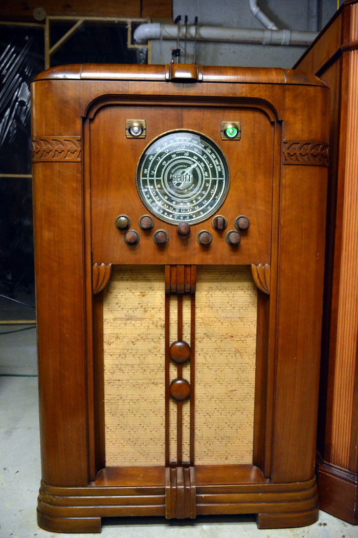
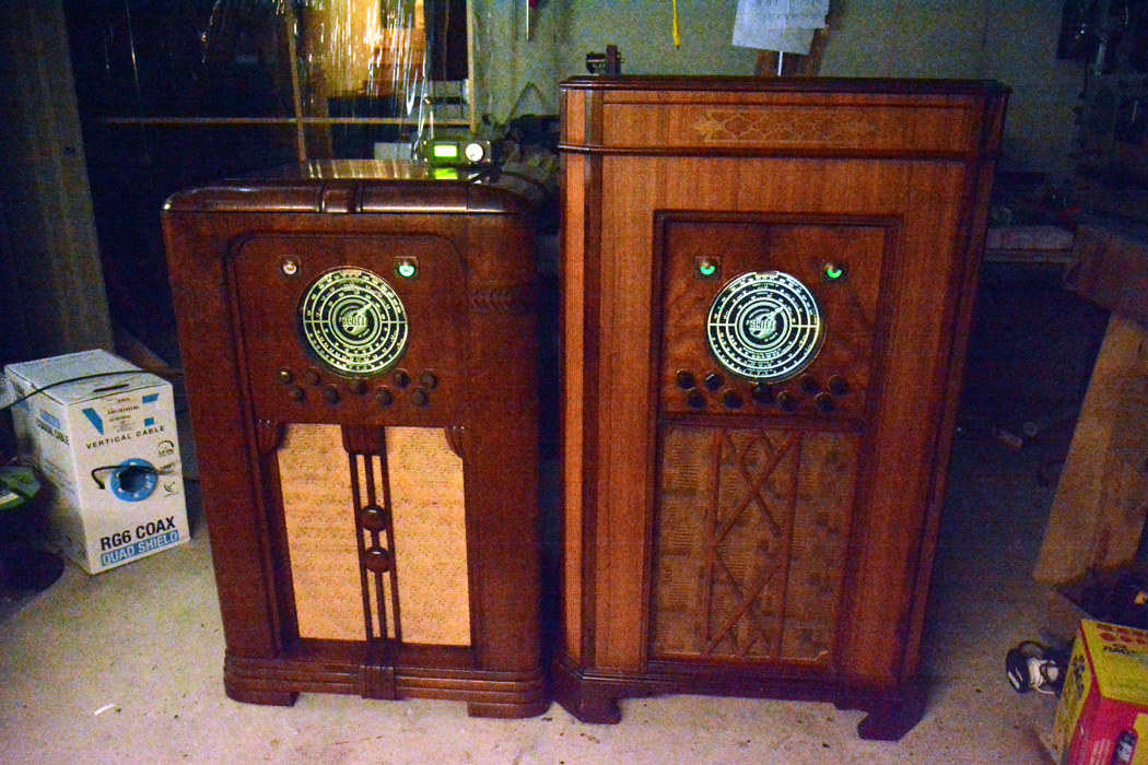
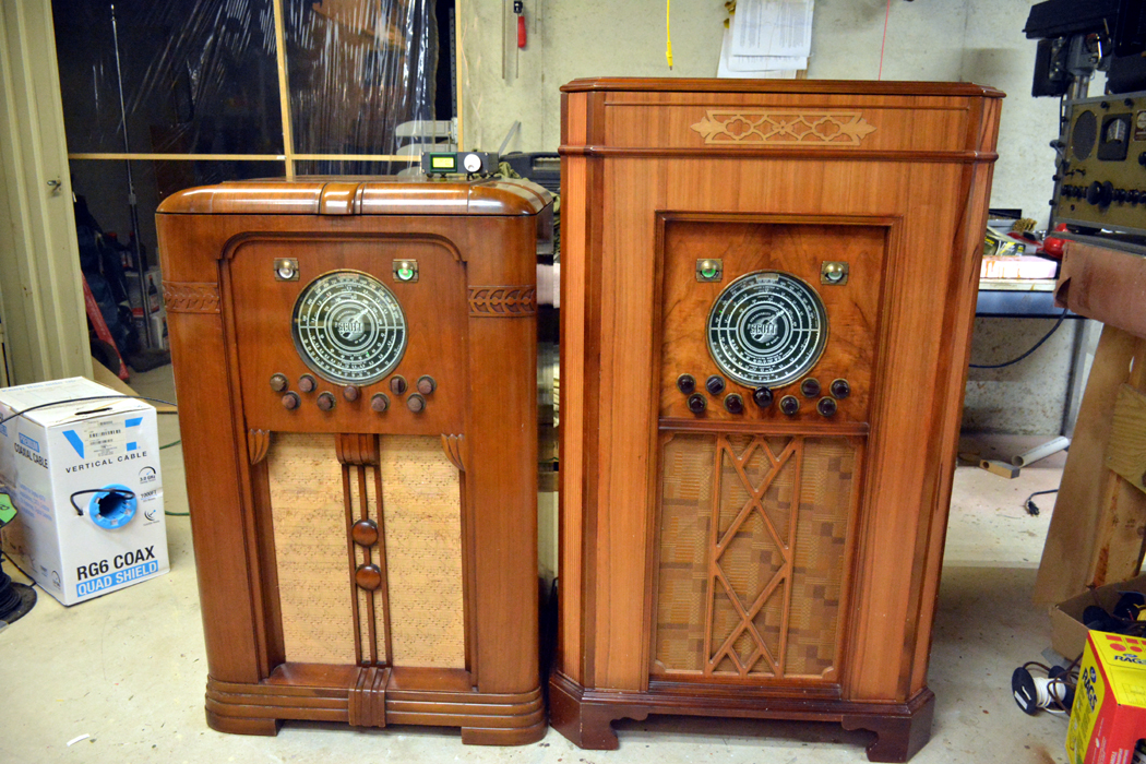
Still waiting for some new tubes for the FM but couldn't resist installing it in its rightful place. Sounds even better with the speaker in the cabinet. For the moment, I have the two Philharmonics side by side in the shop. The right one is the Beam of Light Philly I purchased at the Stanton auction last March, the left one is the AM/FM I purchased from Ron, the subject of this thread. The AM/FM is on the FM band with the converter setting on top allowing me to tune the FM band. You will notice that only one of the eyes is lit. The left one is for AM tuning and the right one is for FM tuning. On the BOL Philly, both eyes are lit. The left one is for tuning and the right one gives indication of the amount of expansion when the Expander is engaged. I need one "pinch" type Scott wooden knob for the AM/FM. I hear they are not easy to come by. I may have to steal one from my Scott 16.
I took one picture with the lights dimmed a bit to show off the dials.
Posts: 3,152
Threads: 56
Joined: Apr 2011
City: Lexington, KY
That's a beautiful pair, great job 
John KK4ZLF
Lexington, KY
"illegitimis non carborundum"
Users browsing this thread: 1 Guest(s)
|
|
Recent Posts
|
|
Philco 39-7C Restore
|
| A little more work today. I got the first IF transformer back together after replacing the wiring going to the 78 tube ...klondike98 — 12:06 AM |
|
Two small radios from France. Restoration and review.
|
| And here they are, the French beauties ready:
In summary, the suspicion that radio transmits the national cha...Vlad95 — 10:46 PM |
|
Two small radios from France. Restoration and review.
|
| One is ready for washing, the other for painting:
ATTENTION
Faint-hearted and heart patients,
please d...Vlad95 — 10:36 PM |
|
Two small radios from France. Restoration and review.
|
| Range Switch Block:
I thought that mica capacitors of this type died out in the 30s, but no, they just moved ...Vlad95 — 10:29 PM |
|
Two small radios from France. Restoration and review.
|
| Chassis bottom view:
Again, like twins, especially in the range switch part.
Front panels:
And...Vlad95 — 10:25 PM |
|
Two small radios from France. Restoration and review.
|
| Chassis removed, front view:
Chassis rear view:
It will be enough for the first device to prescribe a bath.
Bu...Vlad95 — 10:11 PM |
|
Two small radios from France. Restoration and review.
|
| France
Peculiarities of national character.
Excelsior-52 threw me off track. It was too far outside my established...Vlad95 — 10:06 PM |
|
Philco 16b no shortwave reception
|
| First let thank everyone who helped ID this radio a few weeks ago!
I have replaced all the capacitors and was able to r...Ken D. — 08:07 PM |
|
Philco model 38 code 121 not receiving signal.
|
| Ah yes, the Philco "Green Death" strikes again, someone suspected that cellulose nitrate based insulation migh...Arran — 06:23 PM |
|
Philco model 38 code 121 not receiving signal.
|
| Not sure if it matters much, but measure where the winding sits on the tube and try to rewind as close as possible. Tak...GarySP — 05:45 PM |
|
Who's Online
|
| There are currently no members online. |

|
 
|


![[-] [-]](https://philcoradio.com/phorum/images/bootbb/collapse.png)


