New member with 37-650 Questions
Posts: 23
Threads: 2
Joined: Mar 2021
City: Philadelphia
State, Province, Country: Pa
Hi,
Thank you all for your time and reading my post. I just recently purchased a Philco 37-650 that I'm working to restore. I picked up this hobby mostly because I enjoy woodworking and wanted to restore the cabinet. My first radio I restored a few months ago was a Zenith 8s463. I wasnt sure about restoring the chassis because I never worked with electronics but after receiving a quote for $1700 to recap I decided to give it a try. The chassis was a success and I also installed an MP3 jack. With that I'm starting to enjoy the electronic part over woodworking.
This is all a learning experience for me as I've been trying to read and pickup as much knowledge as I can. I joined this forum because I have some questions regarding this chassis as I have had 2 ECAPS ( c59, 10mfd) explode on me. I'm reaching out for any help to see where I'm going wrong.
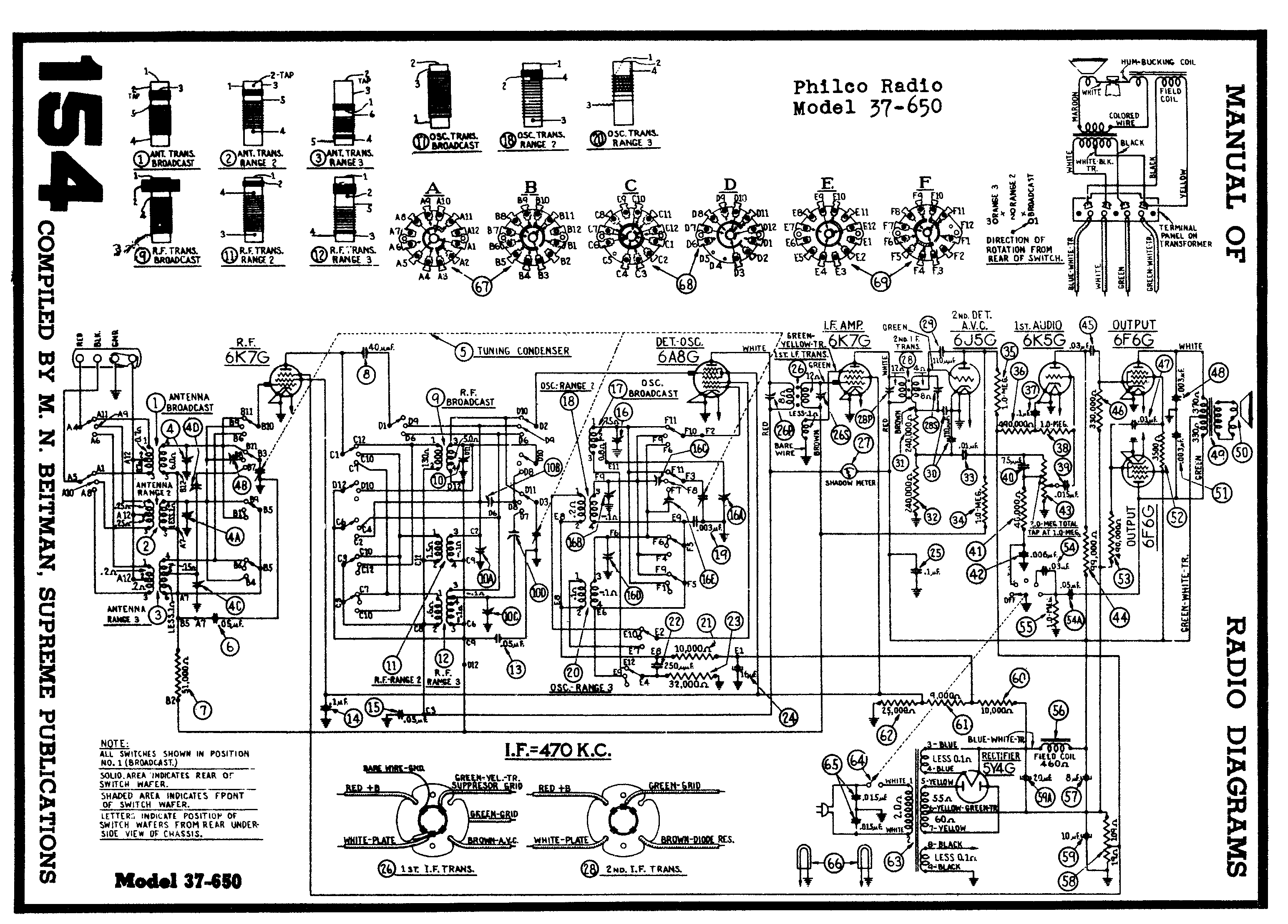
All 3 ECAPS (C59,C59A,C57) I have connecting to a terminal strip rather that repacking. All three negatives are being tied together to the bias resistor and the CT. The positive ends of the C57 & C59A I have going to the B+ of the field coil. C59 (which keeps exploding) I have going to chassis ground. I'm still trying to understand positive going to ground. I believe I'm following the print but the results disagrees. In addition I'm noticing the detector, RF & IF tubes are not lighting. The radio wasnt working when I bought it. When I first powered up there was no sound. Could anyone validate my wiring for these 3 ECAPS specifically C59 positive going to ground.
Thank you all again.
Posts: 3,152
Threads: 56
Joined: Apr 2011
City: Lexington, KY
Welcome to the Phorum 
If you post your question under the Philco Electronic Restoration section you'll get more responses. If no one replies before I get back home I'll look up that schematic.
John KK4ZLF
Lexington, KY
"illegitimis non carborundum"
Posts: 5,166
Threads: 273
Joined: Nov 2012
City: Wilsonville
State, Province, Country: OR
Welcome to the Phorum!

As John mentioned, you can post the electronics question in the Electronic Restorations section. Keep all of this radios Electronics Question in one thread.
What I see is the negative terminal of C59 goes to chassis ground and the positive terminal goes to the center tap of the transformer secondary. EDIT: See the info in following posts...re: incorrect schematic.
[Image: https://www.dropbox.com/s/vhqze85ywphcgm....jpg?raw=1]
Posts: 1,259
Threads: 32
Joined: Jan 2014
City: Wellborn Florida

Welcome to the Phorum, some info from Beitmans
Posts: 1,411
Threads: 72
Joined: Oct 2007
City: Linn Creek, MO
Hi and welcome!
The schematic is incorrect, the positive end of 59 goes to the chassis and negative to the HV center tap. Always remember the HV center tap is the most negative point in the circuit.
Steve
M R Radios C M Tubes
Posts: 16,495
Threads: 573
Joined: Oct 2011
City: Jackson
State, Province, Country: NJ
It is a mistake in the sch. C59 should have negative to the centertap and positive to GND.
People who do not drink, do not smoke, do not eat red meat will one day feel really stupid lying there and dying from nothing.
Posts: 7,300
Threads: 268
Joined: Dec 2009
City: Roslyn Pa
Hi neighbor
59 the + connects to the chassis and - to the hv ct. There's not much voltage there so a 35 or 50v cap is fine. No need for a 450v unit.
GL
When my pals were reading comic books
I was down in the basement in my dad's
workshop. Perusing his Sam's Photofoacts
Vol 1-50 admiring the old set and trying to
figure out what all those squiggly meant.
Circa 1966
Now I think I've got!
Terry
Posts: 13,776
Threads: 580
Joined: Sep 2005
City: Ferdinand
State, Province, Country: Indiana
klondike98 Wrote:...you can post the electronics question in the Electronic Restorations section.
...or we can just move this thread there (here). Done. 
Welcome Chinook47. I have to ask, but you do not have to answer - who in the world quoted you $1700 to repair/restore your 37-650? That's insane! Good that you decided to repair it yourself. There are lots of good folks here who can help by answering your questions.
--
Ron Ramirez
Ferdinand IN
Posts: 5,166
Threads: 273
Joined: Nov 2012
City: Wilsonville
State, Province, Country: OR
Thanks for setting me straight on that incorrect schematic!! I should have realized that. 
Posts: 23
Threads: 2
Joined: Mar 2021
City: Philadelphia
State, Province, Country: Pa
Thank you all for everyone's replies. Everyone is very helpful. I will post my question under the electronic restoration section. Before leaving this thread just to answer some of the questions, first I agree $1,700 to recap was insane. The place was a small business outside of Philadelphia. Lastly, I currently have the C59 positive going to chassis ground but the cap is still exploding. Perhaps my wiring is incorrect.
Thank you all again for your replies.
Posts: 7,300
Threads: 268
Joined: Dec 2009
City: Roslyn Pa
Make sure you don't have the - side of 59 connected to the + side of 59A or 57. That will make it go BANG!!! And the 5Y4 will hate you too.
When my pals were reading comic books
I was down in the basement in my dad's
workshop. Perusing his Sam's Photofoacts
Vol 1-50 admiring the old set and trying to
figure out what all those squiggly meant.
Circa 1966
Now I think I've got!
Terry
Posts: 713
Threads: 8
Joined: Apr 2018
City: S. Dartmouth
State, Province, Country: MA
Cap #59 would "explode" if resistor #58 were defective or its ground connection poor. Do not trust riveted ground tabs to work properly after 70 years. Solder 'em or drill out and bolt 'em...
Pliny the younger
“nihil novum nihil varium nihil quod non semel spectasse sufficiat”
Posts: 5,166
Threads: 273
Joined: Nov 2012
City: Wilsonville
State, Province, Country: OR
Your thread was moved by a moderator so all you need to do is continue with this thread! You are doing great.
Posts: 1,411
Threads: 72
Joined: Oct 2007
City: Linn Creek, MO
Quote:I currently have the C59 positive going to chassis ground but the cap is still exploding. Perhaps my wiring is incorrect.
Was this capacitor ever connected with a reverse polarity? If the cap has been improperly installed it will deform, then if reinstalled correctly, it could still explode.
OT. I have to ask, did you fly a Chinook?
Steve
M R Radios C M Tubes
Posts: 285
Threads: 27
Joined: Nov 2012
City: Tehachapi. California
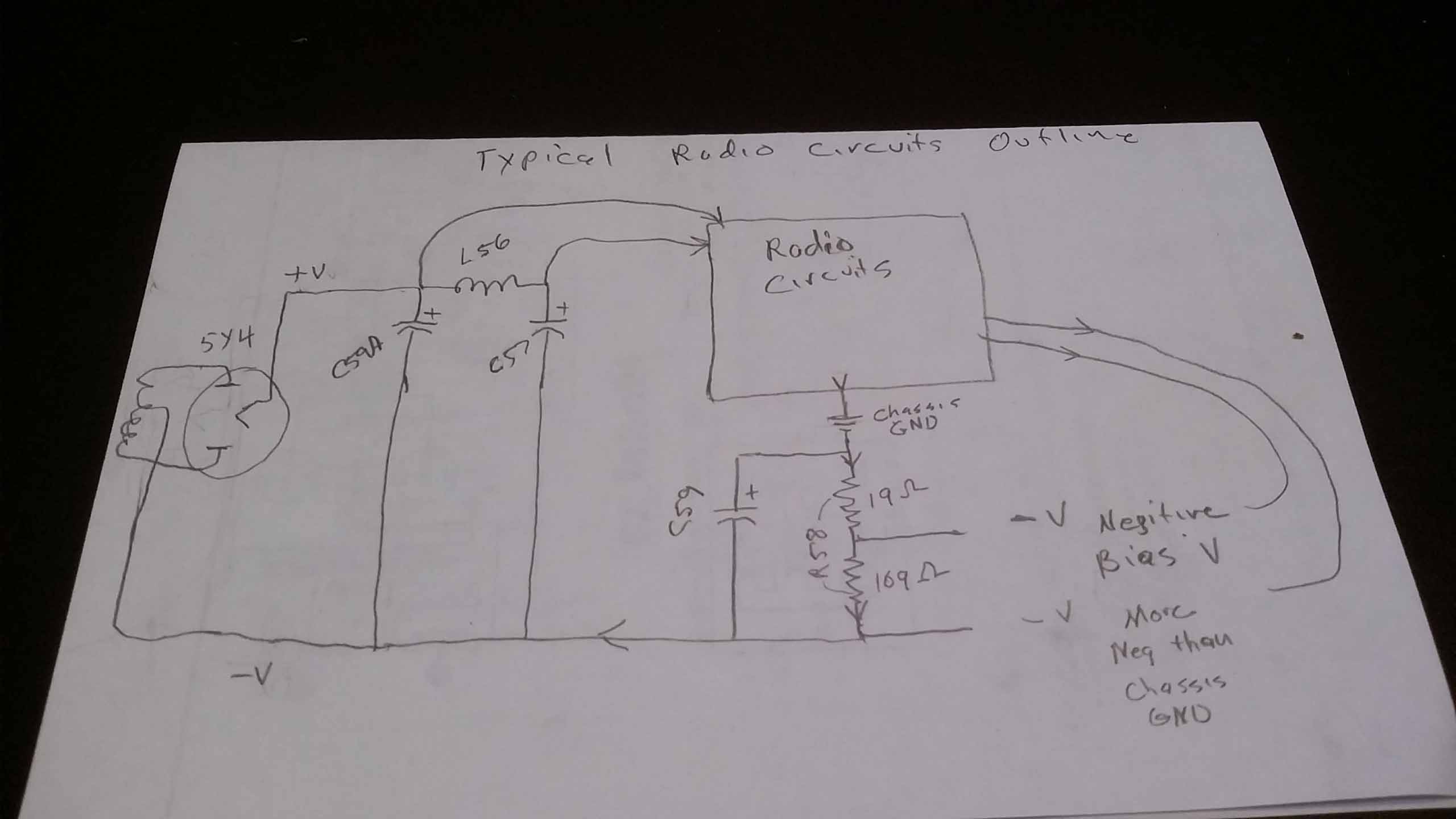
Maybe this will help with what's going on with capacitor #59 and why it's looks backwards.
One would think the chassis is the most negative point in the radio. but no. Redrawing the circuit.

As Chas stated if the resistor divider #58 is open the voltage across C59 will rise up alot.
!!!!!!!!!!!!!!!!!!!RESISTANCE IS FUTILE!!!!!!!!!!!!!!!!!!!!!!
/\/\/\/\/\/\/\/\/\
[Image: http://philcoradio.com/phorum/images/smi...on_eek.gif] Chris
Users browsing this thread: 1 Guest(s)
|
|
Recent Posts
|
|
Studebaker/Philco AC-2687 car radio
|
| Arran,
Thanks for checking you manuals.
I appreciate that. Let me know what you find.
PhilPdouglaski — 08:46 AM |
|
Studebaker/Philco AC-2687 car radio
|
| I have some car radio service manuals, Riders I think (not to be confused with the big blue binders), so I may see if on...Arran — 01:20 AM |
|
Philco model 40-100
|
| Greetings;
Here is an update, I found a listing on fleabay for a similar chassis to yours, and it has a photo of what...Arran — 12:58 AM |
|
Philco model 40-100
|
| Greetings;
I think I may have found a clue as to what is missing, from a search I made, there is a rear view of the c...Arran — 12:12 AM |
|
Philco model 40-100
|
| I recently acquired a Philco model 40-100 farm (battery) radio. The radio was in very good condition except the red on f...mhamby — 05:59 PM |
|
Studebaker/Philco AC-2687 car radio
|
| Hello, Richard
the radio is an AC-2687 Studebaker model. The Philco model is S -5323 and the chassis p/n is S-5523Pdouglaski — 11:52 AM |
|
48-482 rear panel help
|
| The 48-482 is an AC only set as well, featuring a power transformer. While the transformer shouldn’t get “hot”, it is ye...jrblasde — 11:12 AM |
|
Studebaker/Philco AC-2687 car radio
|
| I gave a Chrysler/MoPar car radio from 1954, it was made by Philco, and it uses two chassis, one has the power supply an...Arran — 11:06 AM |
|
48-482 rear panel help
|
| Hello keithchip. You could make a hardboard back for the set, but make sure you provide plenty of ventilation holes in ...GarySP — 11:04 AM |
|
Studebaker/Philco AC-2687 car radio
|
| Welcome to the Phorum, Phil! Lots of friendly help here to assist you along the way! Take care, - GaryGarySP — 10:55 AM |
|
Who's Online
|
There are currently 740 online users. [Complete List]
» 2 Member(s) | 738 Guest(s)
|
|
|

|
 
|


![[-] [-]](https://philcoradio.com/phorum/images/bootbb/collapse.png)


