Philco 95 - 1st RF Transformer issues
Posts: 7
Threads: 1
Joined: Jun 2021
City: London
State, Province, Country: ON
Hi all!
So recently I picked up a Philco Model 95 radio! It's in pretty good condition - at least on the outside 
Inside...
Philco 95 Gallery
It was dirty! A think layer of fine dust coated everything. I got all the tubes packed away - it did come with all of them! I brushed off as much of the dirt as I could.
Now on to the fun part 
I know it needs a total recapping. There are several newer caps, but most look original. I've found all the caps I need here: www.justradios.com
Is this a good source? Will I have any problem replacing all the caps with 630v metalized film caps? There are three that I need much smaller values than are available for film caps...50pF and 250pF - is it ok to use 500v dipped silver mica caps here?
I assume it also needs a full compliment of resistors...at least it will need something to replace this: 8300ohm Resistor
This appears to be a 8300 ohm resistor that has had some damage...the damage was all on the top of the resistor - looks like some arcing?
(This post was last modified: 01-17-2022, 08:09 PM by neil.)
Posts: 1,120
Threads: 44
Joined: Feb 2015
City: Roseville, MN
Hi and welcome to the Phorum. So you can get your caps from quite a few good sources and which ones depends on how many radios you intend to restore. If you have several or more then buying the most used values in bulk (quantities of 10 or more) is the way to go. Your unit price will be close to half. If you're buying for one or two then you are on the right track. Yes, stay with the 630 volt film. The 8300 ohm resistor is a wire wound so try to find a similar wire wound at 10 watts (maybe 8000 - 8200). The rest of the resistors can be tested and if they are more than twenty percent out of tolerance (I use 10 percent) then replace them. Feel free to run any questions at the Phorum. You'll probably get more than one correct answer. GL with your 95.
Posts: 16,476
Threads: 573
Joined: Oct 2011
City: Jackson
State, Province, Country: NJ
Wow. This radio was last repaired in 50-s. At that point these were often simply tossed. Someone was pretty fond of it.
And the exterior has been preserved remarkably well.
People who do not drink, do not smoke, do not eat red meat will one day feel really stupid lying there and dying from nothing.
Posts: 2,118
Threads: 112
Joined: Jun 2010
City: Medford OR (OR what?)
I used to by caps from Just Radios. Nothing at all wrong with them. Later I began ordering in quantities of 50+ which I have been getting from Sal (link on ARF). Sal has some 500V electrolytics (FYI). BUT, a lot of restores would rather buy name brand electrolytics from Mouser. I think that the little 630V yellow caps are about the same anywhere.
As I recall, this radio has an additional RF amp. Mine is very sensitive on a short antenna.
My 95
Well. maybe not.
Doesn't seem to be a way to post a picture - now.
Russ
"I just might turn into smoke, but I feel fine"
http://www.russoldradios.com/
(This post was last modified: 07-09-2021, 07:00 PM by Phlogiston.)
Posts: 5,162
Threads: 273
Joined: Nov 2012
City: Wilsonville
State, Province, Country: OR
Russ I asked Nathan to check into the picture posting issue. Thanks!
Posts: 7
Threads: 1
Joined: Jun 2021
City: London
State, Province, Country: ON
What are these:

The wiring diagram lists them as "compensating condensers", part # 3772-A...
Posts: 1,120
Threads: 44
Joined: Feb 2015
City: Roseville, MN
Looks like a mica capacitor. There's a thin slice of mica between the metal plates. If you trace the wires back then check the schematic to find the correct value. Looks like one side is soldered to gnd.
Posts: 13,776
Threads: 580
Joined: Sep 2005
City: Ferdinand
State, Province, Country: Indiana
"Compensating condenser" is correct. Also known as a trimmer capacitor.
--
Ron Ramirez
Ferdinand IN
Posts: 2,118
Threads: 112
Joined: Jun 2010
City: Medford OR (OR what?)
SO - - are the pictures supposed to be really huge (now)?
It's like a close-up. I think that I can see a mouse's nose-hair - from the 1960s - brown, I believe. Now where did the emojis go?
"I just might turn into smoke, but I feel fine"
http://www.russoldradios.com/
Posts: 1,106
Threads: 88
Joined: Jun 2011
City: Tacoma
State, Province, Country: Washington
Depends on what size pic you upload.
Posts: 7
Threads: 1
Joined: Jun 2021
City: London
State, Province, Country: ON
These are all taken with a macro lens ;)
Posts: 1,256
Threads: 32
Joined: Jan 2014
City: Wellborn Florida
Have a old 3g flip phone that i take pics with for the internet not the best but do not have to resize pictures. Take Care David
Posts: 7
Threads: 1
Joined: Jun 2021
City: London
State, Province, Country: ON
 01-13-2022, 11:34 AM
I've got this old Philco 95 that I am restoring!
Now that I have actually gotten around to it...there are a few more problems here than I had originally thought 
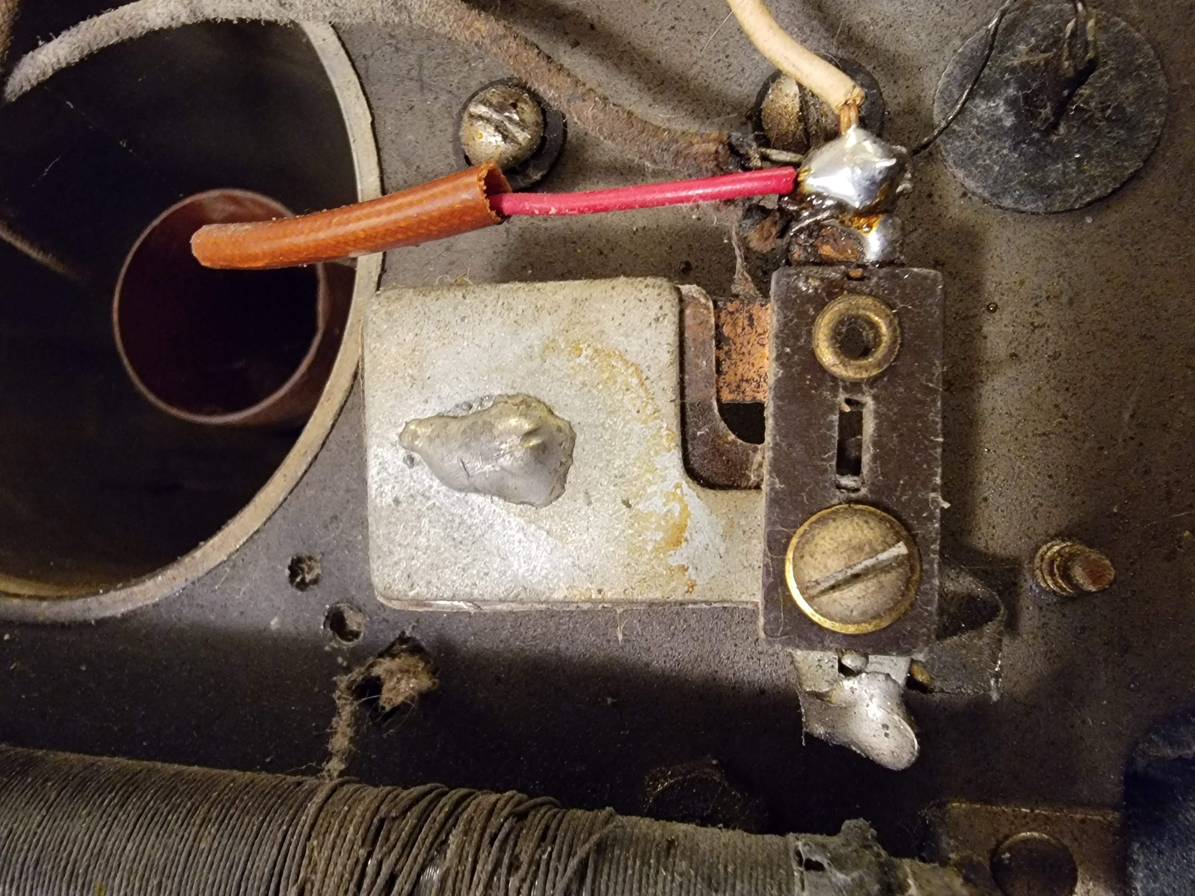
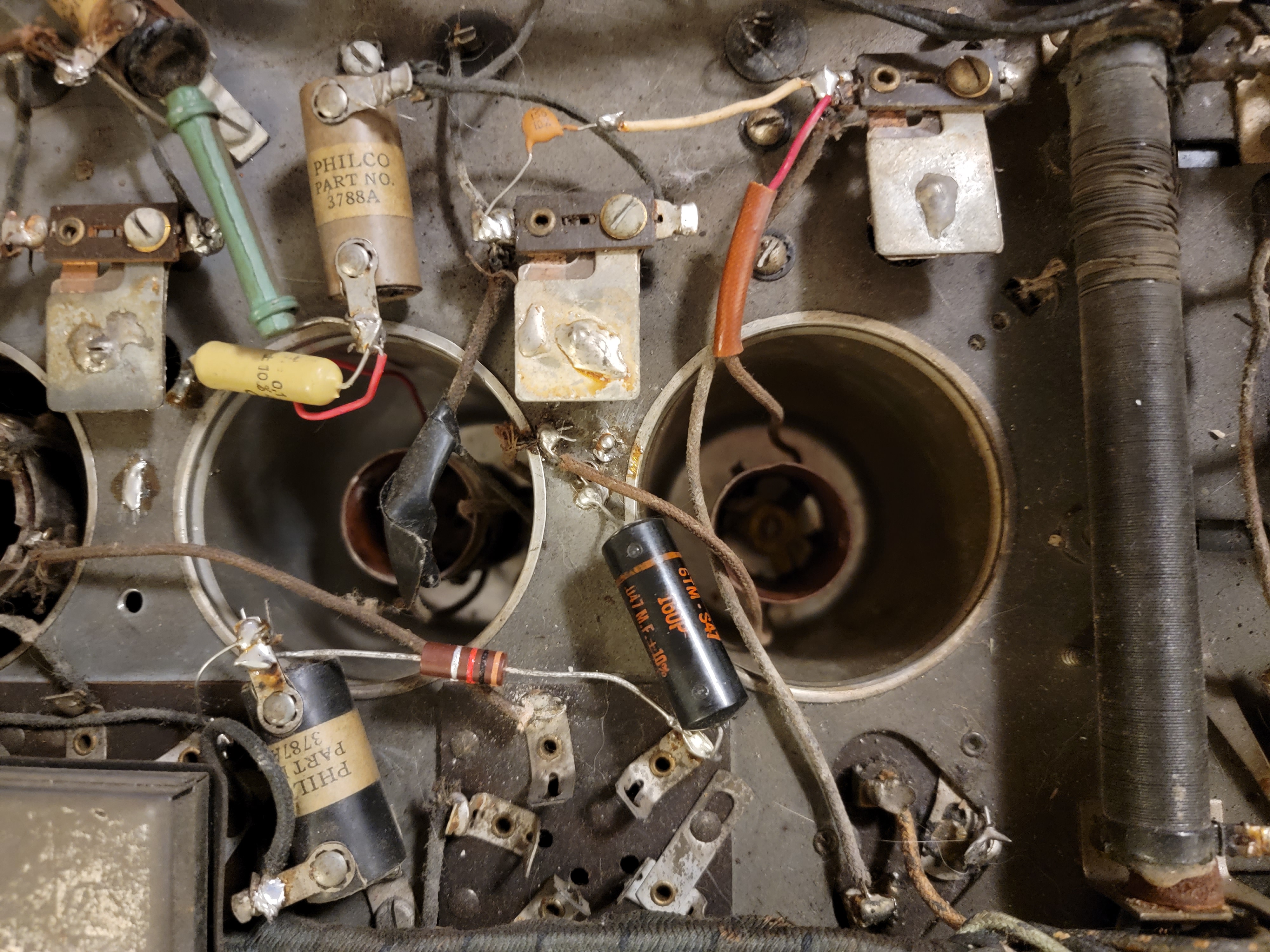
Any idea what has been done to the rf transformers? Specifically, it's the first two that I am on now...

They have been attached to the top of the cans, instead of at the bottom (like the other two).
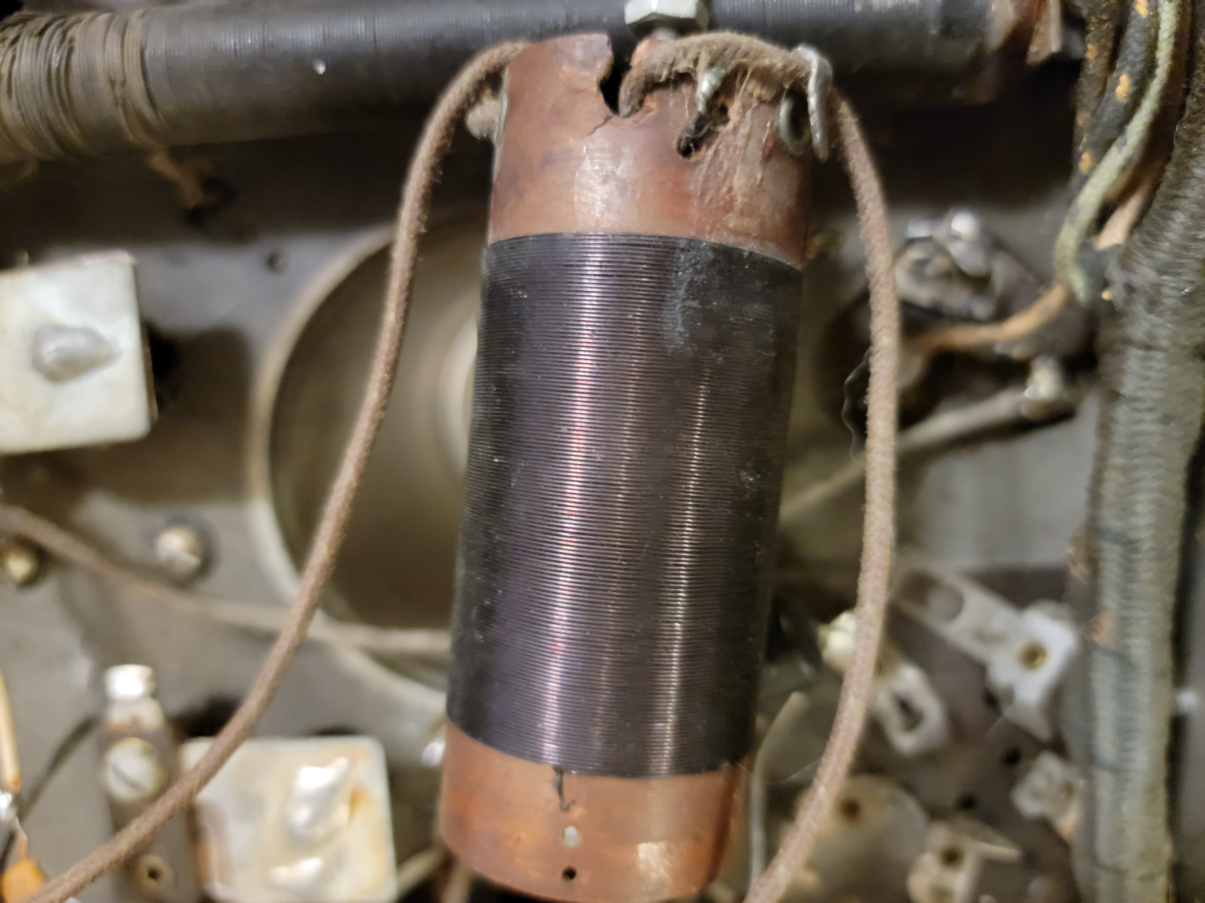
As well, the first appears to have had its secondary completely removed:

In that first pic you can see the bulk of the modifications that were done to it. My knowledge of old AM radios isn't the greatest...but from what I can see, it appears as if the first RF transformer has been turned into an inductor tied to one end of the first compensating condenser (along with the antenna connection) and ground. The cathode connection of the first RF tube has been disconnected.
Any idea what whoever worked on this last is trying to do? 
(This post was last modified: 01-13-2022, 11:52 AM by neil.)
Posts: 98
Threads: 34
Joined: Feb 2012
City: Philadelphia
State, Province, Country: PA
Two threads merged into one by admin.
Per Phorum rules, only one thread per subject radio allowed at a time.
https://philcoradio.com/phorum/showthread.php?tid=4586
Quote:II. Multiple threads on the same subject not allowed.
When you start a thread, please keep the discussion within the same thread.
Example: "Philco 90 broken"
After you've started that thread, please do not start another thread on "Philco 90 bad resistor" if it is the same Philco 90 being discussed in the original thread. Give others a chance to respond to your questions rather than asking them again in a new thread - please be patient.
These sort of threads will be immediately deleted, to keep clutter to a minimum.
Please cooperate with management in keeping one thread in the same place rather than scattering it around.
Posts: 7
Threads: 1
Joined: Jun 2021
City: London
State, Province, Country: ON
My apologies!!
So the modifications done to this set seem to be around removing the antenna transformer. Everything is the same, except the removal of R1 and R2, the primary(?) of the first RF transformer, and an additional small cap between the first and second compensating condensers. I'll try to get a scematic up with the modifications!
I would really like to have this set in full working order! I think I'll have to rewind the primary on that transformer 
So...what are my options? Does anyone here know what the correct number of turns is? Is there any way I could figure it out, without prior knowledge?
Users browsing this thread:
|
|
Recent Posts
|
|
Need to purchase some accessories for restoration of my Old Philco Radio
|
| Hi Paulo,
Welcome to the Philco Phorum.
I can see why you want to find good reproduction parts. That is a bea...MrFixr55 — 11:10 PM |
|
HiFi (Chifi) tube amp build - but my own design.
|
| Tim,
I have some bakelite sockets in my work shop that I can dig up. I believe quite a few are NOS. I will take photo...RodB — 10:03 PM |
|
Philco 610B oscillator wiring
|
| > The cathode as noted is wired directly to the ground side of the heater filament for that tube, not to the #17 and ...Radioroslyn — 08:12 PM |
|
HiFi (Chifi) tube amp build - but my own design.
|
| Tim;
I noticed your post a little late, but I would take one of the junk sockets and try to break a chunk out of it wi...Arran — 08:07 PM |
|
Need to purchase some accessories for restoration of my Old Philco Radio
|
| Here is a list of resources found in our online library that you might find useful. Mike's Gobs of Knobs email addres...klondike98 — 01:46 PM |
|
First Radio restoration
|
| Hi Tubeman,
Welcome to the Philco Phorum. Phamily Phriendly Pfun with Phine Pholks Phull of Philco Phacts. (See a p...MrFixr55 — 12:33 PM |
|
First Radio restoration
|
| You could post in the WANTED ADs section here on the Phorum and see if anyone has an RF generator that they want to sell...klondike98 — 11:55 AM |
|
Zenith H725
|
| Good ideas, thank you Arrange and Rich. I have the adhesive aluminum foil already and can try that immediately.
More ...EdHolland — 10:18 AM |
|
Graphics for majestic 1050 dial glass.
|
| Murf;
I found this thread on the ARF, the first photo has a pretty good view of the dial glass.
Regards
ArranArran — 01:12 AM |
|
Zenith H725
|
| hello Ed,
how about that speacial tape used for ducting it's like foil or how about thin piece of
aluminum roof flash...radiorich — 12:19 AM |
|
Who's Online
|
| There are currently no members online. |

|
 
|


![[-] [-]](https://philcoradio.com/phorum/images/bootbb/collapse.png)


