Posts: 13,776
Threads: 580
Joined: Sep 2005
City: Ferdinand
State, Province, Country: Indiana
Specifically, the subject radio here:
https://ronsradios.com/2021/07/14/philco...rs-part-1/
I have decided to use the bypass tricks discussed here to take care of the two audio interstage transformers, both of which have open primaries.
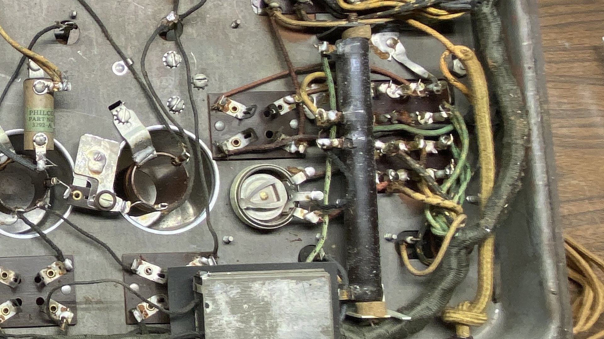
My question concerns the large three-section resistor, part (35).
Refer to the schematic here.
The resistor's sections are 3785, 157, and 640 ohms.
The 3785 ohm section is open.
A friend suggested that I scrape off the resistance wire of that section (only) and add a resistor across those terminals. However, the resistor is coated in ceramic, making that impossible.
Any suggestions? Since this is a cylindrical power resistor mounted by a screw and nut, it looks like this may be difficult to replace.
Thanks.
--
Ron Ramirez
Ferdinand IN
Posts: 5,164
Threads: 273
Joined: Nov 2012
City: Wilsonville
State, Province, Country: OR
You don't want to just put a resistor across the open section as you mentioned in your blog. So if you did not use one of those terminal lugs but instead fashioned a separate lug epoxied to the ceramic so that it has no chance for a potential reconnection of the open resistor you could put a new resistor across to the new lug. Just a thought...
Posts: 13,776
Threads: 580
Joined: Sep 2005
City: Ferdinand
State, Province, Country: Indiana
Hmmm. I'll look into it. Thanks.
--
Ron Ramirez
Ferdinand IN
Posts: 7,297
Threads: 268
Joined: Dec 2009
City: Roslyn Pa
There is a tip that I've heard of but haven't tried. The theory is that the nichrome wire oxidizes at point of contact on the solder lug. Chip away a small amount of the enamel to gain access the oxidized area. Clean up the connection. Not sure how you reconnect nichome wire short of crimping or spot welding. Use a bit of JB weld to replace the missing enamel and color to match.
About the same time the 87 came out the National Company out of Mass produce a receiver called a SW-3 which a similar problem. Have serviced several of them have used Ohmite Divide ohm resistors. They have a side that the nichrome is exposed and slider that can be adjusted from from one end to the other. If more taps are needed add more sliders.
When my pals were reading comic books
I was down in the basement in my dad's
workshop. Perusing his Sam's Photofoacts
Vol 1-50 admiring the old set and trying to
figure out what all those squiggly meant.
Circa 1966
Now I think I've got!
Terry
Posts: 2,118
Threads: 112
Joined: Jun 2010
City: Medford OR (OR what?)
I have always thought it to be a combination of corrosion and mechanical movement. The nichrome can get super hot. Expansion rate is 14.0E6 + or - %10 (so says google) but the contact point with the tinned copper terminal, while being a heat sink, is probably going to have some ware/ expansion in that contact area. A crimp with some plyers SOMETIMES fixes it.
"I just might turn into smoke, but I feel fine"
http://www.russoldradios.com/
(This post was last modified: 07-20-2021, 07:32 PM by Phlogiston.)
Posts: 13,776
Threads: 580
Joined: Sep 2005
City: Ferdinand
State, Province, Country: Indiana
I appreciate the responses. Thanks.
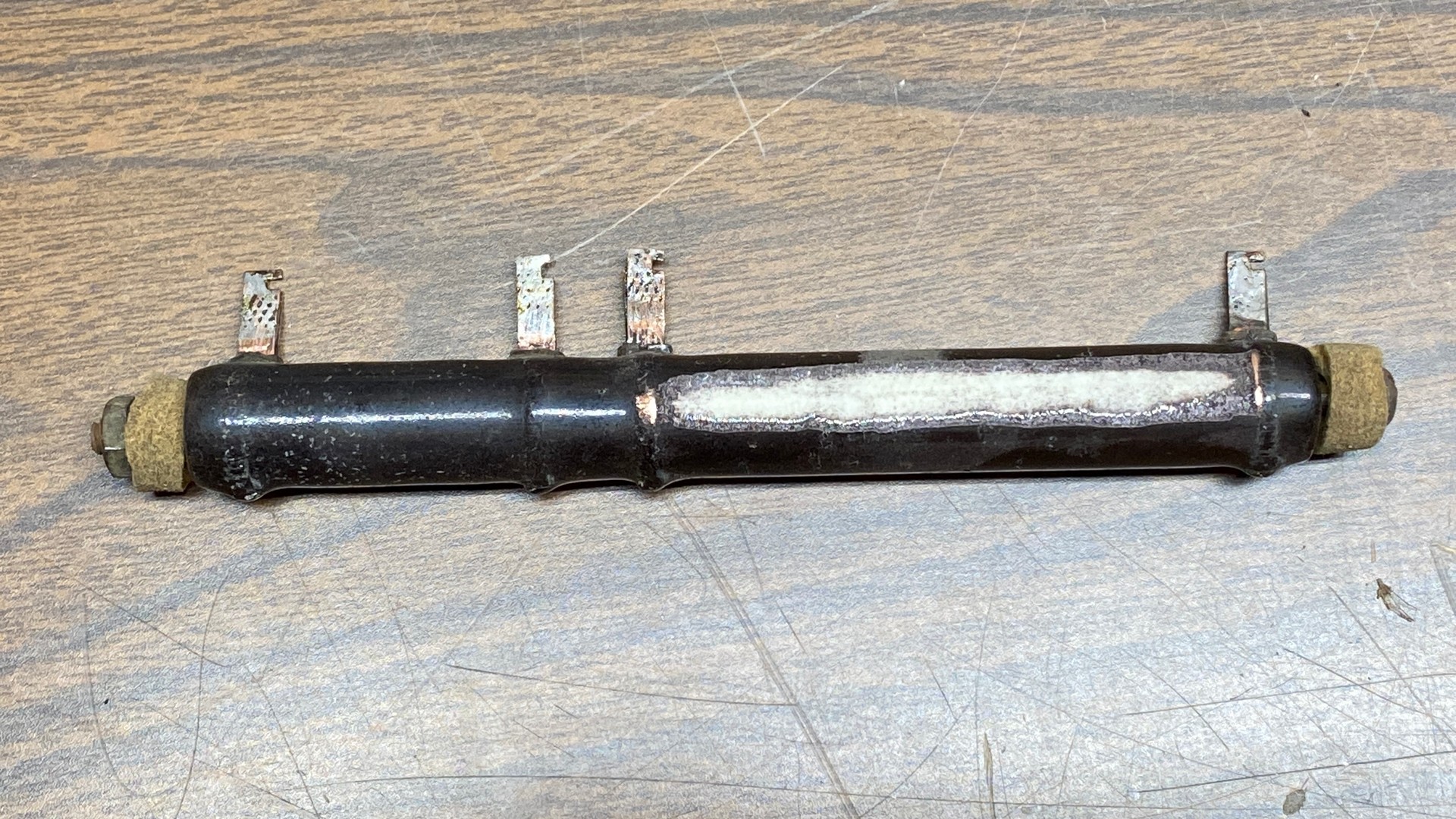
Here is the resistor in question.

I tried the crimp with pliers - no joy.
I then decided to do something else.
I'll be posting this on my blog in the near future, but you can see it right now.

Using my Ryobi "Dremel" tool - the best $5 I have ever spent, and yes, I bought it new on closeout, about 25 years ago - I ground through the outer coating and removed part of the resistance wire as shown. This way, I will be able to connect a new resistor (or resistors) to the original terminals, without worry of the original resistance suddenly becoming "active" again.
(H/T to Ed Locker for the idea.)
I will likely coat the ground-off area with J-B Weld before reinstallation. And, in case you were wondering, I did the grinding on the bottom side, where it will not be seen once reinstalled in the radio.
Ok. If you have followed this post thus far, I now have another question for you.
Given that Mouser Electronics has suitable power resistors in 3600 ohm and 180 ohm (which would add up to 3780 ohms, very close to the original 3785 ohms) and in 3900 ohms -
Would you replace the 3785 ohm section with a 3900 ohm resistor or with two resistors, 3600 ohms and 180 ohms?
I think I already know the answer, but I would like to know your thoughts/opinions.
Thanks in advance for your comments.
--
Ron Ramirez
Ferdinand IN
Posts: 2,118
Threads: 112
Joined: Jun 2010
City: Medford OR (OR what?)
I wonder if you could actually put 10W resistors inside of that sucker. The mounting bolt would have to move/change. Then drill holes out to the terminals.
My thoughts previously, were more inline with candohm construction. I would think that these would be subject to less corrosion.
"I just might turn into smoke, but I feel fine"
http://www.russoldradios.com/
Posts: 1,409
Threads: 72
Joined: Oct 2007
City: Linn Creek, MO
Ron, I think I would go with the 3900 ohm, it would be within 5 percent of the original.
Steve
M R Radios C M Tubes
Posts: 13,776
Threads: 580
Joined: Sep 2005
City: Ferdinand
State, Province, Country: Indiana
Thanks Steve. I'm going with 3900 ohms. Resistors (this 3.9K plus a 68K, 1 watt to replace the 70K resistor) have been ordered from Mouser.
Russ, the only problem with putting resistors inside the ceramic tube is that then you lose the ability to attach it to its mounting brackets. It depends upon a very long screw, with bolt, to hold it in place.
--
Ron Ramirez
Ferdinand IN
Posts: 13,776
Threads: 580
Joined: Sep 2005
City: Ferdinand
State, Province, Country: Indiana
Well, crap. All this work only to find out the power transformer is bad - partial short in one half of the HV winding.
I've posted a "Wanted" ad on this subject.
--
Ron Ramirez
Ferdinand IN
Posts: 44
Threads: 5
Joined: Jan 2012
City: Concord, NC
Since I just went through a Model 65, just curious about what you intend to do about the cap and resistor combos like the 3292a in the photo. I would imagine that those could be restuffed?
I saved the ones from the 65 that I had to replace just in case...
Richard
Posts: 1,106
Threads: 88
Joined: Jun 2011
City: Tacoma
State, Province, Country: Washington
Those are super simple to restuff. I have a book that lists every internal layout of those block caps. All you have to do is cut the wires where they loop around the solder lugs, then heat the block up a bit to loosen the grip between the tar and the sides of the block, take a small screwdriver or a brad or paper clip or some such and just push the insides out. Install your replacement cap(s) and/or resistor and there you have it. I repot mine with paraffin wax, but you don't even have to do that.
Posts: 13,776
Threads: 580
Joined: Sep 2005
City: Ferdinand
State, Province, Country: Indiana
RGallahue
Brenda has already answered your question, but I also addressed that issue here:
https://ronsradios.com/2021/07/19/philco...rs-part-2/
As Brenda said, they are super simple to restuff.
--
Ron Ramirez
Ferdinand IN
Users browsing this thread:
|
|
Recent Posts
|
|
Need Help to ID this radio 11 tube Philco
|
| Yes the 16B as morzh pointed out. Specifically its the January 1935 model version of the 16B. There are a couple earli...klondike98 — 11:51 PM |
|
48-482 rear panel help
|
| Welcome to the Phorum, keithchip! How far you take a radio on cabinet restoration is a matter of personal preference. ...GarySP — 11:28 PM |
|
48-482 rear panel help
|
| I've recently finished the internal restoration of a locally purchased Philco 48-482. The cabinet is in ok shape except ...keithchip — 10:28 PM |
|
Need Help to ID this radio 11 tube Philco
|
| Welcome to the Phorum, Ken! Lots of help here for all of your restoration questions. Take care and BE HEALTHY! - Gar...GarySP — 07:59 PM |
|
Need Help to ID this radio 11 tube Philco
|
| Thank you.
I went to your online library and found 2 schematics.
I will download and compare to components!Ken D. — 06:31 PM |
|
Need Help to ID this radio 11 tube Philco
|
| It is a 16B tombstone.morzh — 06:13 PM |
|
Zenith H725
|
| David - sorry, I reread your post and finally saw THD - now the % figures make sense. Thanks for explaining.
The PSU...EdHolland — 06:06 PM |
|
Need Help to ID this radio 11 tube Philco
|
| Hi Everyone,
New member but have been reading this for awhile for tips!
Vaccum tubes were before my time so bear with ...Ken D. — 06:03 PM |
|
My Philco 37-116 Restore
|
| Thank you MrFixR55, I appreciate your comments very much. I do not detect much hum if any so I will be staying with the ...dconant — 05:15 PM |
|
My Philco 37-116 Restore
|
| Hi DConant
Yes, you can replace chokes with resistors. You do stand the risk of increased hum. the solution is to inc...MrFixr55 — 04:23 PM |
|
Who's Online
|
| There are currently no members online. |

|
 
|


![[-] [-]](https://philcoradio.com/phorum/images/bootbb/collapse.png)


