Posts: 13,776
Threads: 580
Joined: Sep 2005
City: Ferdinand
State, Province, Country: Indiana
RGallahue
I was thinking about your last post so I looked at some of my photos.
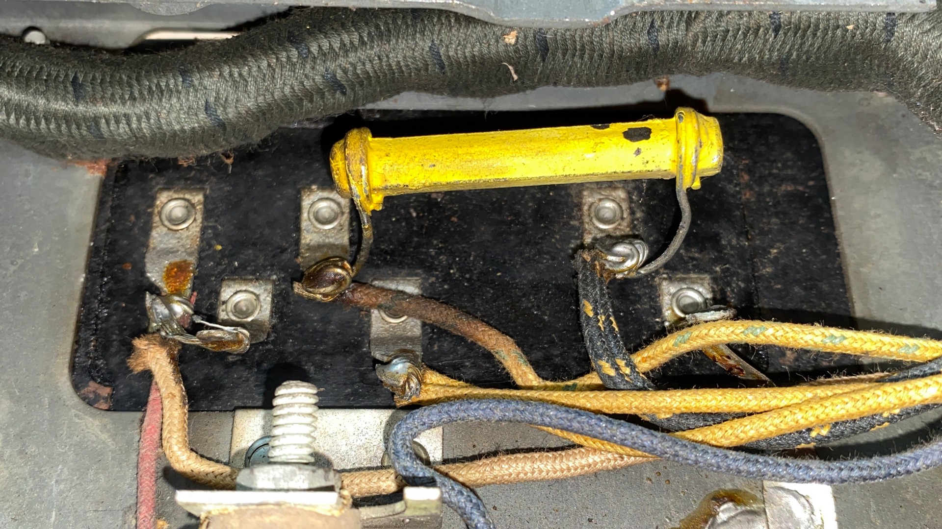
There is a tan wire in my 65 which connects to terminals 1 and 2 of the filter condenser block, goes into the wiring harness, and comes back out near filter choke (21) where it connects to one terminal of the choke.
See photo below.

--
Ron Ramirez
Ferdinand IN
Posts: 44
Threads: 5
Joined: Jan 2012
City: Concord, NC
Thanks! That was the one that I replaced when I wired the number 1 terminal back into the system. The original tan wire as well as the connection to the 80 was moved to terminal 2, and I left them there and completed the circuit by wiring #1 to the filter choke, so my 65 is now wired in accordance with the schematic if not in agreement with the original construction. The only item I did not do was a jumper between terminals #1 and #2, but that circuit is now completed in any case.
Good luck with the garage sale.
Thinking about those oscillations...Could this be emanating in the detector circuit in some form or fashion? If the shields around the 24s are "holding" and the bypass capacitors are well grounded (as I would expect them to be, given they way they are mounted to the chassis) this does not make any sense. I see that you replaced the volume control so I would not expect issues there. My #15 was good so I did not mess with it, but I do wonder about the 27. I see that you swapped that out though, apparently with no effect. I presume that the cathode resistor is within tolerance and the cathode bypass cap was apparently replaced (restuffed) as well...
Anyone else out there have ideas, thoughts or suggestions?
Richard
(This post was last modified: 08-11-2021, 12:21 PM by
RGallahue.)
Posts: 2,118
Threads: 112
Joined: Jun 2010
City: Medford OR (OR what?)
Hay, I was wondering if your B+ to the first 2 224s was dropping noticeably AS the unit goes into oscillation (test point "D"). Also checking values in parts 6 and 10 (must be assemblies or blocks).
"I just might turn into smoke, but I feel fine"
http://www.russoldradios.com/
Posts: 13,776
Threads: 580
Joined: Sep 2005
City: Ferdinand
State, Province, Country: Indiana
Thanks Russ,
We're having a yard sale here starting tomorrow morning so I cannot check right away. I will pull the 65 back out and check B+ next week.
--
Ron Ramirez
Ferdinand IN
Posts: 13,776
Threads: 580
Joined: Sep 2005
City: Ferdinand
State, Province, Country: Indiana
So I finally checked voltages in my 65; everything looks ok to me. No anomalies noted in B+ voltage when the radio goes into oscillation. I even tried adding extra capacity across a few different bypass capacitors, no joy.
Oh, and the only capacitors which were not changed were two micas. All the tubular caps with resistance wire were restuffed with new capacitors and new resistors. All individual resistors...what few there are..were also replaced with new resistors.
--
Ron Ramirez
Ferdinand IN
Posts: 44
Threads: 5
Joined: Jan 2012
City: Concord, NC
Well, the only other difference between yours and mine is the capacitive coupling across the interstage transformer primary. Looks like all other possibilities are exhausted. I know you are trying to maintain originality but it would be interesting to splice a replacement transformer across there and see if that resolves the issue.
Also, thanks for the link to your blog. Going to pay more attention to that in the future as I could have used a few of those pointers when I was rebuilding mine!
For a replacement of the interstage transformer I used a Hammond 124a which does a fine job driving the output tubes. It is also small enough that it might either fit inside the case or you might be able to bury it topside within the old transformer housing reconstructed around it.
Good luck!
Richard
Posts: 13,776
Threads: 580
Joined: Sep 2005
City: Ferdinand
State, Province, Country: Indiana
Richard - Thanks. I have decided not to go any further with my 65. I'm not going to be using it every day, after all. It works and that is good enough.
I honestly do not feel that changing the audio interstage section from resistance coupling back to transformer coupling will make a difference other than possibly slightly louder audio. Changing the volume control in Model 65 varies the screen voltages of the two 24 RF tubes. This would have nothing to do with the audio section of the radio. If I were to change back to transformer coupling, however, I would purchase the P-T156 transformer from Antique Electronic Supply since it costs half as much as the Hammond.
I am, however, going to make an investment to make one of my F-10 speakers work again. I have managed to get the field coil out of the "pot" of one of the speakers and it will be going to Alabama for a rewind soon.
--
Ron Ramirez
Ferdinand IN


![[-] [-]](https://philcoradio.com/phorum/images/bootbb/collapse.png)


