Posts: 14
Threads: 5
Joined: Mar 2021
City: Bakersfield
State, Province, Country: Ca
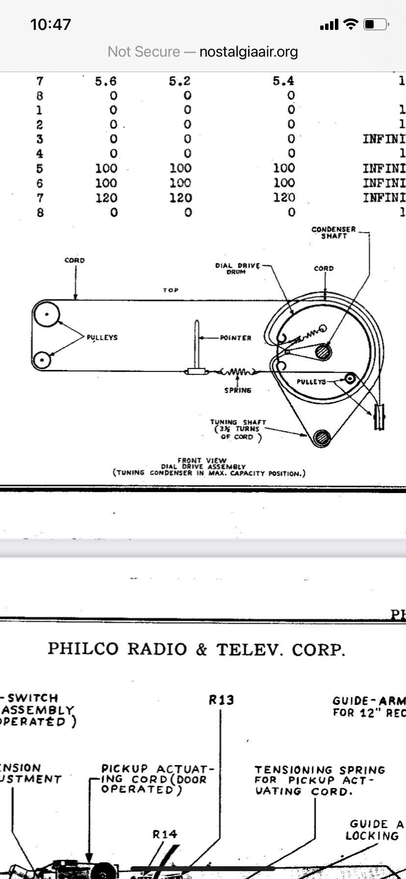
Hello. I am working on a bing crosby and am having trouble with the dial cord. The existing cord is with the radio, but the dial pointer cord had come off the wheels. I found a diagram and reinstalled the cord per the diagram, but the pointer is moving in the opposite direction from the tubing gang. For the life of me I don’t see how it is possible for this setup to work. The low end on the dial is on the least when looking at the radio. The variable capacitor tuner becomes fully closed by turning it counter clockwise. The pointer dial cord comes off the top of the tuning gang which moves the pointer/cord towards the upper end of the dial when the condenser is moving towards the closed position. What am I missing?

Posts: 1,125
Threads: 44
Joined: Feb 2015
City: Roseville, MN
Pay attention to how the cord wraps around the tuning shaft; clockwise or counterclockwise.
Posts: 14
Threads: 5
Joined: Mar 2021
City: Bakersfield
State, Province, Country: Ca
I’m sure I have the cord installed the same as the diagram. The pointer rides on the bottom of the scale witch is the only way it will fit. The cord for the pointer comes off the top of the top of the drive wheel and goes to the left along the top to the first pulley.
With this setup a counter clockwise turn of the tuning knob moves the pointer to the right towards the top of the AM band. The large drive wheel is attached directly to the tuning condenser. The tuning condenser is tuning stations (455 fully closed, counter clockwise, and 1600 fully open clockwise), but for this setup to move the pointer to work it would have to be opposite. Is it possible the tuning condenser is backwards in its operation?
Posts: 14
Threads: 5
Joined: Mar 2021
City: Bakersfield
State, Province, Country: Ca
Sorry for the stupid post? I have the chassis on the bench and not in the cabinet. I just realized the chassis is mounted upside down in the cabinet. Duh.
Posts: 1,125
Threads: 44
Joined: Feb 2015
City: Roseville, MN
Bet you're not the first! Those development engineers' ghosts are getting another big laugh.
Posts: 5,163
Threads: 273
Joined: Nov 2012
City: Wilsonville
State, Province, Country: OR
We've all done something like that at one point or another!


![[-] [-]](https://philcoradio.com/phorum/images/bootbb/collapse.png)


