Posts: 2
Threads: 1
Joined: Sep 2021
City: Kansas City
State, Province, Country: MO
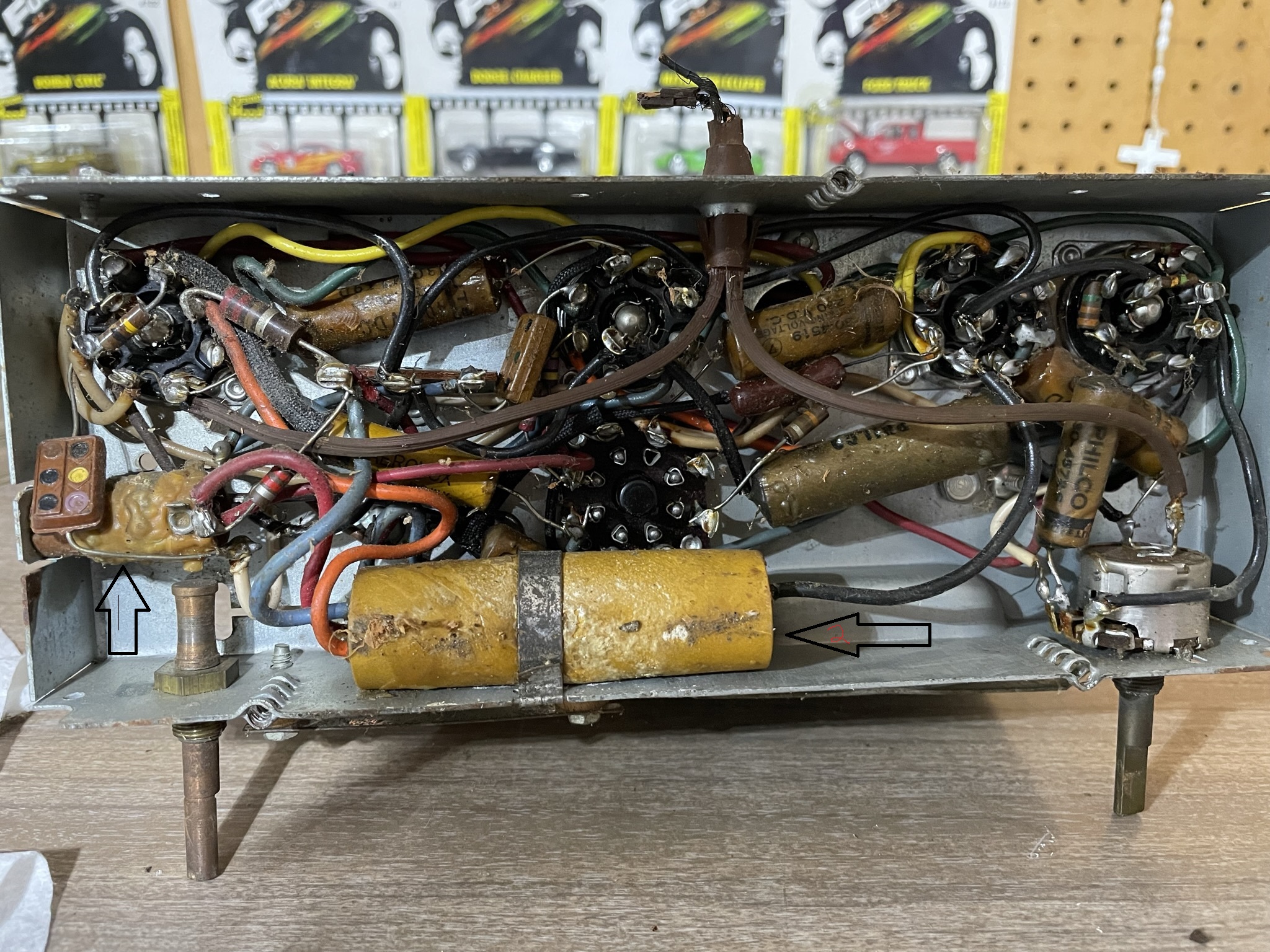
Just picked up a Philco 48-200 Ivory and this is my first try at radio restoration.
Couple questions:
Can anyone tell me what this wax-covered thing is at 1?
When it comes to 3 section filters (Number 2). I assume I replace it with 3 separate caps? How do I know which wire to use for which cap? The schematic shows:
Condensor Electrolytic 30mf
Condensor Electrolytic 25mf
Condensor Electrolytic 20mf
Any idea what voltages to use? I'm

not that great with reading schematics yet.
Thanks!
Posts: 120
Threads: 15
Joined: Aug 2017
City: Fort Worth
State, Province, Country: TX
The item you have marked as 1 is T400, the oscillator transformer. See left side of parts layout in Troubleshooting for Section 4. I would replace the 3-section electrolytic with three separate ones. The voltages and color code for the electrolytics are probably marked on your item 2. You need to unclamp it from the chassis and see if it will rotate far enough to see if anything is printed on the side you can't see. If there are no markings, I would use 450 vdc replacements. You would then also have to trace the wiring from each cap to see which wires connect to pin 7 of the 35Y4 tube and resistors R101 and R102 as shown in section 1 of the schematic.
Posts: 2
Threads: 1
Joined: Sep 2021
City: Kansas City
State, Province, Country: MO
Thank You!
Do I need to do anything with the T400, the oscillator transformer?
Posts: 120
Threads: 15
Joined: Aug 2017
City: Fort Worth
State, Province, Country: TX
Probably not. If the tubes are ok and you do the other standard replacements of old electrolytics, old paper/wax caps, and out of tolerance resistors and the radio works after that, then the oscillator transformer is working. If you wanted, you could check the resistance readings between pins 1 and 4 - should be approx 7 ohms and between pins 2 and 3 - should be approx 2.6 ohms (see middle and lower portions of Section 4 schematic page for T400 details).
 not that great with reading schematics yet.


![[-] [-]](https://philcoradio.com/phorum/images/bootbb/collapse.png)


