Posts: 337
Threads: 13
Joined: Apr 2019
City: Greenwood
State, Province, Country: Delaware
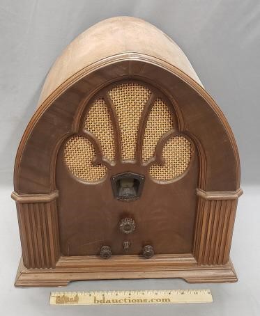
I've been following Bob Andersons trials and tribulations on his 90, but this one in pretty good shape overall. Like his, this has a single 47 output tube.
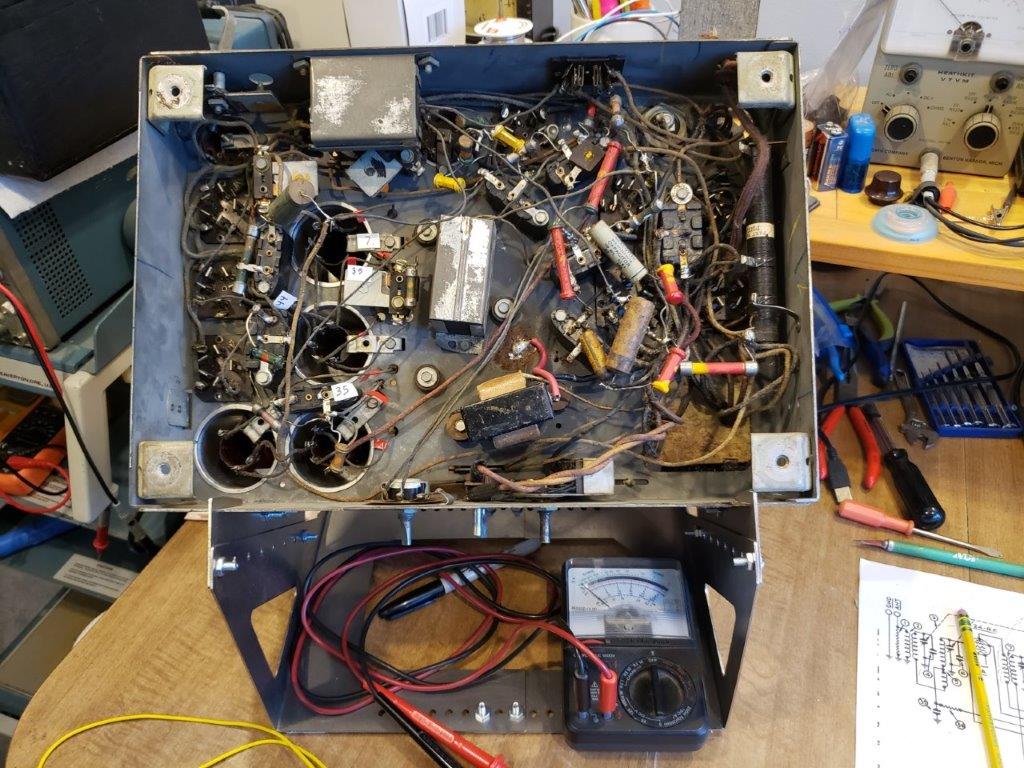
What's missing:
-the Large tube shield (with tube layout sticker)
-another shield on the other side (there's a clip there)
-one of the original filter capacitors
-no stickers!
Other:
-strange shape of the volume control shaft, makes the knob wobble. Don't want no wobbling knobs!
-strange red grounding wire on the choke housing to the chassis
-deformed tuning dial
Tubes all test good (2 may be original). I use an old Signal Corps I-177 tester.
The tubes all light up with the rectifier removed.
Transformers, including PT, speaker, output transformer, and choke all seem to be good except for the RF 1st Det. coil (7), open primary. What a surprise.
BTW, I've found that a dab of WD-40 on the grid caps and tube pin sockets make them suckers jump right out of there! I use a q-tip. Also grip tubes by the base, not the envelope.
And, now for your viewing pleasure:
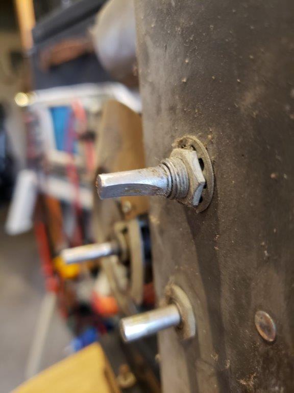
Notice the shape of the volume control shaft
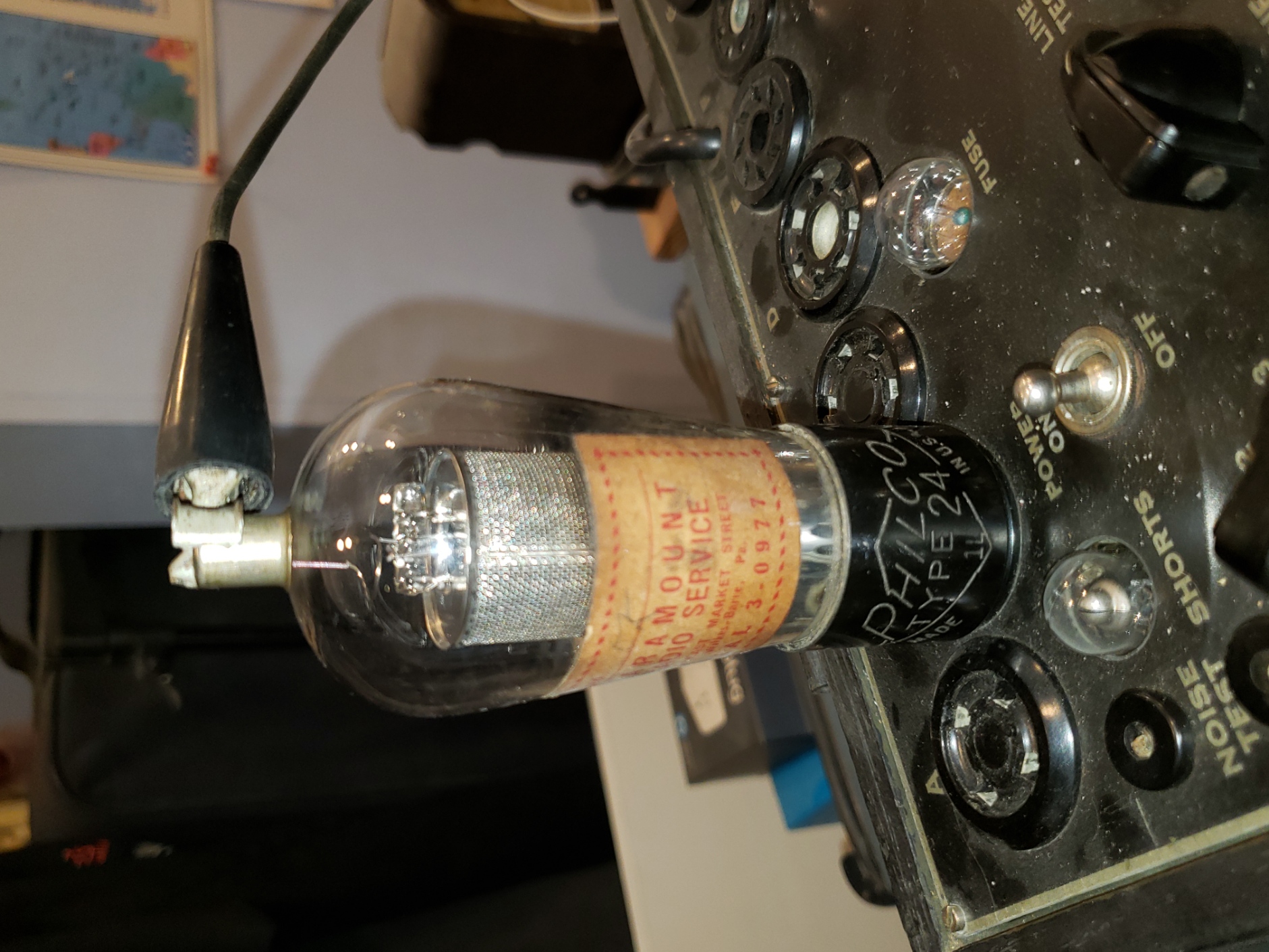
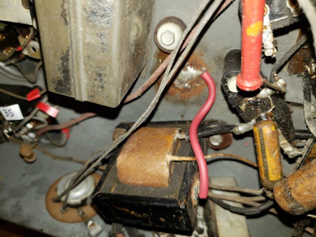
Big red ugly wire grounding the case which is insulated from the chassis (?!)
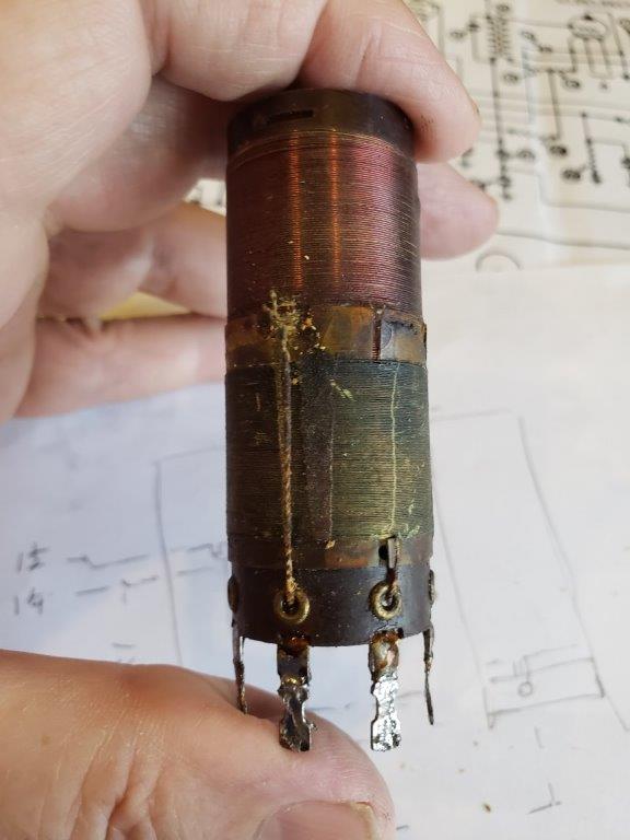
All that green stuff is fragmented wire.
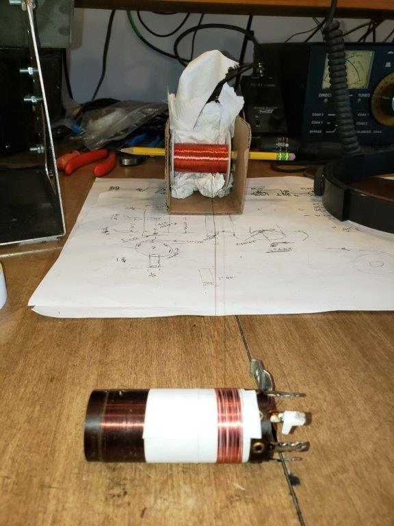
91 turns required (don't laugh at my winder! it works) That's 3m electrical tape sticky side out, one layer.
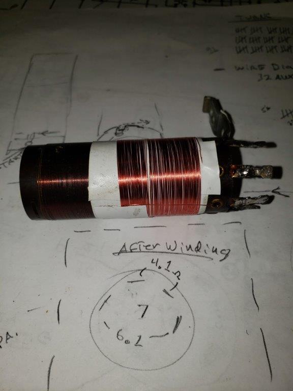
That's all folks (until round 2)
Posts: 811
Threads: 43
Joined: Dec 2008
City: Chicago, IL
Regarding the filter choke. It looks like there are phenolic insulating washers on the mounting screws. Mine is metal on metal. I'm thinking they might have been trying to reduce hum by making a single, solid grounding point ?
Also I suspect that is a replacement volume control. You could try building it up with some solder or JB Weld.
(This post was last modified: 11-17-2021, 10:26 PM by Bob Andersen.)
Posts: 337
Threads: 13
Joined: Apr 2019
City: Greenwood
State, Province, Country: Delaware
Thanks Bob- i will try to solder a shim on the shaft- and remove the ugly red thing and put choke back like its supposed to be.
I'm thinking of putting the tubes back in before I replace caps and resistors to see if it's alive. I would bring it up slowly and monitor AC voltage and current, as well as B+. There's a spider web of replacement capacitors and lifted resistors floating in mid-air.
Or is that not a good idea?
-Simon
Posts: 811
Threads: 43
Joined: Dec 2008
City: Chicago, IL
I suggest you did what I did with mine.
1. Disconnect or replace the AC line filter caps. They are in circuit even with the radio turned off and have a nasty habit of popping.
2. Put all the tubes in except the 80 rectifier and power it up. No need to do it slowly, just go for 117 VAC. All the tubes and dial lamp should light up. You can check the power transformer secondary by stick your AC voltmeter probes into the 80 tube socket. 5 volts across the fat pins. Something like 500-700 across the smaller pins.
3. Replace the two electrolytic caps and apply full power using a dim bulb or similar current limiting device.
I don't really see the point of slowly powering it up unless you're trying to reform the old electrolytics.
Posts: 337
Threads: 13
Joined: Apr 2019
City: Greenwood
State, Province, Country: Delaware
Already did the no-rect-tube-PT-voltage-check, all ok. Didn't think about AC line filter caps, anyway they didn't 'pop'.
OK on the electrolytics, I will check them out next, then see if it's alive-
Thanks 
Simon
Posts: 1,840
Threads: 117
Joined: May 2008
City: Omak
State, Province, Country: WA
Hello Simon,
Well I may have a Volume control in my stash of Controls but I will not be able to check that stash till winter break .
Sincerely Richard
Posts: 337
Threads: 13
Joined: Apr 2019
City: Greenwood
State, Province, Country: Delaware
Thank you Richard, that is good of you.
Posts: 337
Threads: 13
Joined: Apr 2019
City: Greenwood
State, Province, Country: Delaware
It's looking like the 3,500 ohm segment of the large tubular power resistor is bad. It's measuring 70K building up to 90K with a digital VOM. I tried resoldering the ends, but that stuff they use is flimsy cloth covered stuff and just came apart.
Question is, what watt 3.5K resistor will work?
-Simon
Posts: 16,483
Threads: 573
Joined: Oct 2011
City: Jackson
State, Province, Country: NJ
Simon
What section on the sch is the 3500 Ohms?
People who do not drink, do not smoke, do not eat red meat will one day feel really stupid lying there and dying from nothing.
Posts: 337
Threads: 13
Joined: Apr 2019
City: Greenwood
State, Province, Country: Delaware
Bottom right 58 between 3 and 4 Mike
Posts: 51
Threads: 3
Joined: Nov 2021
City: Drexel Hill
State, Province, Country: PA
Hi Simon...I'm new to the forum and vintage radio restoration in general. Having a problem with the same resistor...only 1750 ohms from end to end. 200 ohms from terminal 1 to 2...1750 from 1 to 3 and 1750 end to end. Resistor starts to burn up at terminal one on power up. Popped the electrolytic connected to it last night.
Posts: 337
Threads: 13
Joined: Apr 2019
City: Greenwood
State, Province, Country: Delaware
Hi cnob, I was tempted to fire this thing up but now glad I didn't. I'm going to trace out all the circuits first because the wiring is a mess. BTW, the 2 filter capacitors 56 and 57 should be 6 uf
Posts: 51
Threads: 3
Joined: Nov 2021
City: Drexel Hill
State, Province, Country: PA
Posts: 337
Threads: 13
Joined: Apr 2019
City: Greenwood
State, Province, Country: Delaware
Update on the Tubular Resister 58 - now it's working!
I unsoldered the lead going to F.C. socket (terminal 4) to isolate that part of the resistor, and must have reflowed the solder, because it then measured about 3.6K. Soldered back the lead and measured 3.4K or so. I think condenser 24 is having some weird effect on it.
-Simon
Posts: 16,483
Threads: 573
Joined: Oct 2011
City: Jackson
State, Province, Country: NJ
SImon
I am not sure, but I think it dissipates 5.7W. So you need 10W rated resistor to sub it.
People who do not drink, do not smoke, do not eat red meat will one day feel really stupid lying there and dying from nothing.
Users browsing this thread: 1 Guest(s)
|
|
Recent Posts
|
|
Need Help to ID this radio 11 tube Philco
|
| It is a 16B tombstone.morzh — 06:13 PM |
|
Zenith H725
|
| David - sorry, I reread your post and finally saw THD - now the % figures make sense. Thanks for explaining.
The PSU...EdHolland — 06:06 PM |
|
Need Help to ID this radio 11 tube Philco
|
| Hi Everyone,
New member but have been reading this for awhile for tips!
Vaccum tubes were before my time so bear with ...Ken D. — 06:03 PM |
|
My Philco 37-116 Restore
|
| Thank you MrFixR55, I appreciate your comments very much. I do not detect much hum if any so I will be staying with the ...dconant — 05:15 PM |
|
My Philco 37-116 Restore
|
| Hi DConant
Yes, you can replace chokes with resistors. You do stand the risk of increased hum. the solution is to inc...MrFixr55 — 04:23 PM |
|
Zenith H725
|
| 1.7-3.9 %, a modified Sine wave inverter is around 25%. Most generators from big box stores run 10% at a 50% load. What ...David — 04:06 PM |
|
My Philco 37-116 Restore
|
| I am having a heck of a time doing the alignment on the AM band. I can't seem to dial in the 1500 KC oscillator. I can h...dconant — 03:35 PM |
|
Zenith H725
|
| David - I think I understand but what units are you discussing (Low of 1.7, high of 3.9)?
Budget constraints for Ham ...EdHolland — 01:43 PM |
|
My Philco 37-116 Restore
|
| You're doing great.
I wish I could be more involved, but my mind is right now preoccupied with the reason I am here in ...morzh — 12:21 PM |
|
My Philco 37-116 Restore
|
| Hope you guys are still with me.
I have moved on to the alignment. I completed the IF alignment which was pretty muc...dconant — 10:47 AM |
|
Who's Online
|
There are currently 733 online users. [Complete List]
» 1 Member(s) | 732 Guest(s)
|
|
|

|
 
|


![[-] [-]](https://philcoradio.com/phorum/images/bootbb/collapse.png)


