Starting a 37-10 project - odd cap question
Posts: 12
Threads: 1
Joined: Oct 2021
City: Bluemont
State, Province, Country: VA
Greetings all!
I have recently inherited an unfairly treated 37-10 that I would like to get started with the usual safety checks and parts replacement. This radio has been in the family continuously since my great-grandfather purchased it, and I'd really like to have it put back into working order.
I've pulled the chassis, given it a bit of a dust blow-out, and in preparation for ordering parts, I've also downloaded a mess of documents on it.
There is a cap in the "power unit" section that I cannot find referenced in the schematics, parts list, or drawings of the chassis. I thought maybe I'd been mistaken on the model information, but the sticker inside the cabinet, along with some quick cross-checking of other pieces/parts show up as being legitimately in the correct place and part numbers, etc, so I'm feeling confident that this is at least probably likely correctly identified.
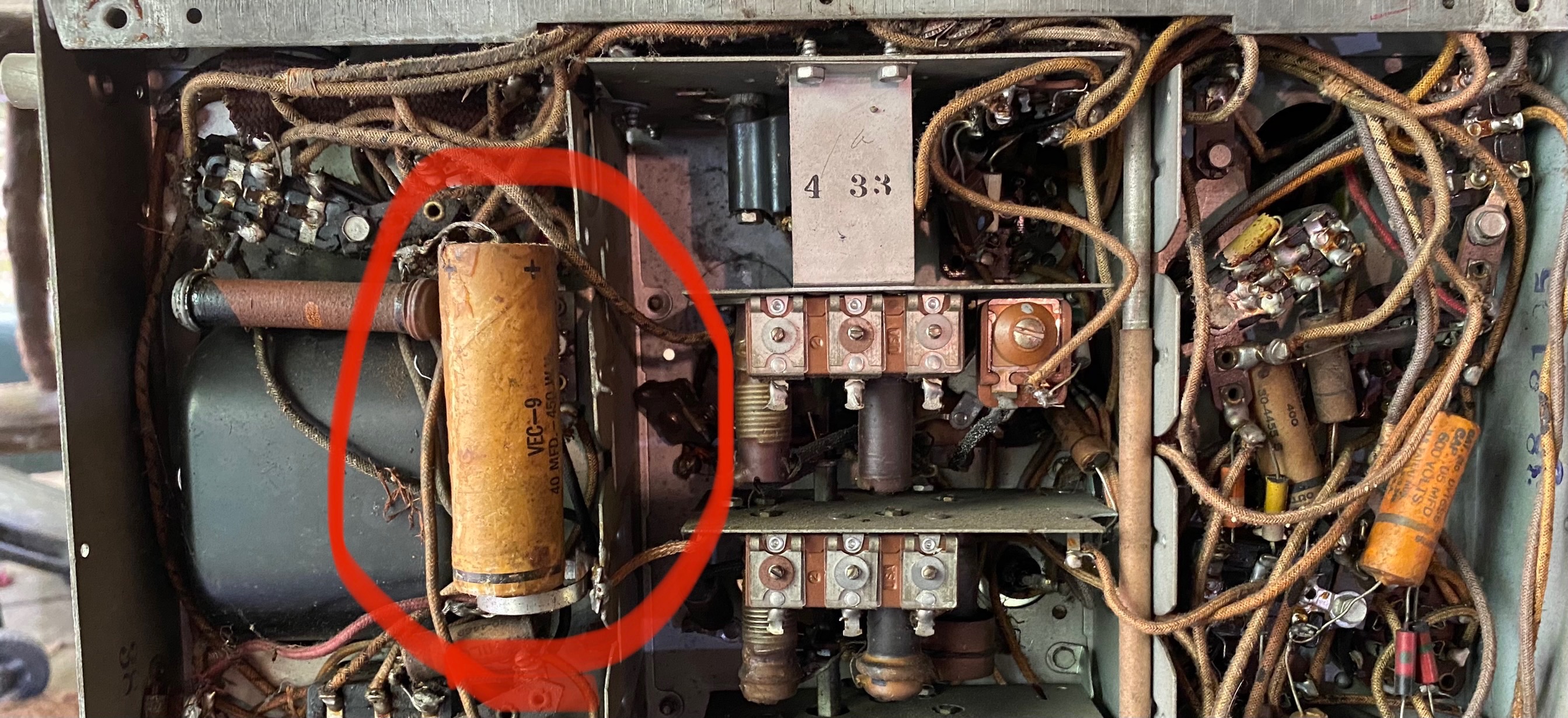
I've pulled the cap slightly out of the retaining mount so that I could get a better look at it.
It's appears to be labeled 40uf/450V. If you can zoom in, you'll see the markings on the right side. I can provide a closer image if that helps.

There's no part in the part list with that spec.
The drawing of the underside of the chassis just has nothing there.... The other parts in the immediate are I've been able to find and identify. So, it seems I have an extra part?
I'm not quite ready to yank it all the way out to see if there is a part number underneath and I'm just not reading the markings correctly, or follow those wires to see where it's hooked up and maybe back-trace the schematic, but that might be my next step.
I searched the forum, but couldn't find anyone else that seems to have mentioned this. I did, however, find reference to an updated service bulletin "Changes: July 1937"-- and while it mentions this model, it had nothing to do with this capacitor.
Can anyone shed light on it? I mean, I intend to replace the cap anyway, but if this rings a bell, and might point me toward new and better reference materials, I surely would prefer to avoid any additional surprises as I start fiddling with this thing. Or if it legitimately shouldn't even be there, I'd like instead to put it all back to the way it should be.
Thanks in advance for any help!
Knows enough to be dangerous, occasionally successful, rarely correct.
Posts: 120
Threads: 15
Joined: Aug 2017
City: Fort Worth
State, Province, Country: TX
Welcome to the Phorum! I think the part is a long ago replacement electrolytic cap. The schematic for the radio calls out four electrolytic caps - 16 mfd (item 31), 8 mfd (item 82), and 10 mfd and mfd 20 (item 84). The 10 and 20 mfd ones appear to be in one can and the other two in separate cans. These cylindrical cans should be standing vertically on top of the chassis. They will be marked on the side with their values. That info may be obscured by other items. My guess is someone had reason to replace one electrolytic cap and added the 47 mfd cap under the chassis. It might have been the 20 mfd cap since its in the same can as the 10 mfd cap. Using a higher value of 47 is not unheard of either. Tracing the wiring in the schematic should tell you which cap it replaced. This is not an easy radio to work on. It seems crowded under the chassis and I saw two bakelite blocks which have caps inside, potted with a tar like substance. On the plus side, there is a lot of documentation.
(This post was last modified: 10-04-2021, 08:14 PM by LarryFS.)
Posts: 7,296
Threads: 268
Joined: Dec 2009
City: Roslyn Pa
Yank it. Someone wanted to disguise a fix for problem that they couldn't find or fix.
When my pals were reading comic books
I was down in the basement in my dad's
workshop. Perusing his Sam's Photofoacts
Vol 1-50 admiring the old set and trying to
figure out what all those squiggly meant.
Circa 1966
Now I think I've got!
Terry
Posts: 12
Threads: 1
Joined: Oct 2021
City: Bluemont
State, Province, Country: VA
Thank you both, Larry and Terry.
I had considered that it was "a fix" of some sort. It has clearly been serviced to one degree or another in the past.
A couple of the tubes are, while the correct type, no longer "Philco" branded. The power cord is most certainly not original(and a bit of a sloppy soldering job). And I noted that there is also a resistor in the RF unit that is... well, the lead appears to have been actually snipped vs just "come loose" or unsoldered. So... somebody has had their hands in here at some point. I won't comment on other also noted "globby" soldering joints beyond that they exist.
There may have been a small number of quietly expelled vulgarities, an obscenity or two, and a dash of profanity for good spice.
Now that said, if someone had gone in here and added this 40mfd as a "fix" vs replacing the canned 10/20 combo, two things makes me go "hmmm" that I would like to possibly also get an opinion on. If you have the time, of course.
- doesn't this notably change the characteristics of the rectifier output?
- if someone had just added this in there, whether as a replacement for one leg of the canned combo or just a "I have no clue but it works now" type of "fix", I find it curious that they would go through the trouble of attaching a mounting bracket to the chassis. That seems like more work than just replacing the original part or just hooking it up and calling it a day, no?
I'll double-check it later this afternoon after work and see where it hooks up.
thank you again for your replies.
Knows enough to be dangerous, occasionally successful, rarely correct.
Posts: 12
Threads: 1
Joined: Oct 2021
City: Bluemont
State, Province, Country: VA
I am not entirely certain of this, of course, since it would have happened even before my father was born.
But I'm reasonably, and probably more emotionally, convinced that Great-Granddad took this to Emmett's Fix-it-Shop.
And Emmett also, like myself, knew enough to be dangerous.
::sigh::
Taking careful notes and yanking weird parts and wires that.... go nowhere but to weird parts.

Knows enough to be dangerous, occasionally successful, rarely correct.
Posts: 120
Threads: 15
Joined: Aug 2017
City: Fort Worth
State, Province, Country: TX
I have come across added electrolytic caps. The best option is to make it like the schematic. That means tracing the wiring from the original caps to see if the added cap replaced one of the original ones. If it didn't, make notes/photos of what is connected to what when you remove it. Replace the old electrolytics with new ones under the chassis (they can be a slightly higher value if you can't find exact values), being sure to cut the connections to the old ones. Again, make sure you have notes/photos showing where wiring from the old caps went and what they connected to. I can see a repairman taking the time to add a clamp. The replacement was sizable and better to secure it so it doesn't move around and stress wiring connections when the radio is moved. Same goes for other wiring; make sure what you're taking out doesn't remove a circuit shown on the schematic. Also remember that a schematic is not a wiring diagram. A schematic just shows signal flow and not the point to point connections. Schematics are hard for me as I'm used to wiring diagrams (which require little knowledge of signal flow).
Can you post photos of the weird parts?
Posts: 12
Threads: 1
Joined: Oct 2021
City: Bluemont
State, Province, Country: VA
Hi Larry! Thanks for the reply. As I was removing that capacitor shown in the original photo on this thread, I did note that the bracket was clearly an add-on, soldered to the case, and most likely for the reason you mentioned. That's a big, heavy sucker.
I may have been a bit free with my language last night as I was tracing the parts and trying to find a problem I've run into. I was, perhaps, complaining out loud to the universe. This is my third radio project and I feel like I went from fiddling with an erector set to building a suspension bridge.
I assure you, I promise I am not just yanking parts, and I sincerely thank you for your suggestions.
I am not only taking photos, but i'm taking them with index cards held in the photo with an ID number and a quick note, and a correlated numbered entry in the notebook with what i've found about it. Then I duplicate the photo on the phone to add circles and arrows with a paragraph in the notebook explaining what each one was, to be used as evidence against the atrocity I'm committing against this device.
I'm also going to put little tags on the wires, I think, since the colors are faded and 99% of them just look dirty-white.
I take your comment about not being point-to-point, just that somewhere in the circuit, there is a component between this part of it and that part of it, to heart. I've run into that before in a lot of my more... solid-state work.
This was probably a rather poor choice for my third go-round, but this one has very high sentimental value.
I've got two components that I'm not 100% sure about what they are, still in-place, that I don't yet have photos of.
I may take pics and post later today or tomorrow after work.
My naivety on this project should be a big red waving flag to me.
thanks again!
Knows enough to be dangerous, occasionally successful, rarely correct.
Posts: 12
Threads: 1
Joined: Oct 2021
City: Bluemont
State, Province, Country: VA
Greetings all- I went silent on this as I’ve worked in bits and pieces over the past few months and I now have a working set.
The cap in question was one half of the power filter can, so either the other side hadn’t died yet or the repair person didn’t think it was important.
Anyway, after many replacements and parts-wrangling, the radio is working( for what poor reception I get here even with modern equipment). And I’m down to shifting bits and pieces prior to remounting in the cabinet(another thread pending in cabinet restoration coming soon)
I don’t have any GOOD reason to dump the field coil on the speaker and replace it with a “rigged choke” as it is working surprisingly well. I’d also like to avoid changing caps to support a large resistor. This is not an easy chassis to fiddle in.
I just won’t have space in the cabinet to keep the coil on the completely trashed speaker. 80+ years of bad storage, pets, and kids have destroyed the cone. So I want to keep the original output xformer(don’t ask. Please) and the field coil/choke. Just mounted elsewhere.
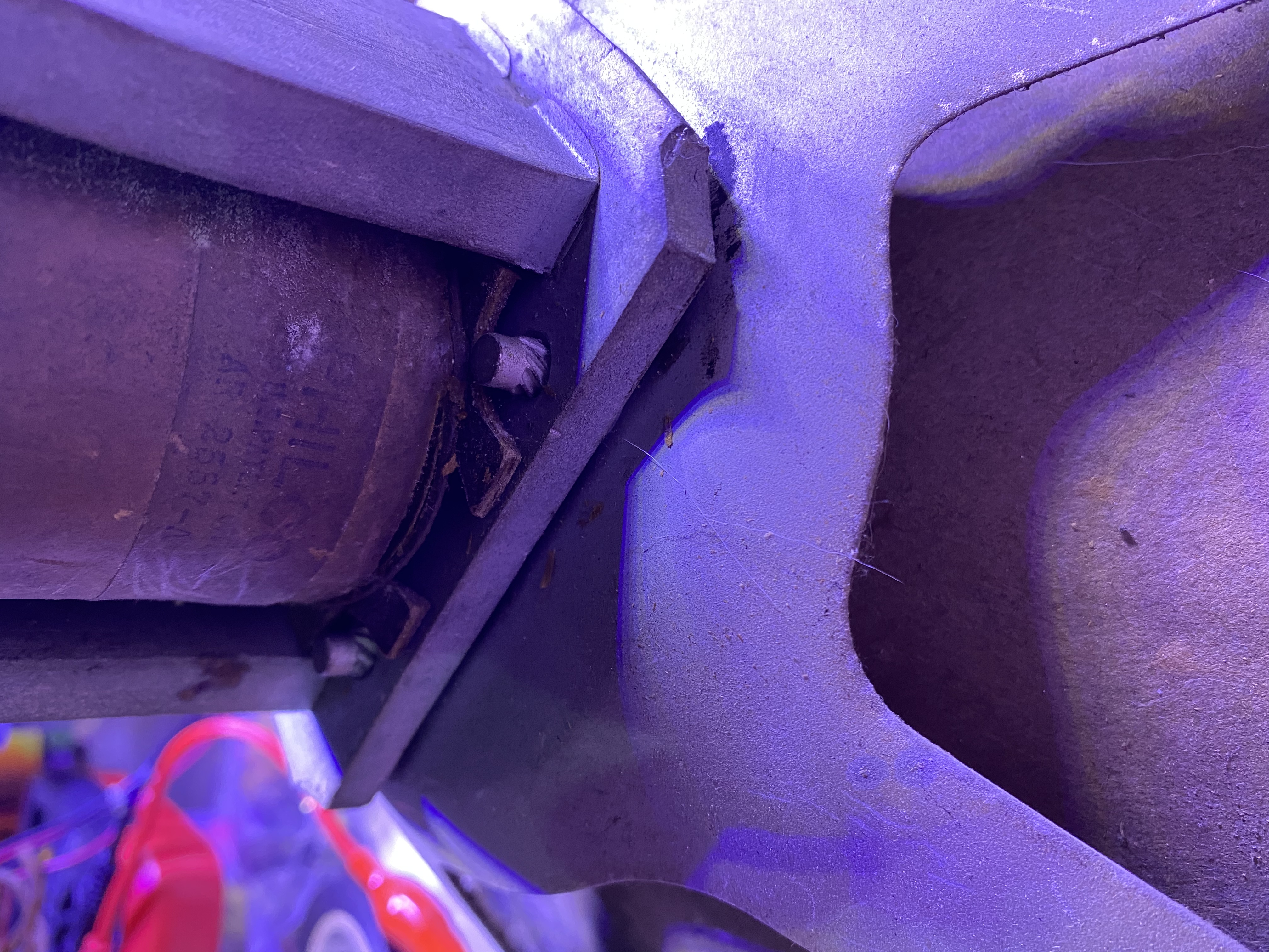
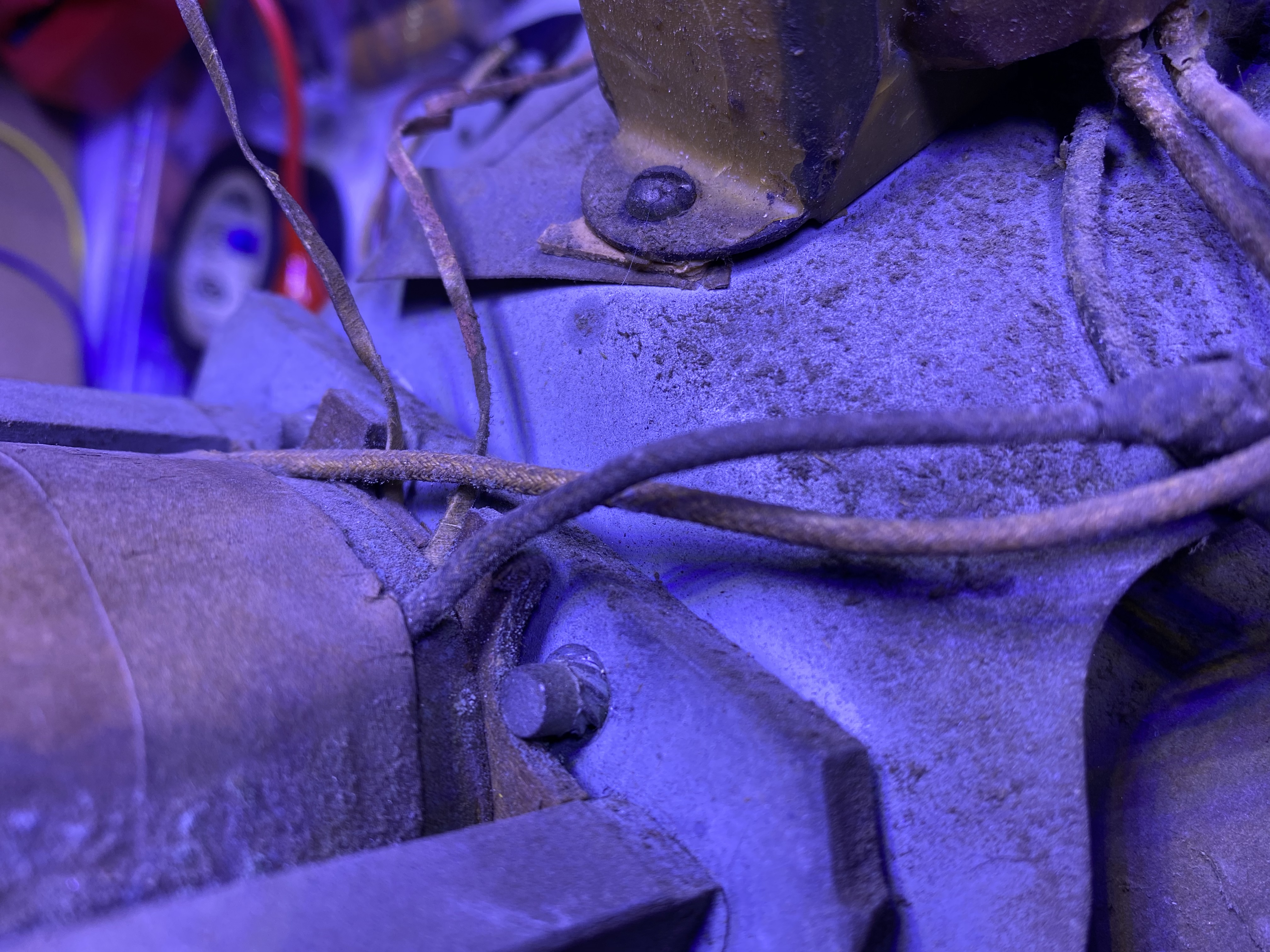
I cannot, for the life of me, figure out how these strange smooth-headed bolts are keeping this thing in short of “they just pounded them in”
So... do I just pound them back out, in reverse?
Check out these weird twisty attachment things at the corners. The other side is a smooth round bolt head. Nothing to turn.
Before I proceed on a “gosh, you’re kinda not all the bright, are ya?” course of action... is there something about these I’m just not seeing that should be obvious?


Knows enough to be dangerous, occasionally successful, rarely correct.
Posts: 1,114
Threads: 14
Joined: Feb 2013
City: Irvington, NY
That's exactly what they are "just pounded in". They are called drive rivets and are driven in by force. To remove just drive with a punch in the reverse direction.
Posts: 12
Threads: 1
Joined: Oct 2021
City: Bluemont
State, Province, Country: VA
Thanks! That's what it looked like, but I didn't want to start whackin' away on this thing without being certain.
Knows enough to be dangerous, occasionally successful, rarely correct.
Posts: 13,776
Threads: 580
Joined: Sep 2005
City: Ferdinand
State, Province, Country: Indiana
Instead of going to all that trouble to end up with a hacked-up "repair", why not send the original speaker to Rich Stamer at Sound Remedy in NJ for a recone? Then you will have a good, working speaker with no need to hang extra parts somewhere. Just a thought.
--
Ron Ramirez
Ferdinand IN
Posts: 2,135
Threads: 158
Joined: Jan 2013
City: Westland, MI
+1 what Ron said. Without an arbor press to push those rivets out you take too much of a chance of bending the frame. Speaker rebuilds aren't that expensive. Keep it original if you can. Just my two cents. Take care and BE HEALTHY! Gary
"Don't pity the dead, pity the living, above all, those living without love."
Professor Albus Dumbledore
Gary - Westland Michigan
Posts: 12
Threads: 1
Joined: Oct 2021
City: Bluemont
State, Province, Country: VA
This is why I love this forum. Beautiful info.
Ok, I’m not gonna air any laundry. This thing absolutely has to “work” soon.
After that, I will have opportunity to do it right. I started out with that intention, and now my goals have (momentarily) changed.
This isn’t for me. It was. It’s now a tad beyond me.
Back to immediate topic:
And I was super-duper careful on removing those rivets. I did consider that the frame might deform. A little penetrating oil (seriously tiny amount) and a few taps over a cushion had them out. Speaker frame is solidly intact and bend-free.
Ron- I want this original for me and my kids
and my grandkids to span so many generations. I will reach out to that fellow once my present purpose has been fulfilled and see if I can’t get that speaker fixed.
Until then, I will have to make good-enough, “good enough”
Knows enough to be dangerous, occasionally successful, rarely correct.
Posts: 12
Threads: 1
Joined: Oct 2021
City: Bluemont
State, Province, Country: VA
Last little “PS”-
I want to be as good as you all. If not 100%, at least as close as my ability can reach.
I don’t have the skill, nor even close to the experience, but I want it. And I will do my best to learn and also, hopefully also sometimes, be able to answer these simple questions.
Knows enough to be dangerous, occasionally successful, rarely correct.
Posts: 13,776
Threads: 580
Joined: Sep 2005
City: Ferdinand
State, Province, Country: Indiana
--
Ron Ramirez
Ferdinand IN
Users browsing this thread:
|
|
Recent Posts
|
|
Need to purchase some accessories for restoration of my Old Philco Radio
|
| Hi Paulo,
Welcome to the Philco Phorum.
I can see why you want to find good reproduction parts. That is a bea...MrFixr55 — 11:10 PM |
|
HiFi (Chifi) tube amp build - but my own design.
|
| Tim,
I have some bakelite sockets in my work shop that I can dig up. I believe quite a few are NOS. I will take photo...RodB — 10:03 PM |
|
Philco 610B oscillator wiring
|
| > The cathode as noted is wired directly to the ground side of the heater filament for that tube, not to the #17 and ...Radioroslyn — 08:12 PM |
|
HiFi (Chifi) tube amp build - but my own design.
|
| Tim;
I noticed your post a little late, but I would take one of the junk sockets and try to break a chunk out of it wi...Arran — 08:07 PM |
|
Need to purchase some accessories for restoration of my Old Philco Radio
|
| Here is a list of resources found in our online library that you might find useful. Mike's Gobs of Knobs email addres...klondike98 — 01:46 PM |
|
First Radio restoration
|
| Hi Tubeman,
Welcome to the Philco Phorum. Phamily Phriendly Pfun with Phine Pholks Phull of Philco Phacts. (See a p...MrFixr55 — 12:33 PM |
|
First Radio restoration
|
| You could post in the WANTED ADs section here on the Phorum and see if anyone has an RF generator that they want to sell...klondike98 — 11:55 AM |
|
Zenith H725
|
| Good ideas, thank you Arrange and Rich. I have the adhesive aluminum foil already and can try that immediately.
More ...EdHolland — 10:18 AM |
|
Graphics for majestic 1050 dial glass.
|
| Murf;
I found this thread on the ARF, the first photo has a pretty good view of the dial glass.
Regards
ArranArran — 01:12 AM |
|
Zenith H725
|
| hello Ed,
how about that speacial tape used for ducting it's like foil or how about thin piece of
aluminum roof flash...radiorich — 12:19 AM |
|
Who's Online
|
| There are currently no members online. |

|
 
|


![[-] [-]](https://philcoradio.com/phorum/images/bootbb/collapse.png)


