Zenith 7s488 assistance request
Posts: 104
Threads: 9
Joined: Sep 2017
City: York
State, Province, Country: PA

Hi Guys,
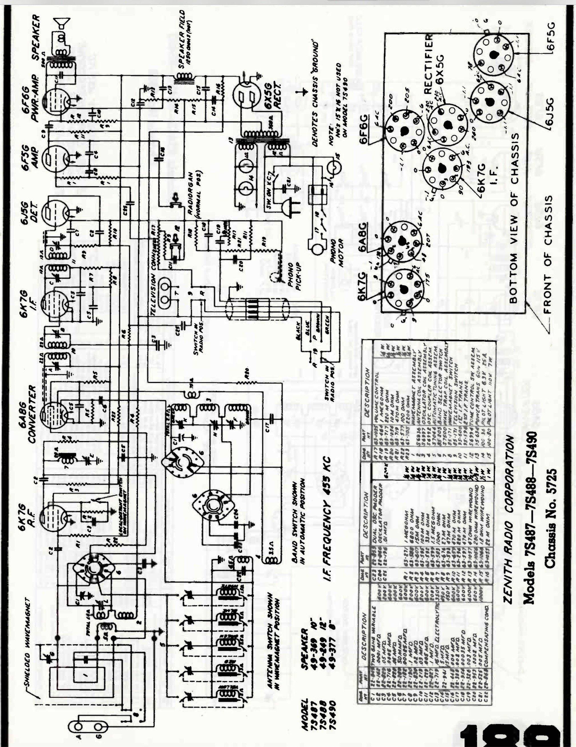
I’m in need of some help with a Zenith 7s488. I’ve recapped the radio and have the audio section working. I’m getting some bad voltage readings from some of the tubes. These voltages were recorded at 80 volts on a variac.
6K7G (RF)- P 205 v., G2 0 v., G3 0 v., G1 0 v.
6A8G (Converter) - P 0 v., G2 235 v.
6K7G (IF) - P 213 v., G2 0 v., G3 0 v.
6J5G (Det) - G 0 v.
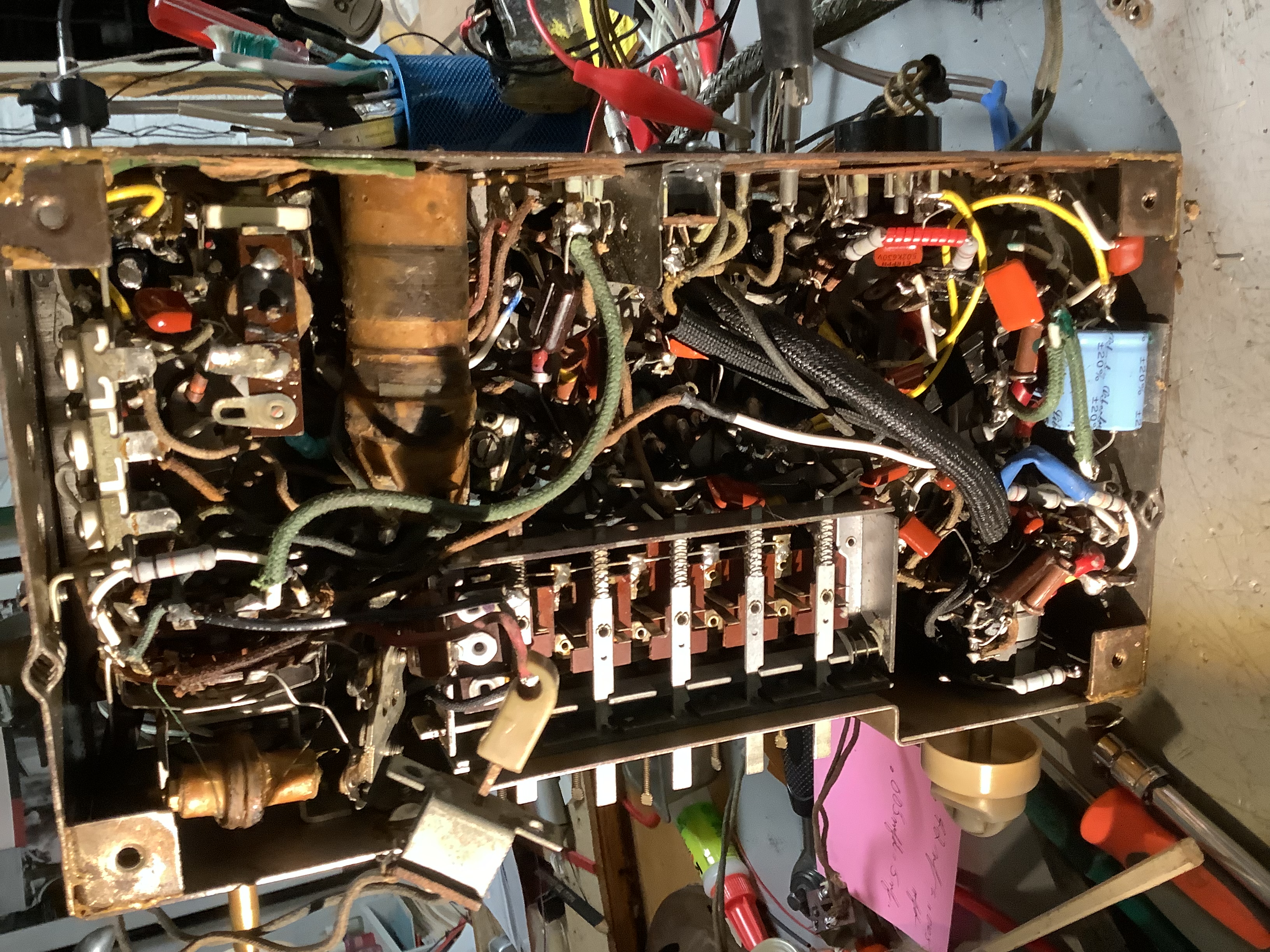
I didn’t include readings from the 6X5G, 6F5G and 6F6G because they are apparently functioning. Transformers and coils show continuity so I assume they are good. This is a tough radio to work on because everything is packed tightly. Any direction from the Phorum Pfolks is appreciated. Thanks. - Rob Q.
Posts: 16,483
Threads: 573
Joined: Oct 2011
City: Jackson
State, Province, Country: NJ
Your primary of the RF transformer (that goes to the plate where it reads 0V) is likely open. Start there.
And for good measure, if you have no smoke, do the readings at 110VAC.
People who do not drink, do not smoke, do not eat red meat will one day feel really stupid lying there and dying from nothing.
Posts: 104
Threads: 9
Joined: Sep 2017
City: York
State, Province, Country: PA
Thanks morzh. I’ll get to work and report back. - Rob Q.
Posts: 104
Threads: 9
Joined: Sep 2017
City: York
State, Province, Country: PA
The rf transformer checked out fine but I suspect that the problem isn’t far away. The leads of the primary go to two solder connect points with multiple wire leads so I’ll go there next unless someone has another idea. Thanks! - Rob Q.
Posts: 3,149
Threads: 56
Joined: Apr 2011
City: Lexington, KY
Just to be clear, if you have 0 volts on the plate of the 6A8 (converter) did you ohm out the primary of IF coil #10? It looks like it should be about 22 ohms.
John KK4ZLF
Lexington, KY
"illegitimis non carborundum"
Posts: 104
Threads: 9
Joined: Sep 2017
City: York
State, Province, Country: PA
Yes I did. It is 22 ohms on the dot.
Posts: 1,218
Threads: 11
Joined: Jul 2020
City: Greenlawn
State, Province, Country: NY
Hi Rob,
This is an interesting issue, as the 1st IF Primary connects directly between the 6A8 plate and the B+ Bus (that supplies B+ to Audio and through resistors, to the plates and screens of the other tubes) and the B+ Bus is working. I would look for a cold solder joint. One technique:
Confirm the resistance of the 1st IF Primary again. At the exact same points that you are measuring the resistance, without moving your leads (Test clips help here), switch the DVM to DC Volts and fire up the radio. If you see a voltage in the 200V Range, then a bad connection exists between the 2 points that you are measuring. This can be a cold or a poorly soldered joint inside or outside the 1st IF transformer. The resistance reading is good due to the very low voltage and low current put out by the DVM.
However, if the voltage across this point is close to 0V, then look elsewhere, but you are close. I do not suspect that the plate voltage is 0V due to a short in the tube or at the socket, as this would put the full 250V B+ across the 1st IF Primary winding and burn it out!
After resolving this, I would worry about the 6A8. With no plate voltage (and no plate current), then the various grids connected to B+ will handle all the current and possibly burn up, shorting against adjacent grids. This is very common in the output stage of radios if operated without the output transformer connected. This is why most radios of this vintage that have the transformer mounted on the speaker and connected to the Output tube via a plug also interrupt B+ to the rest of the chassis when the speaker plug is disconnected.
Hope this helps. Good Luck.
Best Regards,
John, MrFixr55
"Do Justly, love Mercy and walk humbly with your God"- Micah 6:8
"Let us begin to do good"- St. Francis
Best Regards,
MrFixr55
Posts: 104
Threads: 9
Joined: Sep 2017
City: York
State, Province, Country: PA
Thanks for your input John. I’ll follow through with your suggestions.
After recapping, cleaning tube pins, variable capacitor, switches and contacts the bc band was working, along with the preset push buttons. When I went back to work on it the next day the radio had reverted to nonfunctional mode.
I’m sending a picture of the chassis. It’s definitely crowded inside! Thanks again! - Rob Q.

Posts: 104
Threads: 9
Joined: Sep 2017
City: York
State, Province, Country: PA
Hi Guys- Following John’s suggestion I found a reading of 0 v. DC. All tubes were tested earlier in the process but a second check of the 6A8G found the tube dead. I’ll order another one today. My question is whether another issue took out the tube, or was it just ready to go after 70+ years? Thanks again for the help guys! - Rob Q.
Posts: 16,483
Threads: 573
Joined: Oct 2011
City: Jackson
State, Province, Country: NJ
Rob
This is not a higher math.
Take a meter, set it on volts, and strart going along the line of feeding the power to the 6A8 plate. 0V? OK, how about the other side of that same RF transformer primary? Again 0V? Go tro the bus it is connected to. Itr is literally 5 minutes to trace.
People who do not drink, do not smoke, do not eat red meat will one day feel really stupid lying there and dying from nothing.
Posts: 104
Threads: 9
Joined: Sep 2017
City: York
State, Province, Country: PA
I’ll do that. Sounds logical.
Posts: 3,149
Threads: 56
Joined: Apr 2011
City: Lexington, KY
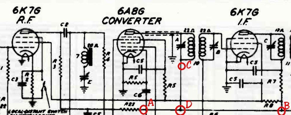
If you have voltage on the plate of 6K7 (RF) and the plate of 6K7 (IF) then something must be wired incorrectly. Check both sides of the IF (#10) for voltage. Then check at R23 and then the junction of R8 & R7. If you have voltage at the resistors but none on either side of the IF (#10) then it isn't connected to where it should be.
In-other-words, if you have voltage at point A and B but not C, then there must be a disconnect between point C and D.

John KK4ZLF
Lexington, KY
"illegitimis non carborundum"
(This post was last modified: 07-28-2022, 04:34 PM by Eliot Ness.)
Posts: 104
Threads: 9
Joined: Sep 2017
City: York
State, Province, Country: PA
I had wired the IF incorrectly. 6A8G plate voltage is back. Still no radio reception. I’m waiting for a NOS 6A8G to arrive. When the one I have is in the tube tester, readings are all over the place. It would be nice if that’s all that is wrong with the radio, but I’m not getting my hopes up yet. I’ll let you know what happens. Thanks guys! - Rob
Posts: 1,218
Threads: 11
Joined: Jul 2020
City: Greenlawn
State, Province, Country: NY
Good Deal Rob! I was wondering if here was a miswire, but was going with a cold solder joint first. I gotta get around to learning how to easily cut, markup and paste sections of a schematic like Elliot Ness did in his last post.
I have a sneaking opinion that the 6A8 is toast. Good luck!
"Do Justly, love Mercy and walk humbly with your God"- Micah 6:8
"Let us begin to do good"- St. Francis
Best Regards,
MrFixr55
Posts: 104
Threads: 9
Joined: Sep 2017
City: York
State, Province, Country: PA
Hi Guys-
A new 6A8 didn’t get the radio functioning. I’ll go back through and recheck tube voltages at 110 v. Since the AF section works maybe I should focus on the IF portion next. Any and all suggestions are appreciated. Thanks. - Rob
Users browsing this thread: 1 Guest(s)
|
|
Recent Posts
|
|
Need Help to ID this radio 11 tube Philco
|
| Yes the 16B as morzh pointed out. Specifically its the January 1935 model version of the 16B. There are a couple earli...klondike98 — 11:51 PM |
|
48-482 rear panel help
|
| Welcome to the Phorum, keithchip! How far you take a radio on cabinet restoration is a matter of personal preference. ...GarySP — 11:28 PM |
|
48-482 rear panel help
|
| I've recently finished the internal restoration of a locally purchased Philco 48-482. The cabinet is in ok shape except ...keithchip — 10:28 PM |
|
Need Help to ID this radio 11 tube Philco
|
| Welcome to the Phorum, Ken! Lots of help here for all of your restoration questions. Take care and BE HEALTHY! - Gar...GarySP — 07:59 PM |
|
Need Help to ID this radio 11 tube Philco
|
| Thank you.
I went to your online library and found 2 schematics.
I will download and compare to components!Ken D. — 06:31 PM |
|
Need Help to ID this radio 11 tube Philco
|
| It is a 16B tombstone.morzh — 06:13 PM |
|
Zenith H725
|
| David - sorry, I reread your post and finally saw THD - now the % figures make sense. Thanks for explaining.
The PSU...EdHolland — 06:06 PM |
|
Need Help to ID this radio 11 tube Philco
|
| Hi Everyone,
New member but have been reading this for awhile for tips!
Vaccum tubes were before my time so bear with ...Ken D. — 06:03 PM |
|
My Philco 37-116 Restore
|
| Thank you MrFixR55, I appreciate your comments very much. I do not detect much hum if any so I will be staying with the ...dconant — 05:15 PM |
|
My Philco 37-116 Restore
|
| Hi DConant
Yes, you can replace chokes with resistors. You do stand the risk of increased hum. the solution is to inc...MrFixr55 — 04:23 PM |
|
Who's Online
|
| There are currently no members online. |

|
 
|


![[-] [-]](https://philcoradio.com/phorum/images/bootbb/collapse.png)


