Philco 46-1226: Strange Volume Problem
Posts: 9
Threads: 1
Joined: Apr 2023
City: North Plainfield
State, Province, Country: NJ
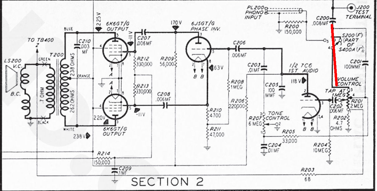
New member here. I'm in the process of restoring a Philco 46-1226, code 125. Unfortunately, the condition it came to me in prevented me from testing it prior to the work I did. I say that because I don't know if the issue I'm dealing with was preexisting or the result of something I did during my work. The issue? When listening to AM, increasing the volume (turning the knob clockwise) causes the output from the speaker to decrease. This doesn't happen when I inject a sine wave into the phono input, i.e. the volume works as you'd expect.
I've replaced all of the electrolytic and paper caps throughout the unit and also swapped out any grossly out-of-spec resistors. I tested all of the tubes with my B&K 550 and replaced any that tested weak. If anyone has any ideas or has encountered this oddity before, please weigh in.
Thanks.
Posts: 16,582
Threads: 574
Joined: Oct 2011
City: Jackson
State, Province, Country: NJ
How'bout a simple stupid thing like inverting the volume pot 1st dn 3rd pins?
People who do not drink, do not smoke, do not eat red meat will one day feel really stupid lying there and dying from nothing.
Posts: 9
Threads: 1
Joined: Apr 2023
City: North Plainfield
State, Province, Country: NJ
I'd love to find a simple, stupid fix. But since it works properly when using the phono input, I think the volume pot itself is fine.
Posts: 16,582
Threads: 574
Joined: Oct 2011
City: Jackson
State, Province, Country: NJ
Check the Phono/AM switch. It is possible it does not make a good connection when in "Radio" position, and the signal goes through C26, in which case the volume pot would increase volume whgen going CCW.
The volume itself should be pretty low, lower than normal.
People who do not drink, do not smoke, do not eat red meat will one day feel really stupid lying there and dying from nothing.
Posts: 9
Threads: 1
Joined: Apr 2023
City: North Plainfield
State, Province, Country: NJ
Yes, even when the volume is at max CCW, the output in AM is still lower than I would expect.
I'll check the switch (again). I've cleaned it a few times, but perhaps there's still oxidation on the contacts.
Posts: 16,582
Threads: 574
Joined: Oct 2011
City: Jackson
State, Province, Country: NJ
Do an experiment. Short out the switch by a piece of wire. Or simply desolder the wires and twist them together to fully exclude the switch and possible wrong connections.
People who do not drink, do not smoke, do not eat red meat will one day feel really stupid lying there and dying from nothing.
Posts: 1,291
Threads: 11
Joined: Jul 2020
City: Greenlawn
State, Province, Country: NY
+1 on Morzh's idea to jumper the switch.
Not much should come through C26 as it is 100 pF (0.00001 uF), unless it is shorted. Also, look at the tone control. Some weirdness could happen if the wiper no longer connects to the resistance track.
BTW, with the Push Pull 6K6s (Successor to the 41), Cathodyne Phase invertor and the negative feedback, this should be no slouch of a receiver.
"Do Justly, love Mercy and walk humbly with your God"- Micah 6:8
"Let us begin to do good"- St. Francis
Best Regards,
MrFixr55
Posts: 9
Threads: 1
Joined: Apr 2023
City: North Plainfield
State, Province, Country: NJ
I measured the resistance between the point after C200 (which is new) to the volume pot, and it was around .03 ohms. So I think that rules out the switch.

Posts: 16,582
Threads: 574
Joined: Oct 2011
City: Jackson
State, Province, Country: NJ
Somehow Rider's sch has different ref. designators on parts, but that's OK.
How about the volume pot, does it show correct end-to-end resistance and the wiper action? (I am driving at the top pot lug being disconnected due to a crack in the top pafrt of the rheostat).
People who do not drink, do not smoke, do not eat red meat will one day feel really stupid lying there and dying from nothing.
Posts: 1,291
Threads: 11
Joined: Jul 2020
City: Greenlawn
State, Province, Country: NY
Check the volume and tone control wiring and parts carefully. an open or wrong 4.7 ohm resistor between the pot and chassis ground may wreak havoc, as that is the injection point for negative (?) feedback.
"Do Justly, love Mercy and walk humbly with your God"- Micah 6:8
"Let us begin to do good"- St. Francis
Best Regards,
MrFixr55
Posts: 9
Threads: 1
Joined: Apr 2023
City: North Plainfield
State, Province, Country: NJ
Thanks guys. I'll check as suggested and circle back with what I find.
Posts: 16,582
Threads: 574
Joined: Oct 2011
City: Jackson
State, Province, Country: NJ
It is a neg. feedback.
Inversion of the output winding or the plate wires of the primary of the output xfmr would also create an interesting behaviour.
Though it probably would manifest itself a bit different....like howling.
Had it once in a Grundig. Boy did it howl.....
People who do not drink, do not smoke, do not eat red meat will one day feel really stupid lying there and dying from nothing.
Posts: 9
Threads: 1
Joined: Apr 2023
City: North Plainfield
State, Province, Country: NJ
The volume pot measures close to the spec'd 2 meg and tracks fine when rotating it while watching the needle of my Simpson 270. The 4.7 ohm and 68 ohm resistors connected to the one leg of the pot are ok.
The tone pot actually measures high compared to what it should be: 10 meg vs 6 meg. Granted, this is in circuit. The 33k resistor coming off of one leg is ok.
Posts: 16,582
Threads: 574
Joined: Oct 2011
City: Jackson
State, Province, Country: NJ
If the tone pot is higher in-circuit, it means it high or even higher (depending on the circuit) out of circuit.
This said, the tone pot almost does not matter in this situation.
What would happen if: (top/right is used as from the sch point of view, not physical locations)
1. Fully disconnect C200 top pin from J200 test terminal (fully disconnect, the pin should be unsoldered).
2. Fully disconnect C202 right pin from the volume pot's wiper terminal.
3. Connect that C202 pin to the J200 Test terminal.
Does the volume become loud, as if at maximum volume? (be careful with local stations).
People who do not drink, do not smoke, do not eat red meat will one day feel really stupid lying there and dying from nothing.
Posts: 9
Threads: 1
Joined: Apr 2023
City: North Plainfield
State, Province, Country: NJ
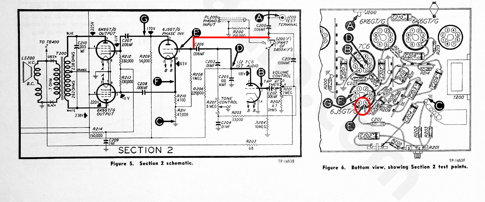
Figured it out. Turns out that when I replaced C206 I connected it to the lug for pin 6 of the 6J5GT, rather than pin 5. Lug 6 is unused for the tube, but acts as a tie point for where the radio signal goes to the bandswitch and C201 (part of the negative feedback?). I moved the C206 to pin 5 and correct volume operation was restored, and it was significantly louder than it had been before, which is no wonder.
Thanks for the help with this.

Users browsing this thread: 1 Guest(s)
|
|
Recent Posts
|
|
Philco Model 38-7: what caps & resistors do fail typically?
|
| Since you stated earlier, you have a console 38-7XX. They also had a 38-7T (table), and 38-7CS (chairside). A very nic...GarySP — 01:18 PM |
|
Part numbers to model cross
|
| That I wouldn't know, but sometimes the radio document itself shows one, same as the capacitor cans' etc pinouts.morzh — 12:46 PM |
|
Part numbers to model cross
|
| Thank you morzh, that is exactly what I was looking for. Now , is there some where that shows pinouts for Philco power ...Jim Dutridge — 11:37 AM |
|
Restoration of the Canadian General Electric A-87
|
| Thanks for your help Michael. In fact, this video is only an intermediate result. Later I had to apply another tinting l...RadioSvit — 09:01 AM |
|
Restoration of the Canadian General Electric A-87
|
| Great job on the cabinet.
PS. In the US notation, "kenotron" refers to specific type of tubes; we call re...morzh — 08:24 AM |
|
Part numbers to model cross
|
|
This document has at least some tables of models and parts used.
Example: Choke 32-7572, used in 604 radio.
Search f...morzh — 08:19 AM |
|
Restoration of the Canadian General Electric A-87
|
| I also checked all the radio tubes on my Hickok 530 tube tester. The 5Z3 kenotron turned out to be faulty, all the other...RadioSvit — 08:02 AM |
|
Restoration of the Canadian General Electric A-87
|
|
Well... While the varnish is drying up, I started repairing the chassis...
Of course I started by replacing the pa...RadioSvit — 07:12 AM |
|
Philco Model 38-7: what caps & resistors do fail typically?
|
| Hello Martin,
Welcome aboard our little community what great Model 38-7
Sincerely Richardradiorich — 12:30 AM |
|
Philco Model 38-7: what caps & resistors do fail typically?
|
| Welcome to the Phorum Martin.
I count about 9 paper caps, the 3 electrolytic caps and 2-Y2 safety caps to replace th...RodB — 09:44 PM |
|
Who's Online
|
There are currently 1213 online users. [Complete List]
» 1 Member(s) | 1212 Guest(s)
|
|
|

|
 
|


![[-] [-]](https://philcoradio.com/phorum/images/bootbb/collapse.png)


