Telefunken T6445GWK restoration
Posts: 16,476
Threads: 573
Joined: Oct 2011
City: Jackson
State, Province, Country: NJ
I have told the family story with this radio; my grandpa surreptitiosly procured one in 1949 (this is 1948 model), illegally (in the USSR of the time there was illegal to have any radio with working SW band) and then used it to listen to VOA and such, at low volume with his ear to the speaker, so the neighbors would not find out.
He told me about it, and then mom also remembered the same, and then I decided to find out about it, and some folks on the Russian-Ukrainian forum were helpful and told me what it was from my description, and then eventually about couple of months or so ago Peter found me one in Ukraine and shipped it to me. Surprisingly, he has a video of it working and pulling in stations.
When I showed it to mom over Skype video, she said "Oh....wait...is it a Telefunken?". She is 86. What a memory.
Anywho. I did not risk plugging it in, plus it was set to 220V anyway and will need to be set to 110-125VAC.
From the schematic of it, it seems to be an AC/DC set.
Today I eventually put it on the bench.
This is the schematic:
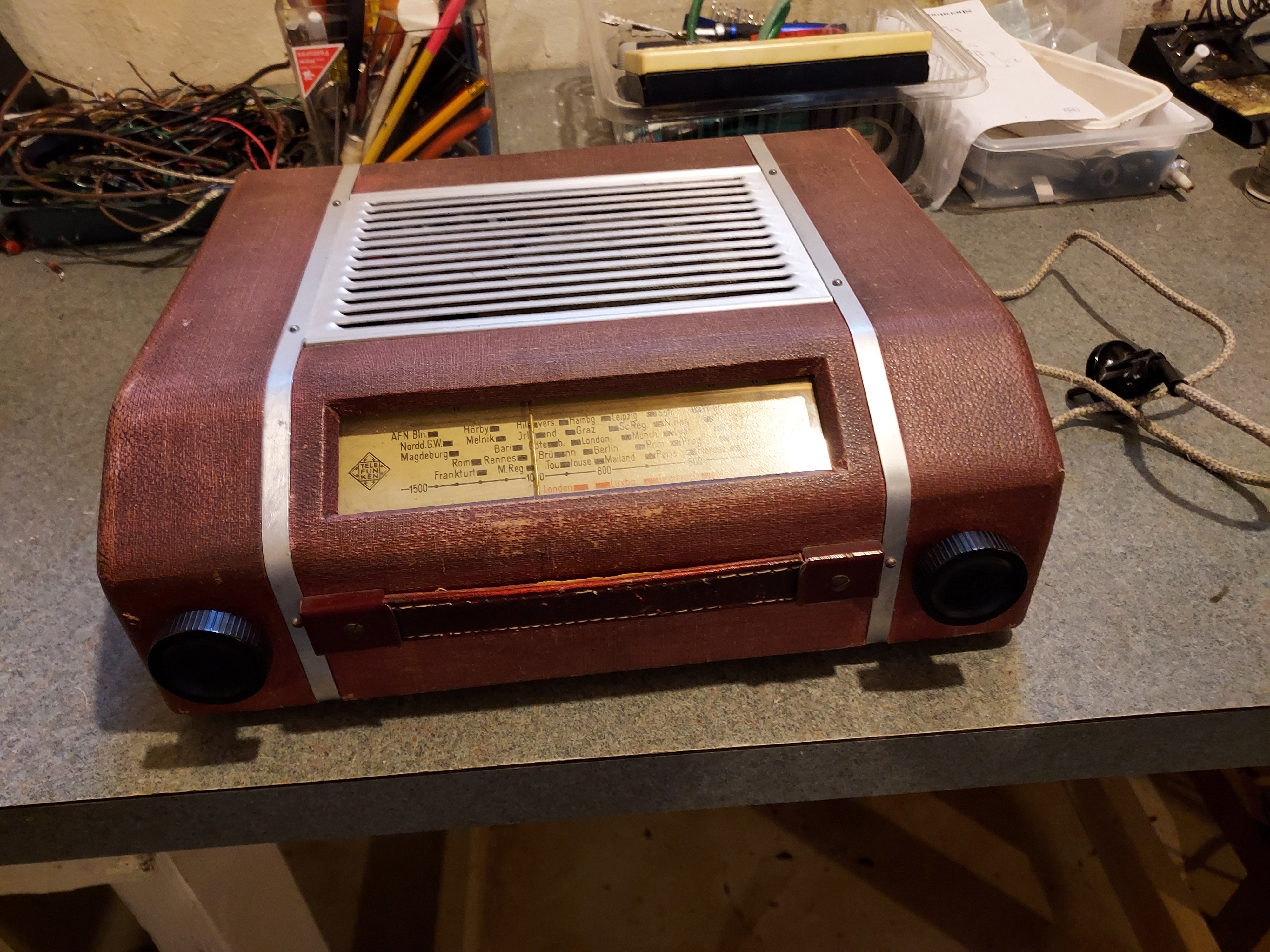
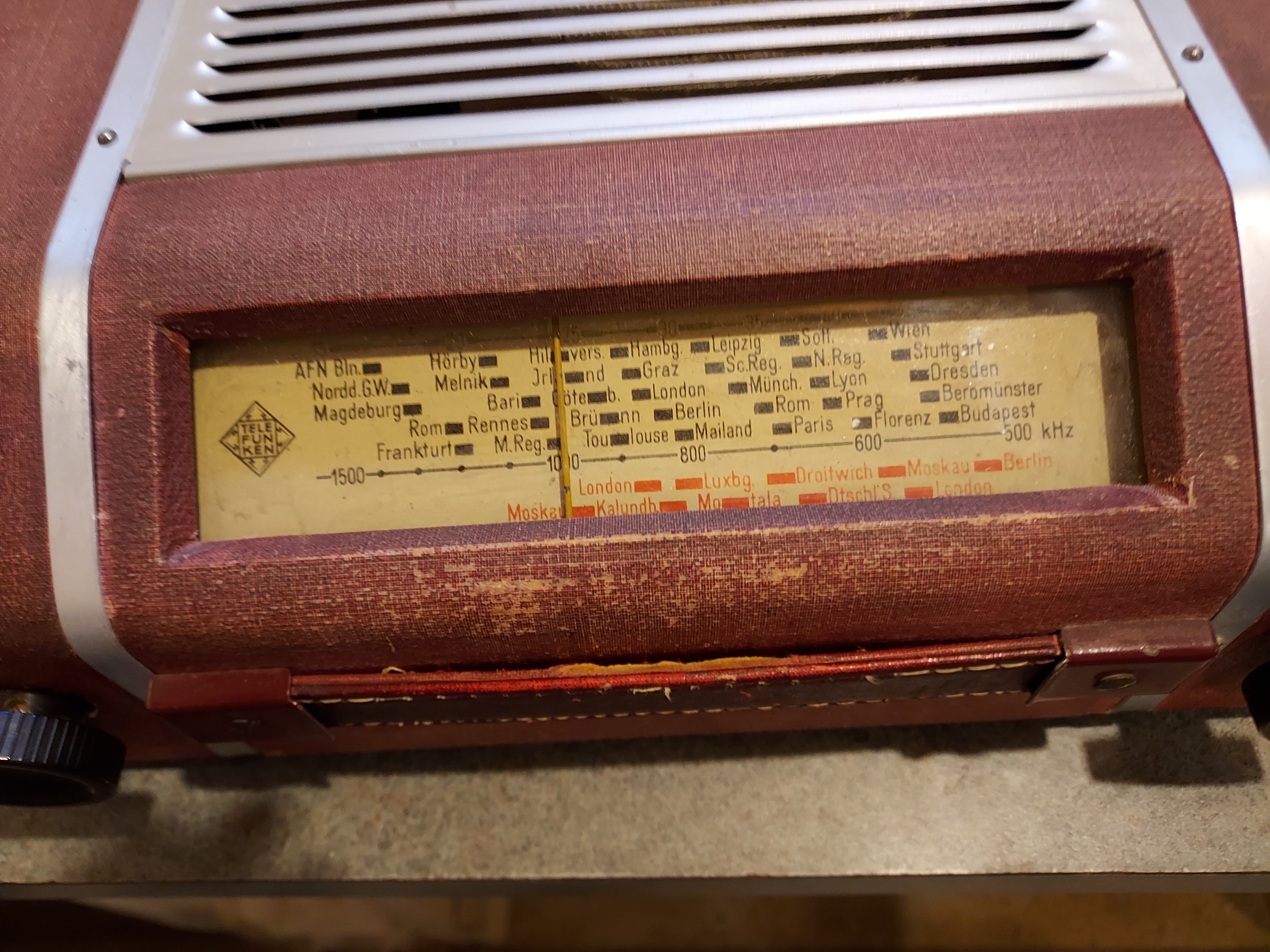
One tube (not sure what they call this type; steel case, and the pins have retaining locks on them) was out of socket but the speaker's magnet pulled it and so it did not bounce around, and one speaker retaining tab separated from the case; it will be a simple case of wood glue application.
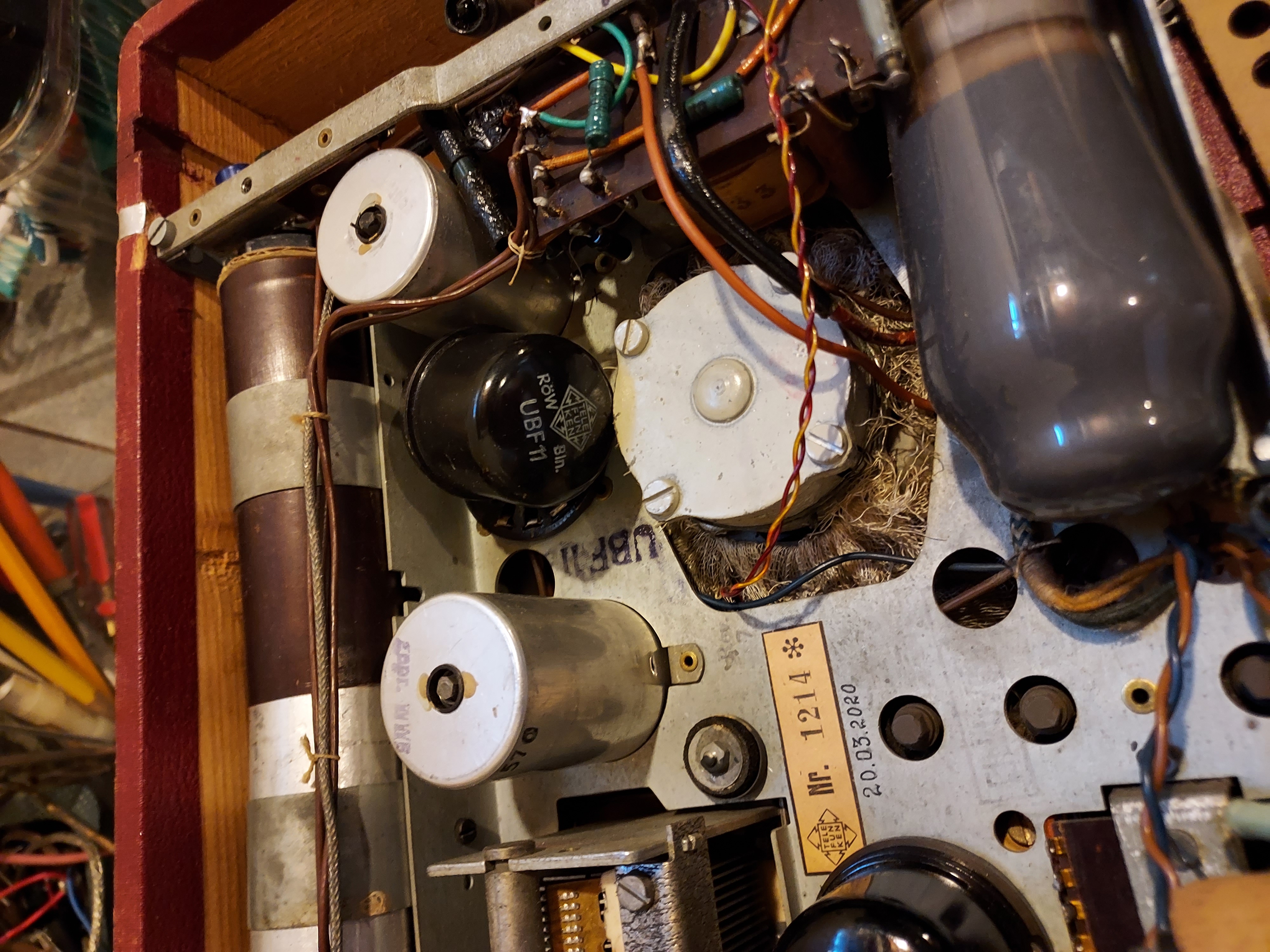
This is what the chassis look like
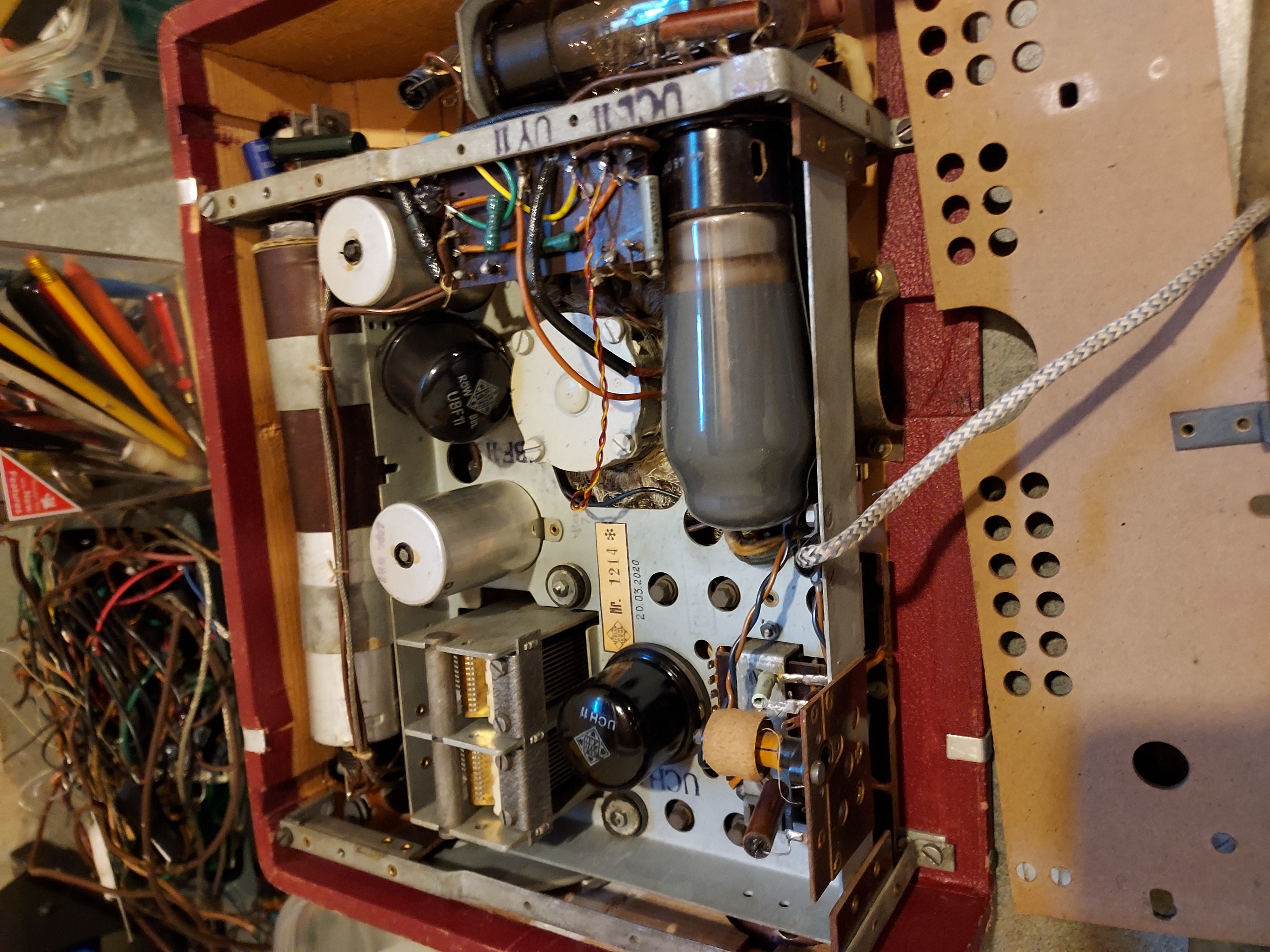
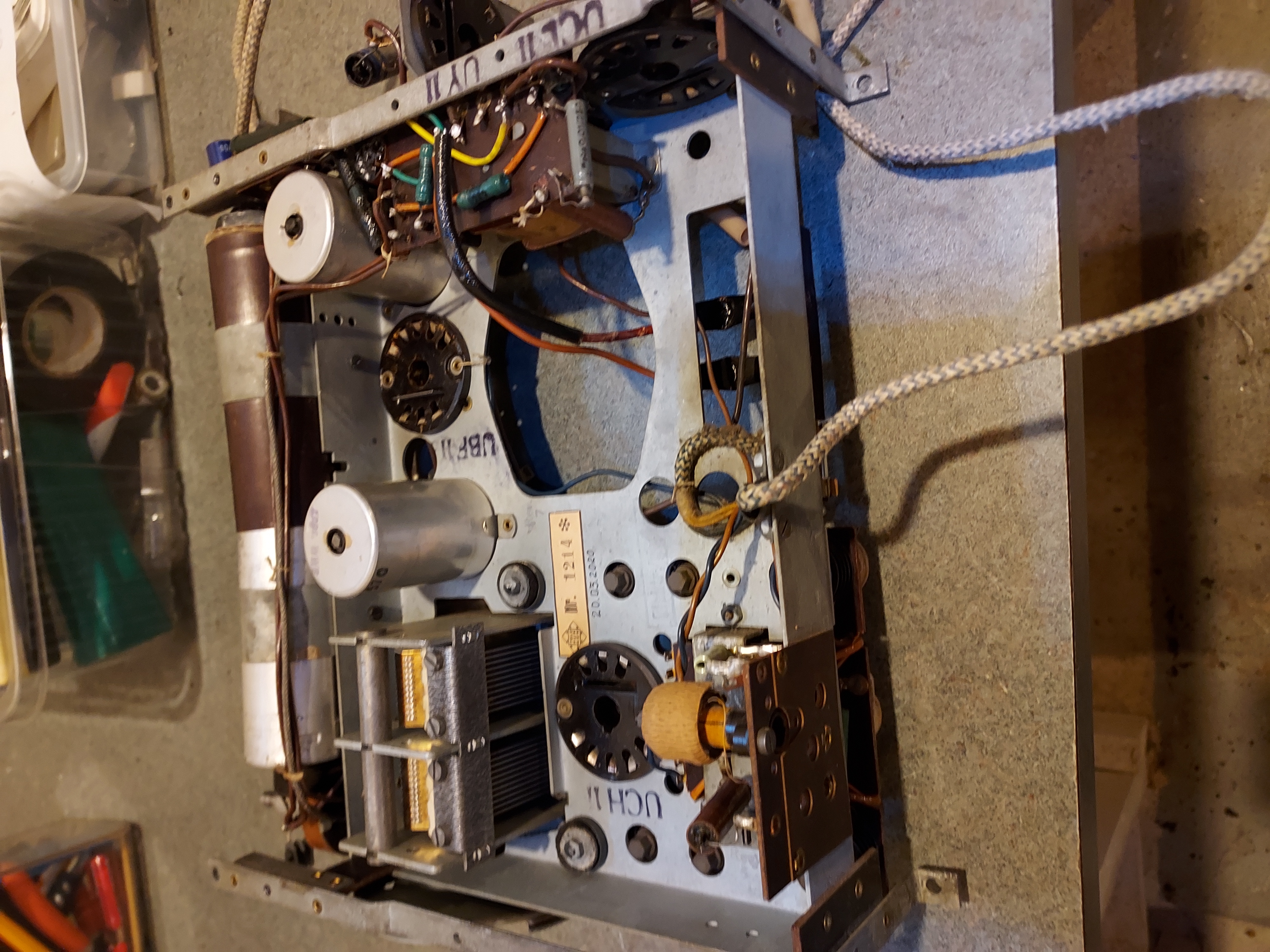
The set was touched up. So far there was no hacking, it was a pretty neat and discrete touch up.
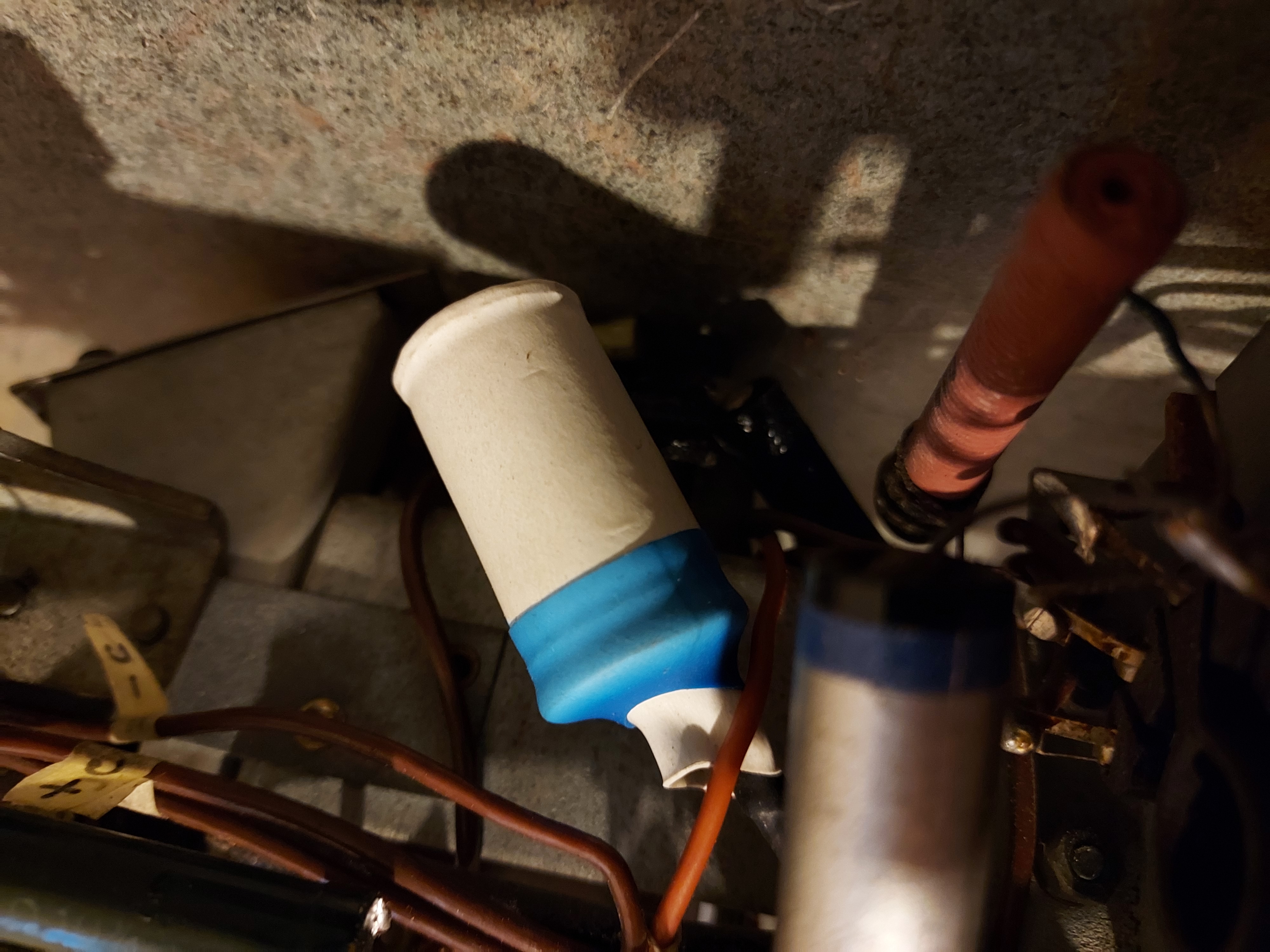
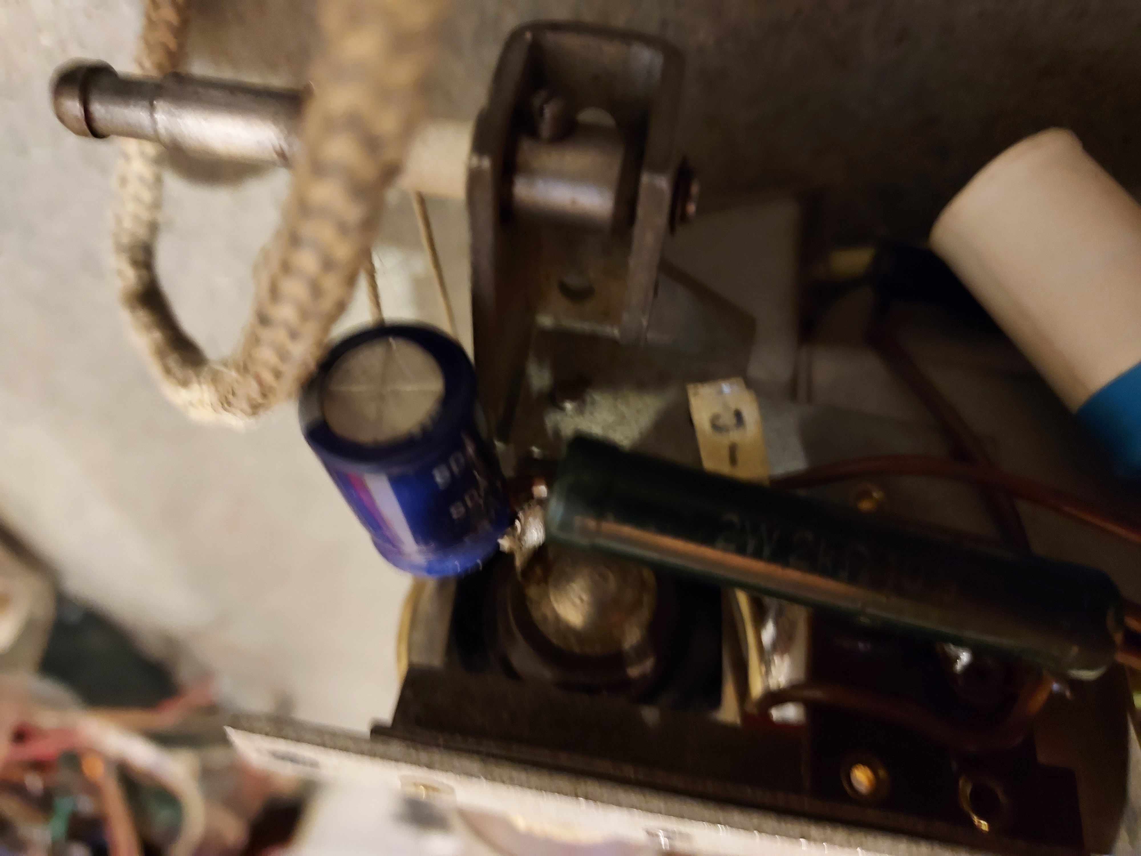
Not sure this resistor is original.
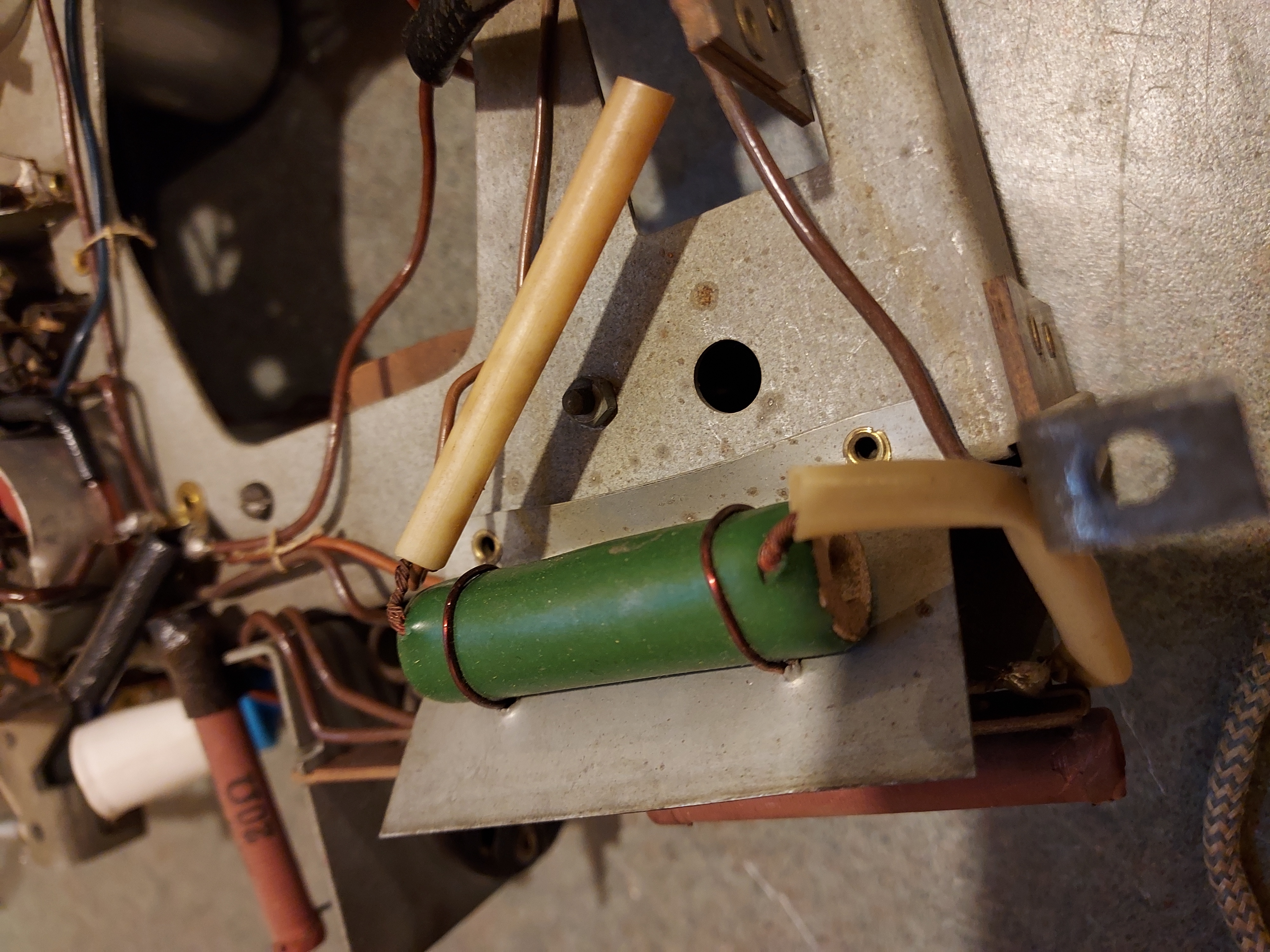
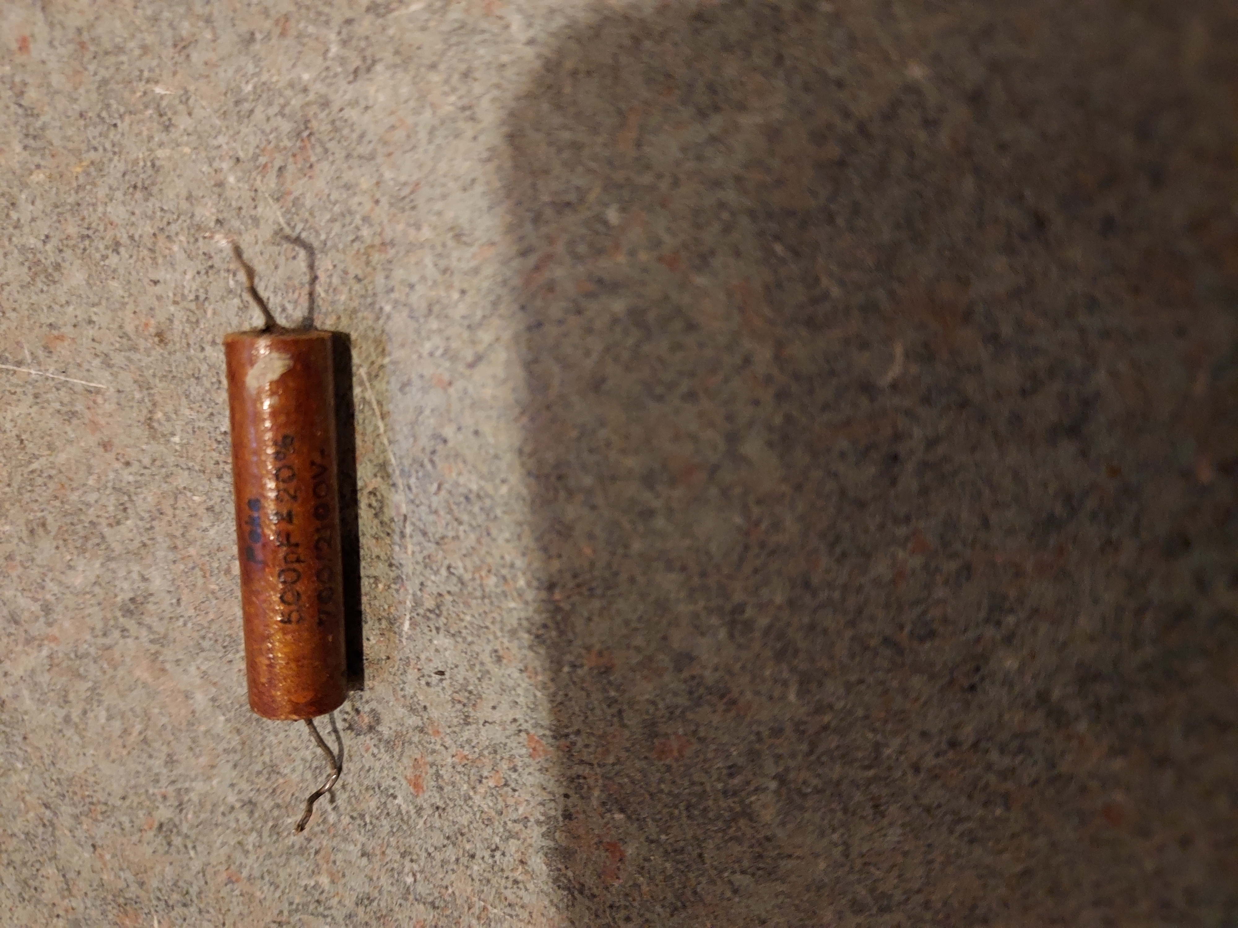
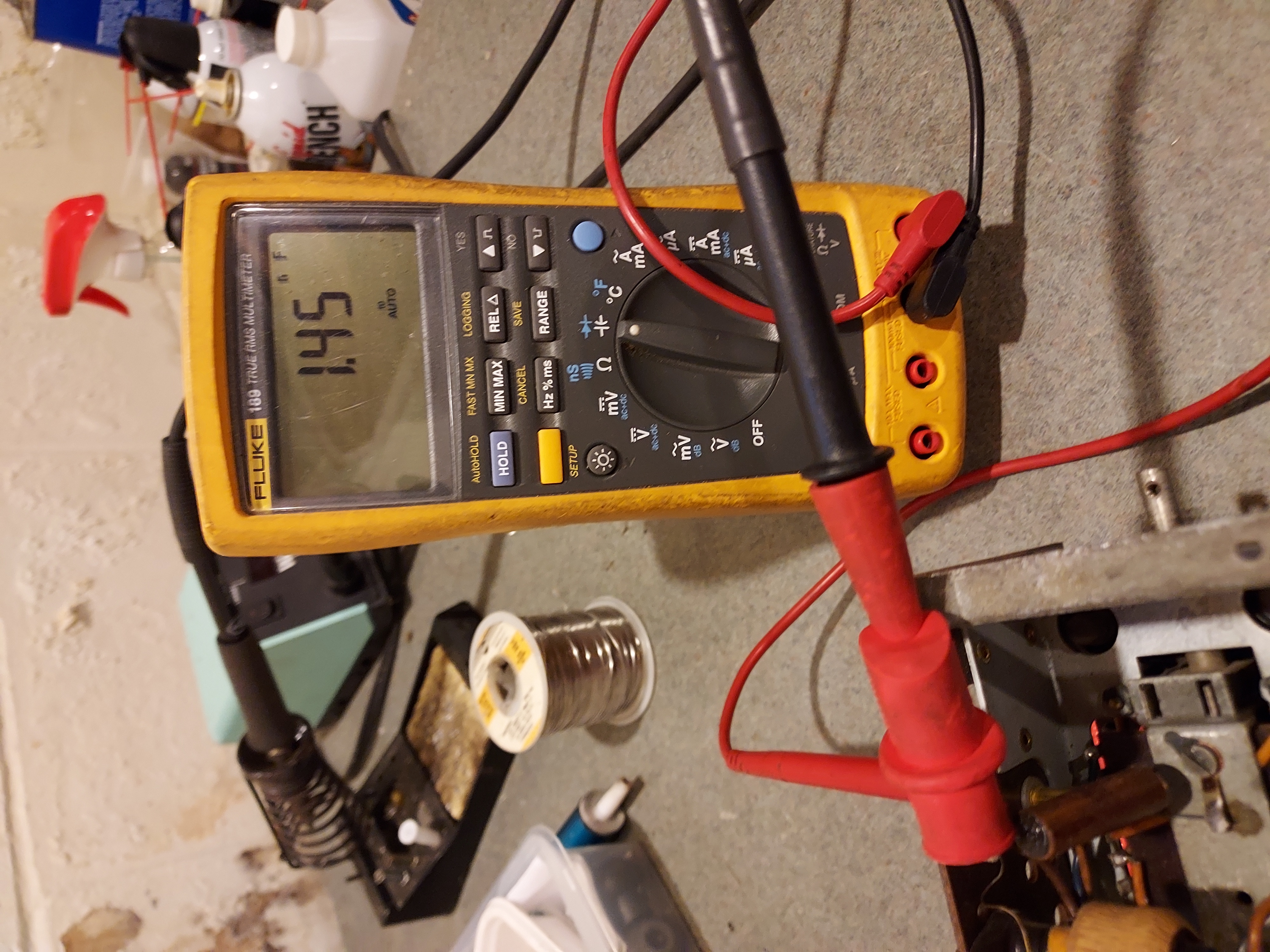
As usual, the recap is the first order of business. I will go though the tubular caps first. They are out of tolerance pretty badly even if not as bad as the ERO caps were in my Grundig. About double to triple. Then I will deal with the electrolytics.
Here I am measuring the antenna cap (the schematic and the written on the cap values are 500pF).
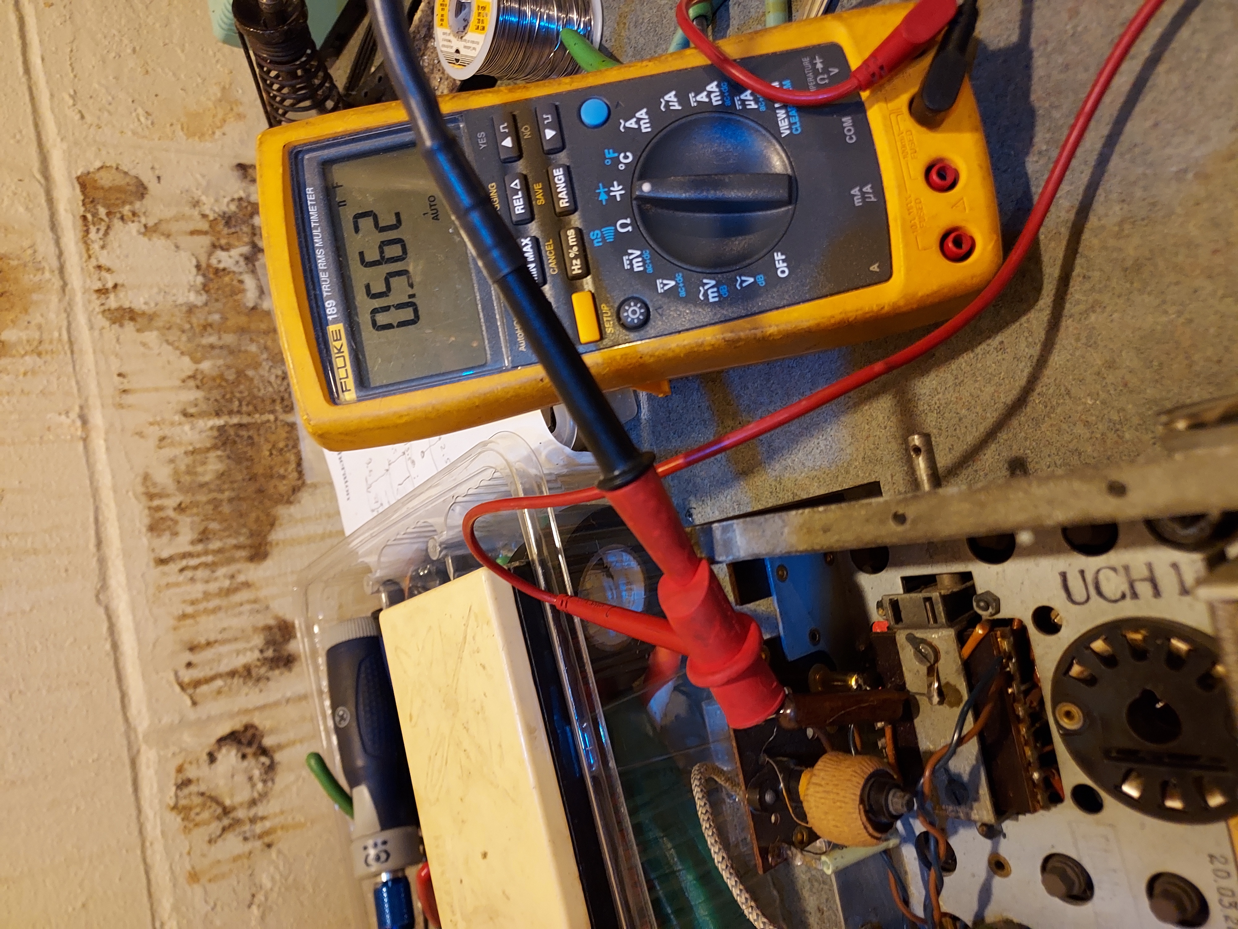
After the restuffing:
Same about the 20nF cap across the rectifier:
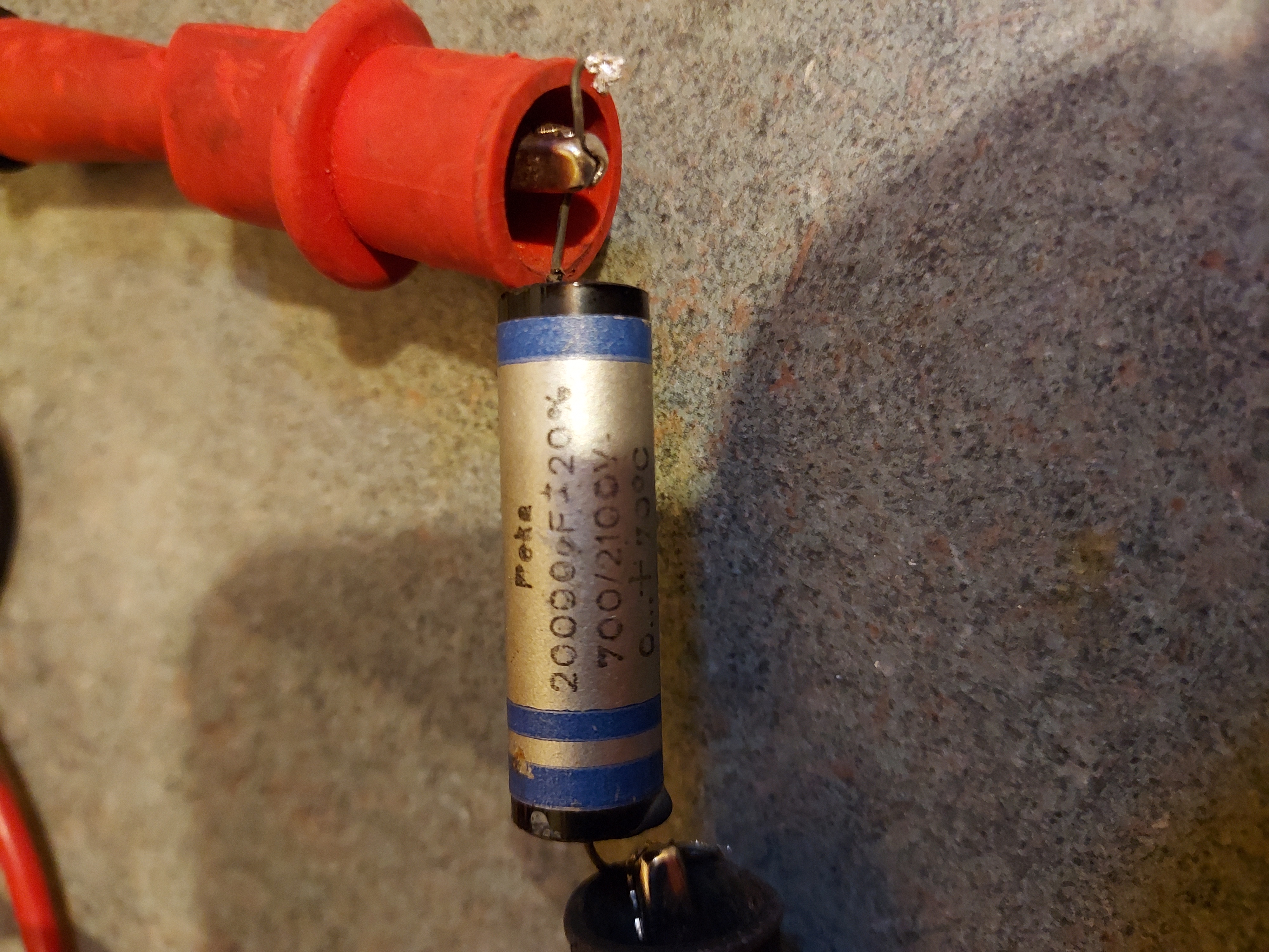
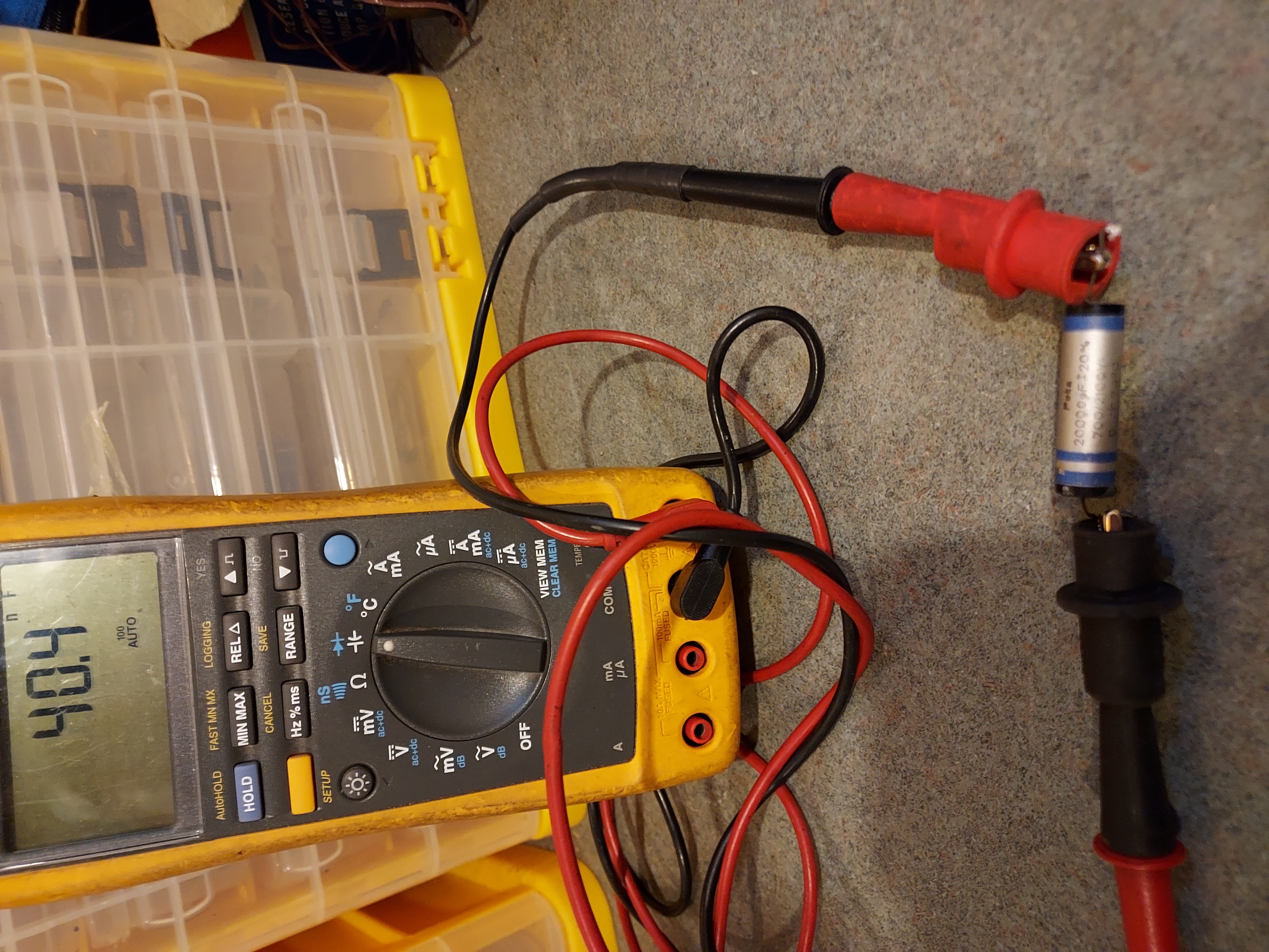
And after restuffing:
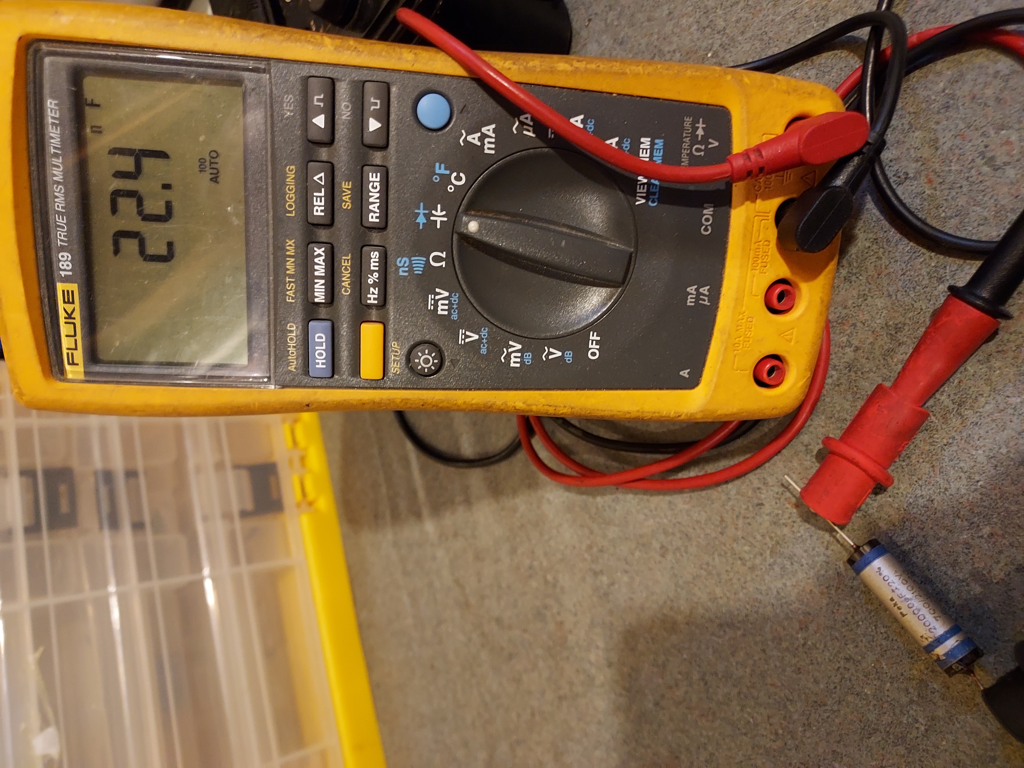
From the sch I see they seem to use the switch for the AC voltages. However I only see the wires soldered to the terminal lugs on the what appears to be an autotransformer that is used to bring the AC up to 220VAC from whatever Mains there is.
I will have to figure it out and probbaly resolder the contacts as I do not see any sort of switch there. Which might be a rightr thing to do, short of introducing interlocks to protect the sch from overvoltage.
So, enough for today.
People who do not drink, do not smoke, do not eat red meat will one day feel really stupid lying there and dying from nothing.
Posts: 622
Threads: 21
Joined: Nov 2014
City: Svalyava
State, Province, Country: Ukraine Transkarpati
Michael, here is a link to that video .
[Video: https://www.youtube.com/watch?v=Tuer0e2X4ZA]
Old Tube Radio Online Museum / Музей ретро радіо
https://www.youtube.com/user/RadioSvit?d...lymer=true
Sincerely Peter
З повагою Петро
Posts: 16,476
Threads: 573
Joined: Oct 2011
City: Jackson
State, Province, Country: NJ
The radio is proving to be just a bit of a nightmare. Due to the very dense packaging tracing things is difficult, and there are discrepancies between the only sch I could find and what is in this chassis. Plus I can see couple of dead end parts, that are simply not connected. One of them is 50K resistor that is connected to the Neg of 10uF cap under the volume pot. Which means the lower end of the pot had no DC bias on it at all.
The radio worked so this did not stop it from making sounds, but it is not good.
So here it is there now (the 47K).
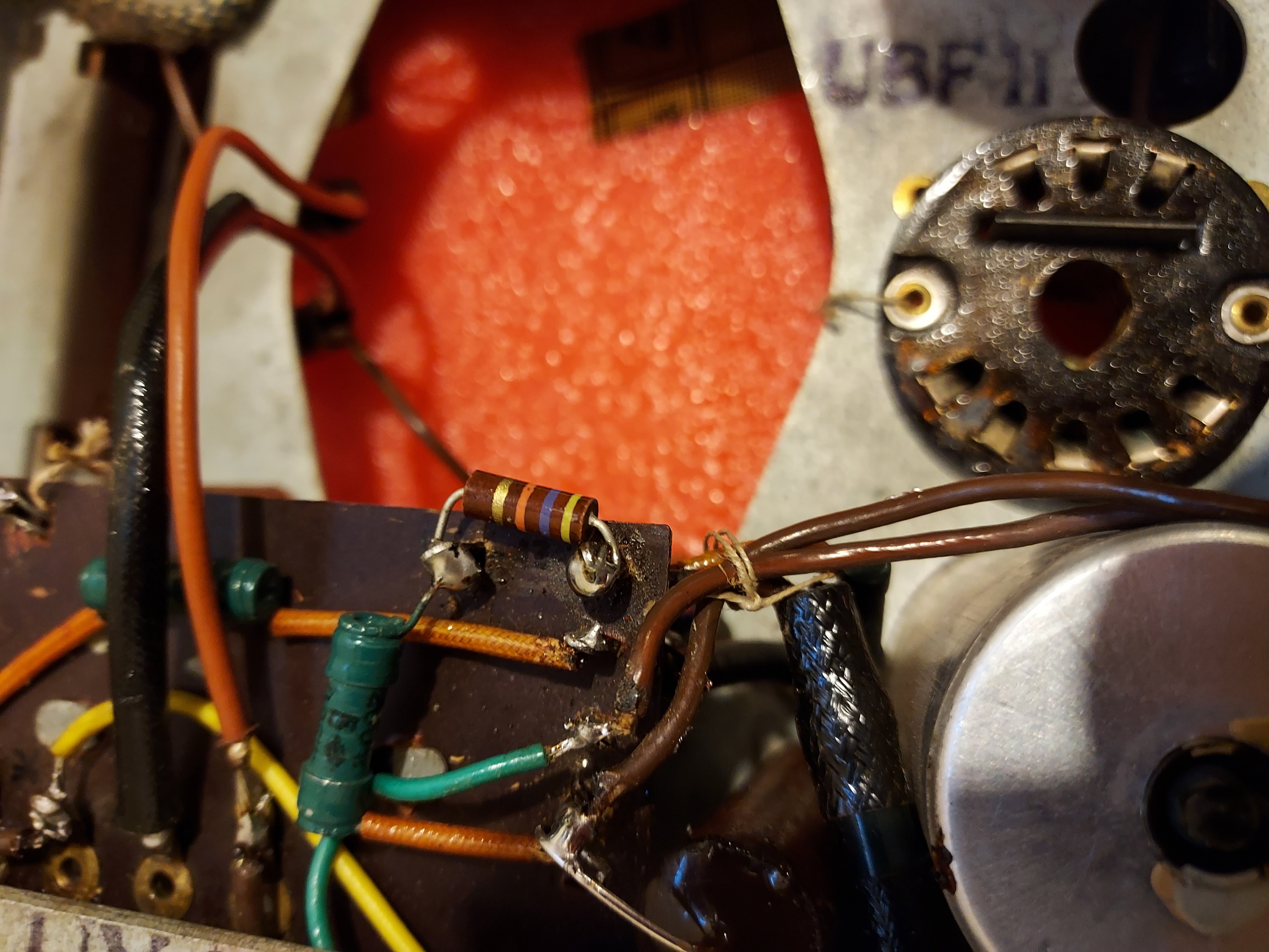
Some other things too. Like that free hanging electrolytic I showed on one of the photos, it was connected one solder post over the one that it was supposed to go to. That is, instead of filtering some plate voltage, it suppressed the feedback that comes with that 0.1uF cap from the speaker to the volume pot circuit. Again, that would not keep the radio from singing, but it is wrong.
I am sure there are variations, but there is not a whole lot of docs on this radio, except maybe in Radio Museum.
PS. Was able to download a sch from Radiomuseum that seems to be closer to mine; at least there is that 2.5nF cap between the plate and the screen grid of the output tube that the other sch does not show.
People who do not drink, do not smoke, do not eat red meat will one day feel really stupid lying there and dying from nothing.
Posts: 16,476
Threads: 573
Joined: Oct 2011
City: Jackson
State, Province, Country: NJ
Slowly but surely. Figured and traced some resistors and caps. The caps get restuffed, one, a 10nF, is not a paper cap, not sure what it is. On the Photo #4 (from the start) it is on the phenolic board right over the grey output tube. But it is exact value, so it is staying.
In the newer sch there are optional parts, shown by dashed line, and some of them are present, and some are not. I possibloy have another 2 or 3 tubulars to stuff, and then the electrolytics. And the tubulars....they are very slim, 5mm, so I need to find slim caps to put inside, else I will have to use yellow caps uncovered.
People who do not drink, do not smoke, do not eat red meat will one day feel really stupid lying there and dying from nothing.
Posts: 16,476
Threads: 573
Joined: Oct 2011
City: Jackson
State, Province, Country: NJ
In a way this radio reminds me of 38-690, in the way they tuck capacitors in hard-to-reach places.
- Our toothbrush will clean teeth in hard-to-reach places.
- But I do not have teeth in hard-to-reach places!
Had t order some caps from AES. I have the needed values, but they are too fat and will not go in the shells of the existing caps.
People who do not drink, do not smoke, do not eat red meat will one day feel really stupid lying there and dying from nothing.
Posts: 5,162
Threads: 273
Joined: Nov 2012
City: Wilsonville
State, Province, Country: OR
Mike, great family story to go with that radio. Don't know if this will help but I have put in some caps that were bigger than the paper tube that they needed to go into. In this case it was a safety XY cap. I slit the tube and pushed it in as far as it would go and then when I installed it in the radio I just made sure the ugly side was down so you could not see it. Turned out looking pretty normal in the end.
[Image: https://www.dropbox.com/s/oosnszmi8cplqq....JPG?raw=1]
Posts: 16,476
Threads: 573
Joined: Oct 2011
City: Jackson
State, Province, Country: NJ
Bob
Would you believe me if I told you I thought of doing exactly that?
But then I thought I needed these values replenished a yway, and found the caps of the size I needed sold in AES. Meantime will restuff the lytics
People who do not drink, do not smoke, do not eat red meat will one day feel really stupid lying there and dying from nothing.
Posts: 16,476
Threads: 573
Joined: Oct 2011
City: Jackson
State, Province, Country: NJ
Time to rebuild the electrolytics.
I am sure there was a reason for the previous guy to add the electrolytics, so I am still going to gut them.
Here's how he did it:
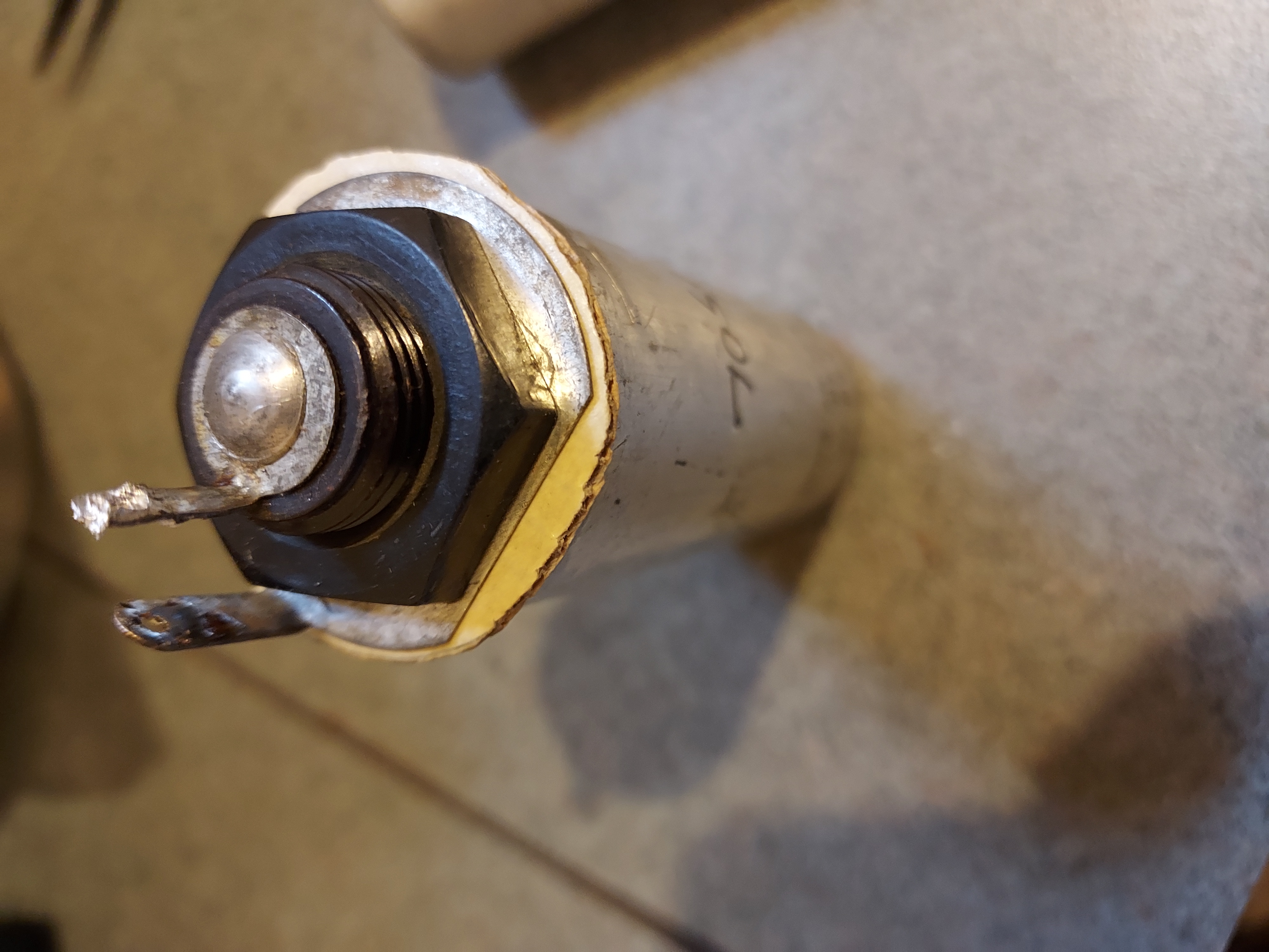
He simply isolated the Neg. ring from the case by a cardboard washer. Smart. And then he used the ring as a solder post.
He also put the notes right on the caps:
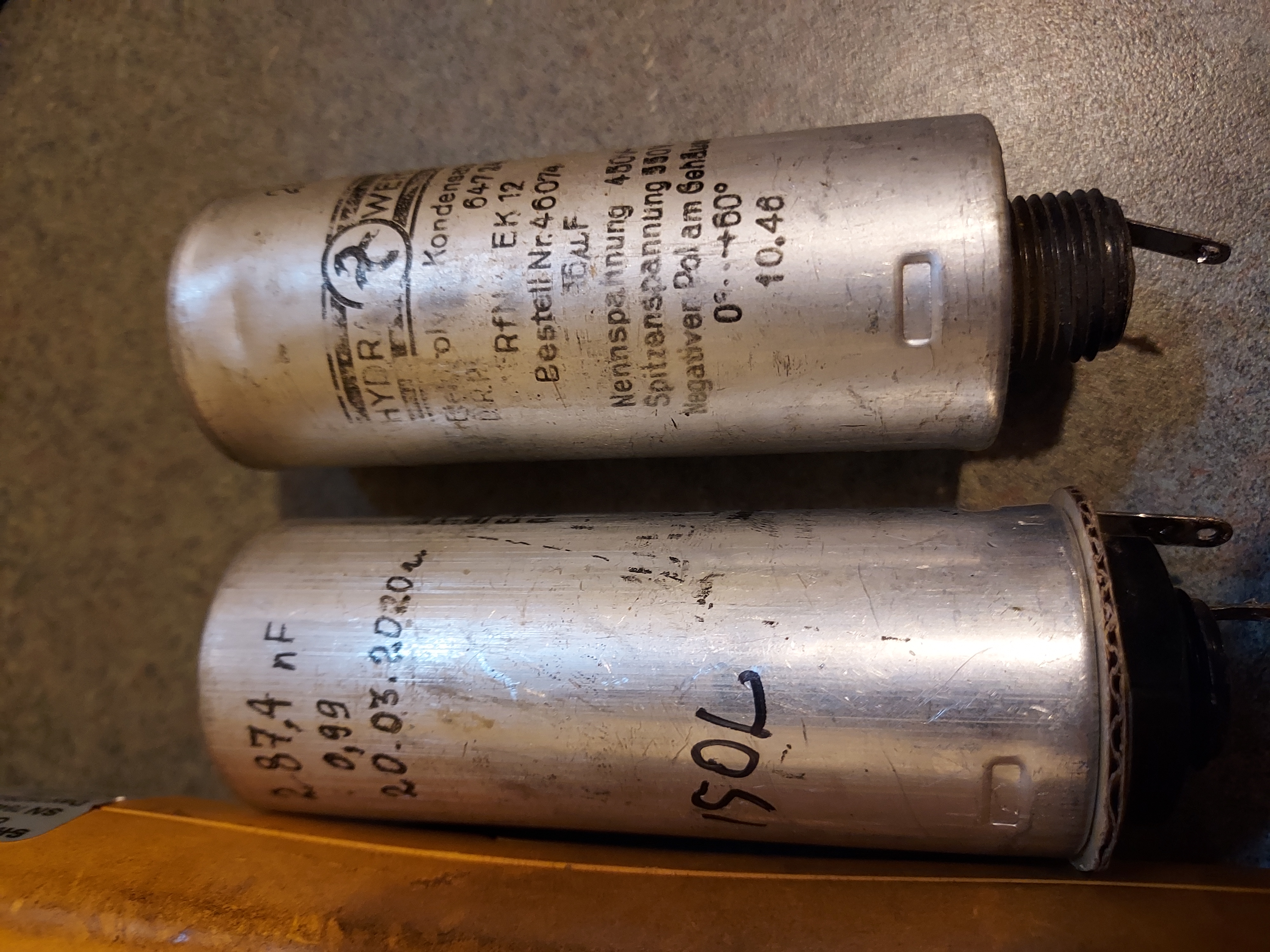
This shows he worked on it mere 3 years ago.
I am not sure why one cap says "287,4 nF" (remember, outside the US the decimal separator is comma, not period).
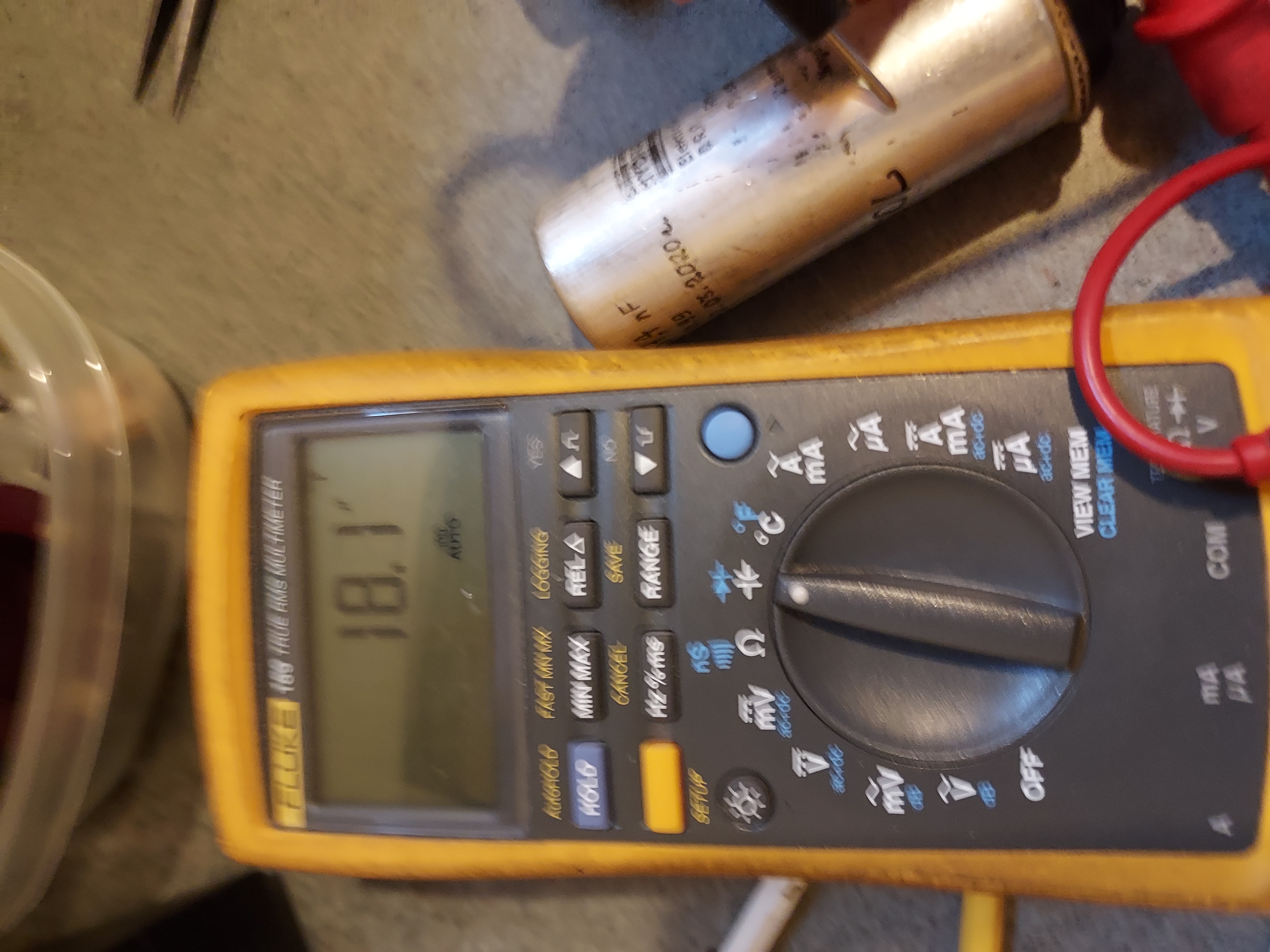
Here's what my measurements are:
The 1st filter cap.
The second
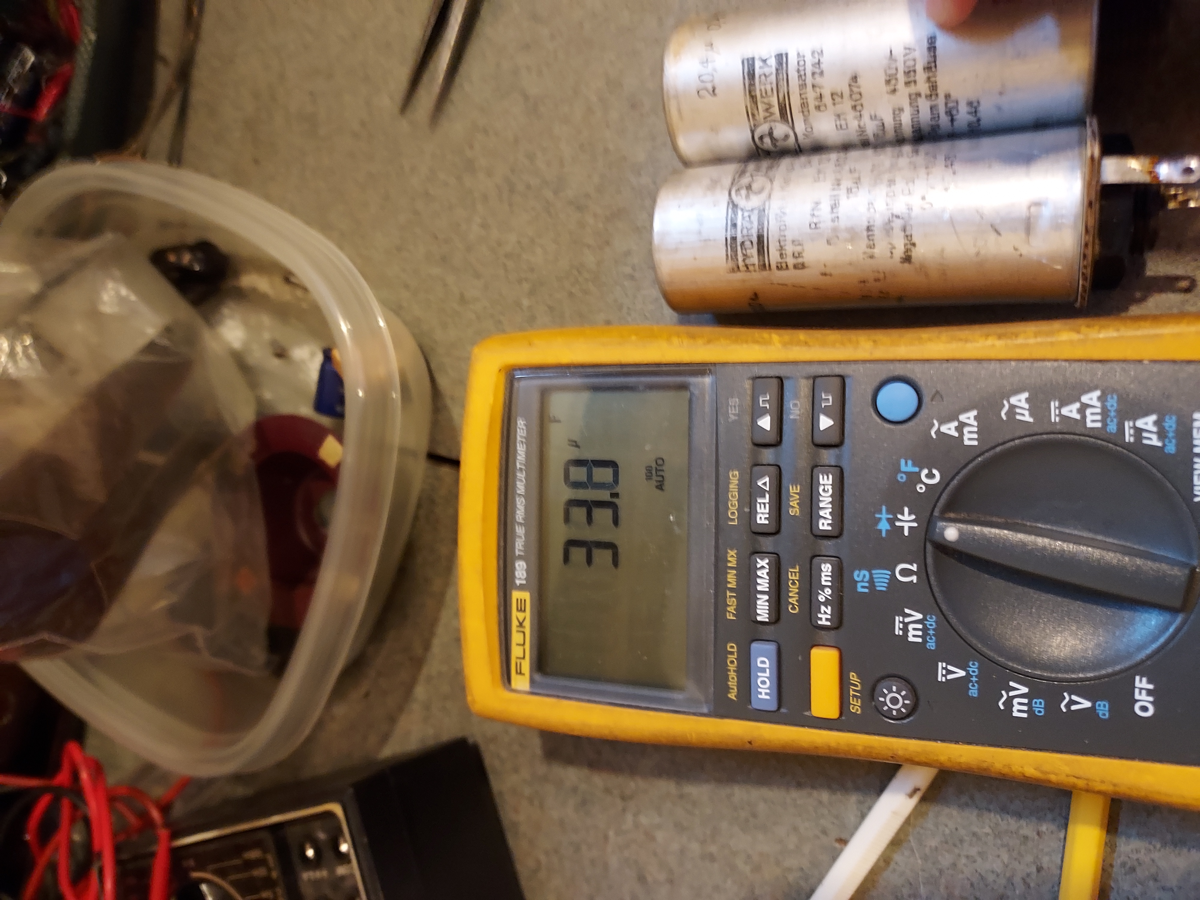
I'd say, this looks like reformable case, but it is easier for me to rebuild and not to think about it anymore.
I am going to use nice Panasonic 33uF 450V caps, two in series, to achieve 16uF (The sch value and the one written on the caps, which are the original ones; I like to keep the 1st cap close to the original value) and then 22uF 450V for the 2nd. All caps have 680mA or so ripple current rating.
People who do not drink, do not smoke, do not eat red meat will one day feel really stupid lying there and dying from nothing.
Posts: 3,148
Threads: 56
Joined: Apr 2011
City: Lexington, KY
Interesting radio Mike and a great family story to go along with it.
We used to market a 'low cost' small CT Scanner that used a small Telefunken x-ray tube. I installed one in a small truck for a crazy doc in Louisville years ago. Instead of buying the proper chiller for the x-ray tube he modified a water fountain  . They could only do about 10 scans before the temperature sensor shut down the high voltage. He ran that darn thing all over Kentucky and Indiana. One time the driver figured out how to jumper the temperature sensor and the tube got so hot it melted the brass insert and almost dripped on a patients face  . I was delighted when the driver rolled the truck and he didn't install another one. He eventually lost his license for developing all his x-ray films in the local VA hospital film processors.
John KK4ZLF
Lexington, KY
"illegitimis non carborundum"
(This post was last modified: 06-04-2023, 08:41 AM by Eliot Ness.)
Posts: 16,476
Threads: 573
Joined: Oct 2011
City: Jackson
State, Province, Country: NJ
John,
Deutsche Ingenieurskunst. Es ist gut. Das stimmt!

As for bypassing temp sensors, Russian guys, back in Russia, bypassed the temp sensor in sauna. 90 degrees C it gave was not enough, and so it was bypassed to get 120C (100C is the water boiling point).
I went to it several times. Great feeling. I was 18 and had no know cardiovascular problems at the time.
People who do not drink, do not smoke, do not eat red meat will one day feel really stupid lying there and dying from nothing.
Posts: 16,476
Threads: 573
Joined: Oct 2011
City: Jackson
State, Province, Country: NJ
Meantime I soaked the caps' shells in vinegar overnight; they came out all squeaky clean inside, and now I am baking them at 200C (don't want to melt anything) in my old toaster oven that was replaced by a Ninja super-duper one, at my wife's wish, and I benefitted from it by having my own baking oven.
An hour or so, and then I will drill them and prep for restuffing.
People who do not drink, do not smoke, do not eat red meat will one day feel really stupid lying there and dying from nothing.
Posts: 16,476
Threads: 573
Joined: Oct 2011
City: Jackson
State, Province, Country: NJ
All the caps have been restuffed and all byt the 'lytics have been placed.
AES listed the size of 4.7nF cap wrong, 0.18" i/o 0.27", and so I found the slimmest 4.7nF I had and then drilled the shell to gain that extra 1/64" to push it inside.
Will place the 'lytics tomorrow.
People who do not drink, do not smoke, do not eat red meat will one day feel really stupid lying there and dying from nothing.
Posts: 16,476
Threads: 573
Joined: Oct 2011
City: Jackson
State, Province, Country: NJ
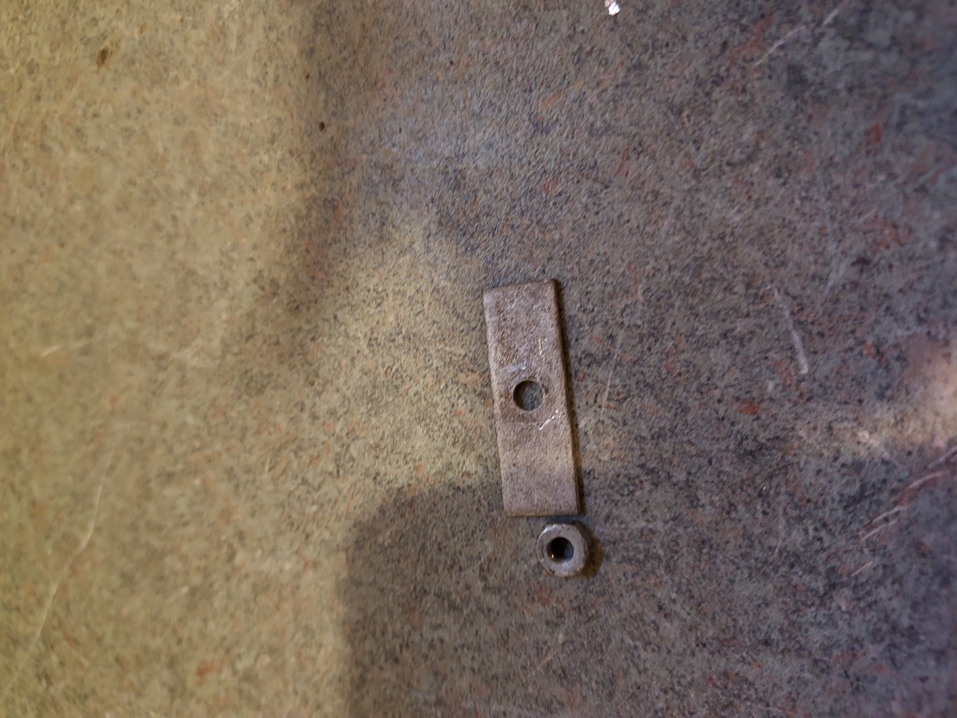
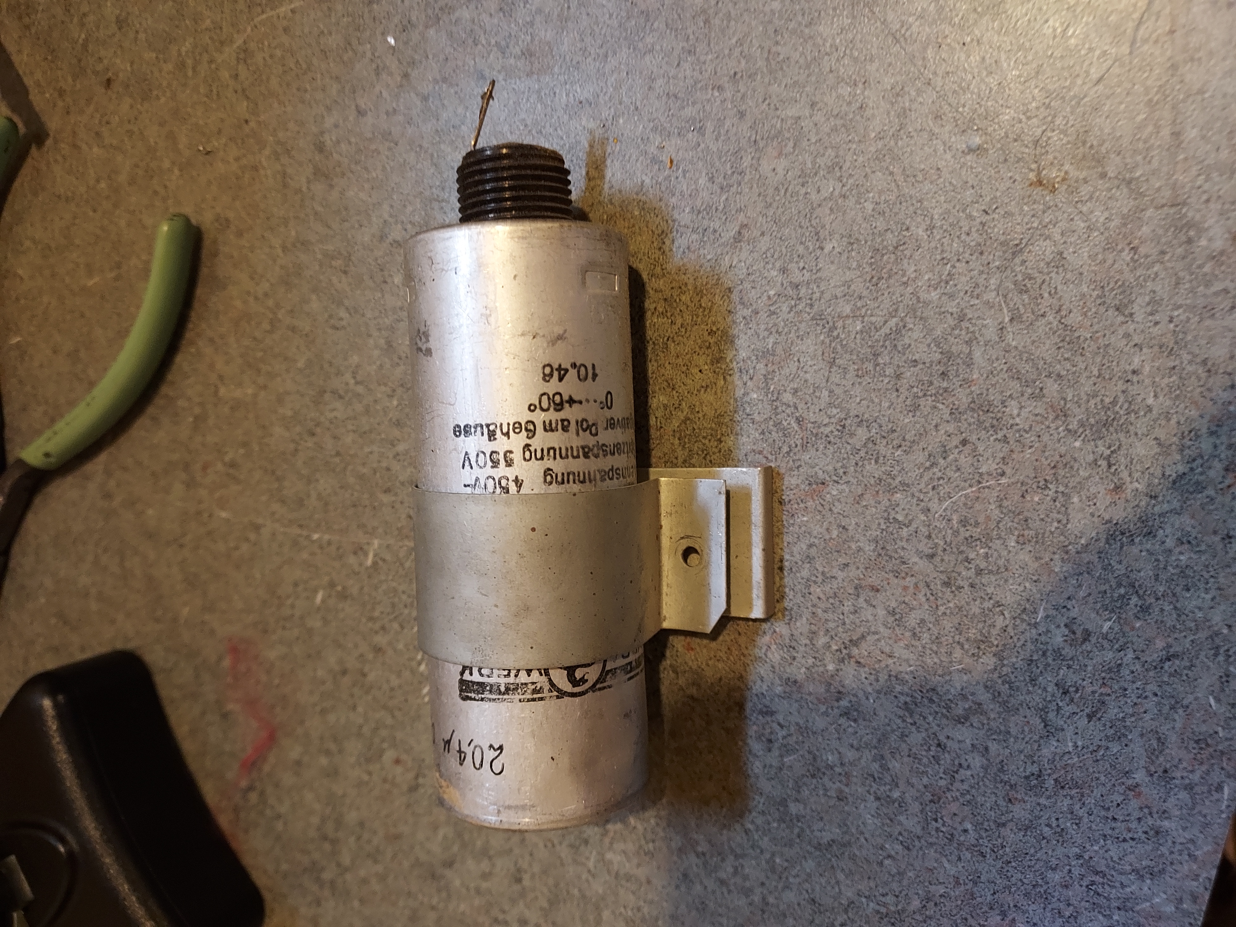
The cap clamp.
Struggling with putting them back.
The caps are as seen below, are mounted under the dial (and all the pointer moving gear), plus right next to the tuning cap.
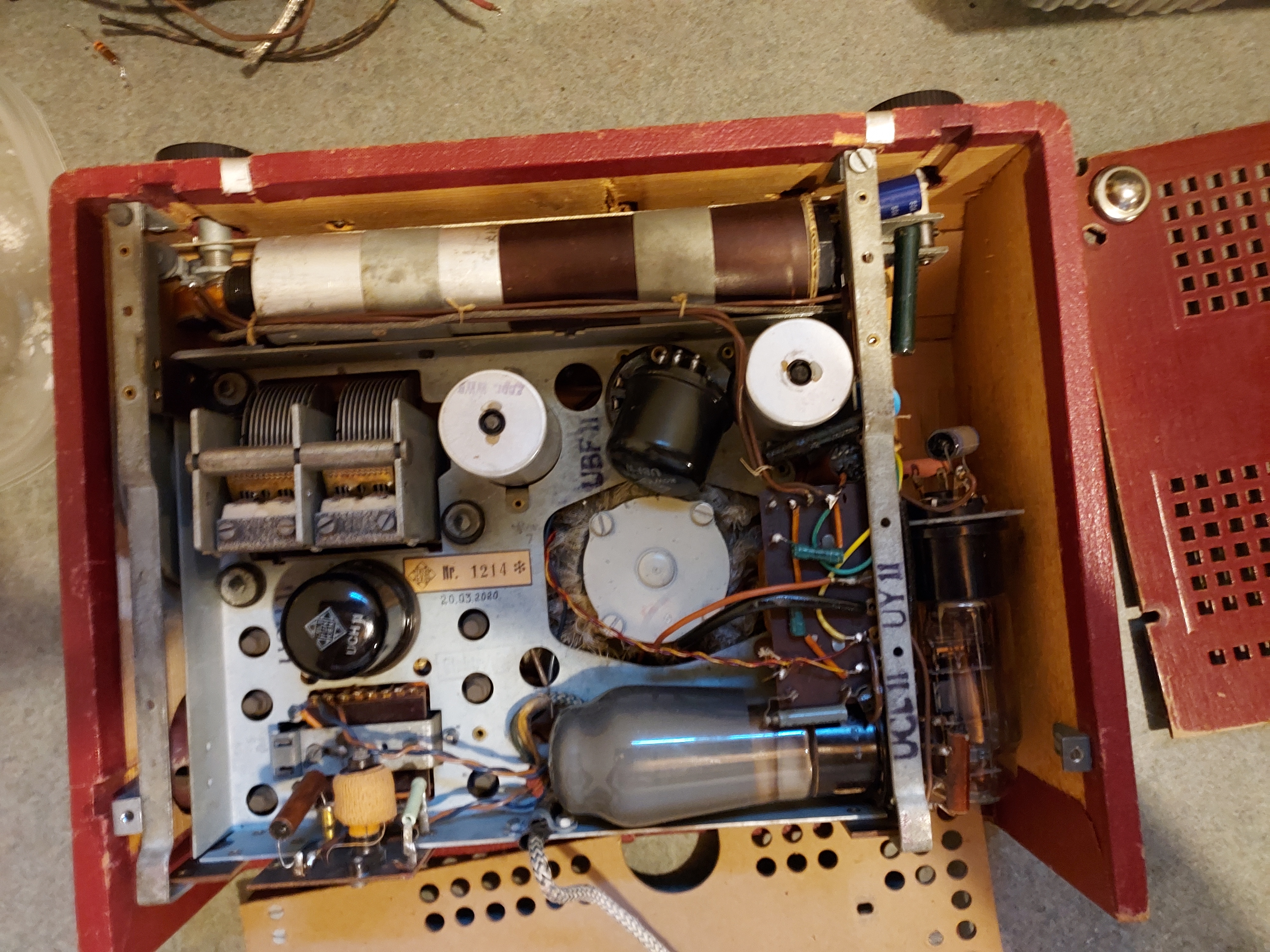
This requires being gentle while putting the caps back, in order nopt to scratch, tear or bend anything. Which means using one finger holding the screw that has to go through the clamp. But the clamp is very tight around the cap, and has the outer part forming acute angle which I have to push in to align the two holes through which the screw has to go through. And whem fully pushed in, I still have some 40-60 mils overlapping of the holes. I was able to put the first (insulated, in brown plastic wrap, shown at the bottom of the photo) cap in, but that was further from the tuning cap, and with the top one, I am afraid to push to hard, which I have to do with large flat scredriver that pushes its blade right against that crease (the acute angle). You could see the screw, a black bum at the back of the cap, between the bottom of the tuning cap and an IF can. I have to hold that one with one finger, and not to move much lest I bend the tuning cap's vanes. And then when successful, I have to hold it from coming apart, put the bar on the screw and then put the nut and try to rotate it with one finger (the nut will sit inside that crease which makes the access....tight).
Yesterday after 20 minutes of trying I relented and will continue tonight.
People who do not drink, do not smoke, do not eat red meat will one day feel really stupid lying there and dying from nothing.
Posts: 622
Threads: 21
Joined: Nov 2014
City: Svalyava
State, Province, Country: Ukraine Transkarpati
Quote:...Yesterday after 20 minutes of trying I relented and will continue tonight. ...
This is German radio, sir.  I warned. I ran for Popcorn 
Old Tube Radio Online Museum / Музей ретро радіо
https://www.youtube.com/user/RadioSvit?d...lymer=true
Sincerely Peter
З повагою Петро
Posts: 1,119
Threads: 44
Joined: Feb 2015
City: Roseville, MN
Nice move Peter.
Mike, now's the time to wonder why the designer wasn't required to do this before finalizing the plans. (Do parts really have to be replaced?)
Users browsing this thread: 2 Guest(s)
|
|
Recent Posts
|
|
Need to purchase some accessories for restoration of my Old Philco Radio
|
| Here is a list of resources found in our online library that you might find useful. Mike's Gobs of Knobs email addres...klondike98 — 01:46 PM |
|
First Radio restoration
|
| Hi Tubeman,
Welcome to the Philco Phorum. Phamily Phriendly Pfun with Phine Pholks Phull of Philco Phacts. (See a p...MrFixr55 — 12:33 PM |
|
First Radio restoration
|
| You could post in the WANTED ADs section here on the Phorum and see if anyone has an RF generator that they want to sell...klondike98 — 11:55 AM |
|
Zenith H725
|
| Good ideas, thank you Arrange and Rich. I have the adhesive aluminum foil already and can try that immediately.
More ...EdHolland — 10:18 AM |
|
Graphics for majestic 1050 dial glass.
|
| Murf;
I found this thread on the ARF, the first photo has a pretty good view of the dial glass.
Regards
ArranArran — 01:12 AM |
|
Zenith H725
|
| hello Ed,
how about that speacial tape used for ducting it's like foil or how about thin piece of
aluminum roof flash...radiorich — 12:19 AM |
|
Zenith H725
|
| Ed;
One material that I have seen, but never tried for this was material for making exhaust gaskets, it's similar to ...Arran — 11:42 PM |
|
Zenith H725
|
| I just remembered, I have some hi temp silicone rubber material which could do the trick. Or a piece of FR4 laminate. Th...EdHolland — 08:39 PM |
|
Zenith H725
|
| The PSU filter cap arrived today (thank you USPS!) so I will work on that later.
Meanwhile, I have the dial, speaker...EdHolland — 06:42 PM |
|
Philco 610B oscillator wiring
|
| Thanks Terry. After checking my notes I think I recorded about -10v at the 6A7 G4/control grid. The screen grid (G3 &...Tubester — 05:59 PM |
|
Who's Online
|
| There are currently no members online. |

|
 
|


![[-] [-]](https://philcoradio.com/phorum/images/bootbb/collapse.png)


