Telefunken T6445GWK restoration
Posts: 15,818
Threads: 554
Joined: Oct 2011
City: Jackson, NJ
Rod
the designer is likely has been dead and buried for a lomng time. So if I wanted to say "sehr schleht, Herr Designer!", I'd have to dig deep 
It is what it is. Judging by the previous repairperson paralleling the caps, these (despite not having become dry) obviously developed some problems. So I have to puit it back together now.
I will see if a beer before the operation helps.
People who do not drink, do not smoke, do not eat red meat will one day feel really stupid lying there and dying from nothing.
Posts: 15,818
Threads: 554
Joined: Oct 2011
City: Jackson, NJ
OK, the cap is in: after several futile attempts I simply inverted the screw and put it from the front to the back, placing the nut where the screwhead used to be. This way I was able to put the screw in the clamp BEFORE placing it in (and even that was a bit onerous), and then I placed the whole thing with the cap in, adjusted the cap and tightened the screw.
The radio is assembled.
But. Now I have another question. I do not see the power switch anywhere. And I cannot figure the autotransformer out.
I actually need to ask Peter, how he was listening to it - Peter, did you use any switch to turn it on, or it was always on?
Or (a guess) is the power switch coupled with the band switch and turns it off when none of the bands are selected (it has 3 bands but 4 positions) ?
The problem is, this being an AC/DC radio, the plug always rings open unless the tubes are in.
I cannot turn it on as it is set for 220VAC.
I do not see not only the power switch (which I think is coupled with band switch) but also I do not see the voltage setting switch. I even doubt there is one. And I need to set it for 120VAC.
People who do not drink, do not smoke, do not eat red meat will one day feel really stupid lying there and dying from nothing.
Posts: 1,599
Threads: 101
Joined: May 2008
City: Omak
State, Province, Country: WA
Hello mike,
So far you have done some really nice work on this set !
Sincerely Richard
Posts: 15,818
Threads: 554
Joined: Oct 2011
City: Jackson, NJ
II am sure I could fire it up from my booster Variac that makes 220V out of 120V. But I do not want to do it. I want it switched to 120V.
People who do not drink, do not smoke, do not eat red meat will one day feel really stupid lying there and dying from nothing.
Posts: 572
Threads: 20
Joined: Nov 2014
City: Svalyava Transkarpatia
State, Province, Country: Ukraine
Quote:Or (a guess) is the power switch coupled with the band switch and turns it off when none of the bands are selected (it has 3 bands but 4 positions) ?
Yes, this is a correct assumption. That's right, the power switch is combined with the range switch.
Why is there no voltage switch? I suspect that the previous master simplified the scheme and simply threw out all the details that had to do with the voltage of 120 volts. But since this is a transformerless version, there could be only a few additional resistors. I think that you can easily turn it back and even simplify the scheme even more - throw away everything that is related to the voltage of 220 volts. You don't need it. 
Old Tube Radio Online Museum / Музей ретро радіо
https://www.youtube.com/user/RadioSvit?d...lymer=true
Sincerely Peter
З повагою Петро
(This post was last modified: 06-09-2023, 05:10 AM by RadioSvit.)
Posts: 15,818
Threads: 554
Joined: Oct 2011
City: Jackson, NJ
No, this does have the auto transformer. It is not used when it is 220V, as one wire simply goes past it. With 120V it is engaged, so both wires go to it and the voltage is derived from the winding's ends, boosted to 220V.
People who do not drink, do not smoke, do not eat red meat will one day feel really stupid lying there and dying from nothing.
Posts: 572
Threads: 20
Joined: Nov 2014
City: Svalyava Transkarpatia
State, Province, Country: Ukraine
I see that on all diagrams this transformer is marked as an option, not standard equipment. Do you see this autotransformer on the chassis of the radio, or do you only see it on the diagram?
Old Tube Radio Online Museum / Музей ретро радіо
https://www.youtube.com/user/RadioSvit?d...lymer=true
Sincerely Peter
З повагою Петро
Posts: 15,818
Threads: 554
Joined: Oct 2011
City: Jackson, NJ
OK, I took another look.
What I thought was a transformer (it did look like one, the contact panel and something resembling the core it was mount on) is a simple contact panel on the very power switch we wre talking about.
So....it is 220AC/DC only version.
Removing the Resistors will not help as they are only for filaments, and the B+ is directly rectified from 220V.
OK, I will have to power it up with a Variac only.
But. this is what I can possibly do. They used half-wave rectifier. I could use full wave and get higher B+. And use a capacitor to drop the volta for the filament (or adjust the resistor).
People who do not drink, do not smoke, do not eat red meat will one day feel really stupid lying there and dying from nothing.
(This post was last modified: 06-09-2023, 05:23 PM by morzh.)
Posts: 15,818
Threads: 554
Joined: Oct 2011
City: Jackson, NJ
OK, no such luck.
Here's why. The tubes a 100mA and the summary of the volts is 20+20+50+60 is 150V. Which makes 120V insufficient. It will probably work, but not well, as the filament power will drop almost twice (150/110 square) or a bit les than twice but still a lot at 120V.
The resistances are thereby 1.5K plus 700 Ohm is 2.2K, which makes exactly 100mA at 220V.
Without the autotransformer I cannot bring the voltage up to 150V for the filaments.
I of course could do this: use 50+60 and a small resistance, and parallel that with 20+20 and a capacitor. But this is a lot of rerouting and I do not like rerouting things like it.
Thinking....thinking.....
I need overall impedance of 1,200 Ohm. The tubes are 400 Ohms together. I need 1.13K equiv. cap in series with two tubes with 20V filaments. This makes for 2.34uF cap.
People who do not drink, do not smoke, do not eat red meat will one day feel really stupid lying there and dying from nothing.
(This post was last modified: 06-09-2023, 06:30 PM by morzh.)
Posts: 572
Threads: 20
Joined: Nov 2014
City: Svalyava Transkarpatia
State, Province, Country: Ukraine
Michael. Or maybe you don't need to invent a bicycle.... Make a small transformer power supply unit for 220 volts AC with a step-up transformer and you will have an additional 220 volt network for European radios. Well, I made myself a 110 volt network for American radios. This will solve similar problems for the future.
PS. In addition, pay attention that at a voltage of less than 150 volts, the voltage will be very low not only for the filaments of the radio lamps, but also the anode voltage will drop significantly and the radio will not work well because the sensitivity and output power will drop, and distortions may also appear in the sound amplifier. Make a 220 volt power supply unit, but a transformer one.
Old Tube Radio Online Museum / Музей ретро радіо
https://www.youtube.com/user/RadioSvit?d...lymer=true
Sincerely Peter
З повагою Петро
(This post was last modified: 06-09-2023, 06:45 PM by RadioSvit.)
Posts: 15,818
Threads: 554
Joined: Oct 2011
City: Jackson, NJ
I do not need to make it, I have it.
They bought a smaller than needed one at workm and then they decided to get rid of it, and I appropriated it.
And good thing is, it is a transformer type, not a converter.
We needed it to test 220V device we made for Europe.
A 200W set, ideal for a small radio. Brand-spanking-nu!
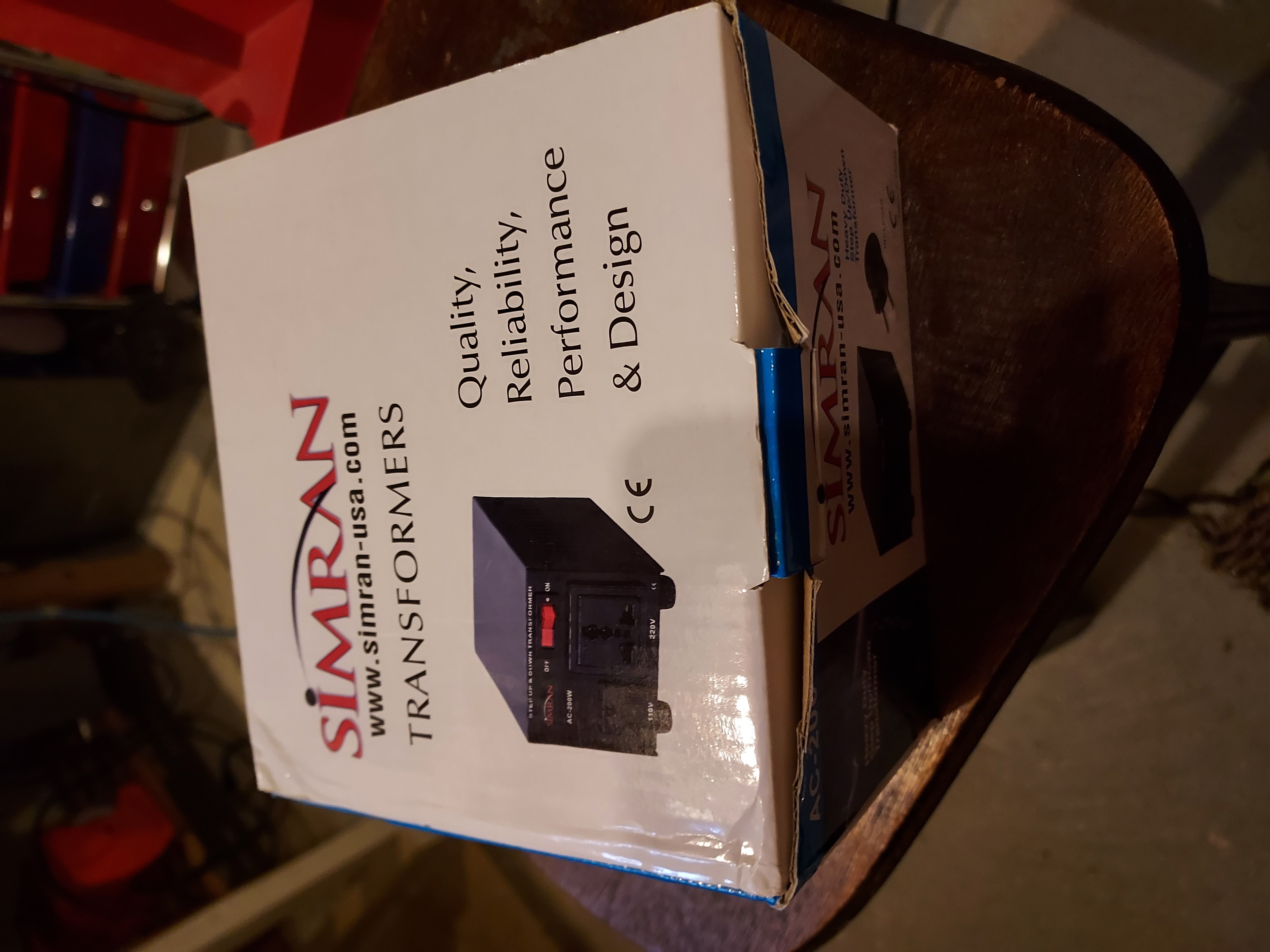
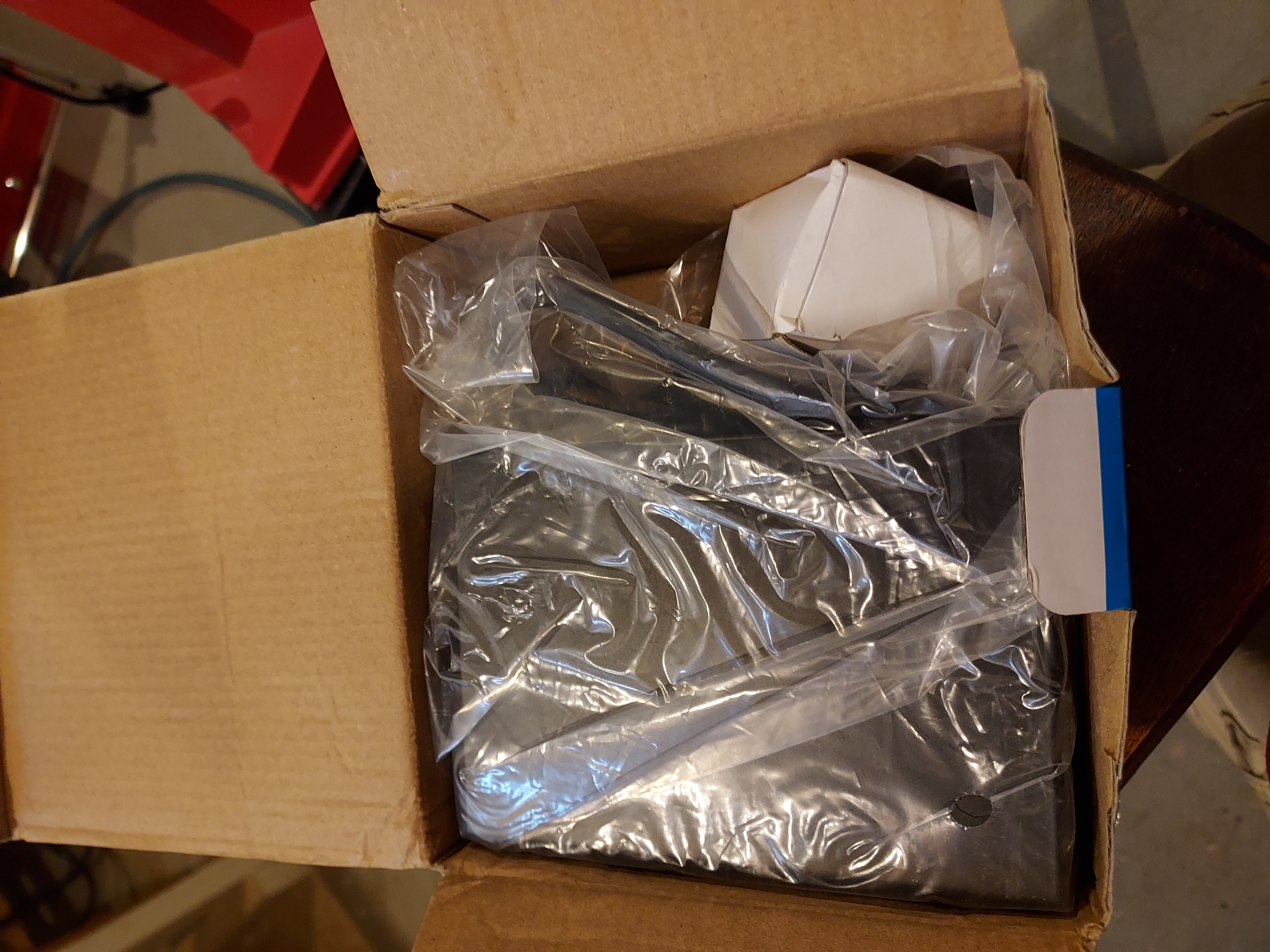
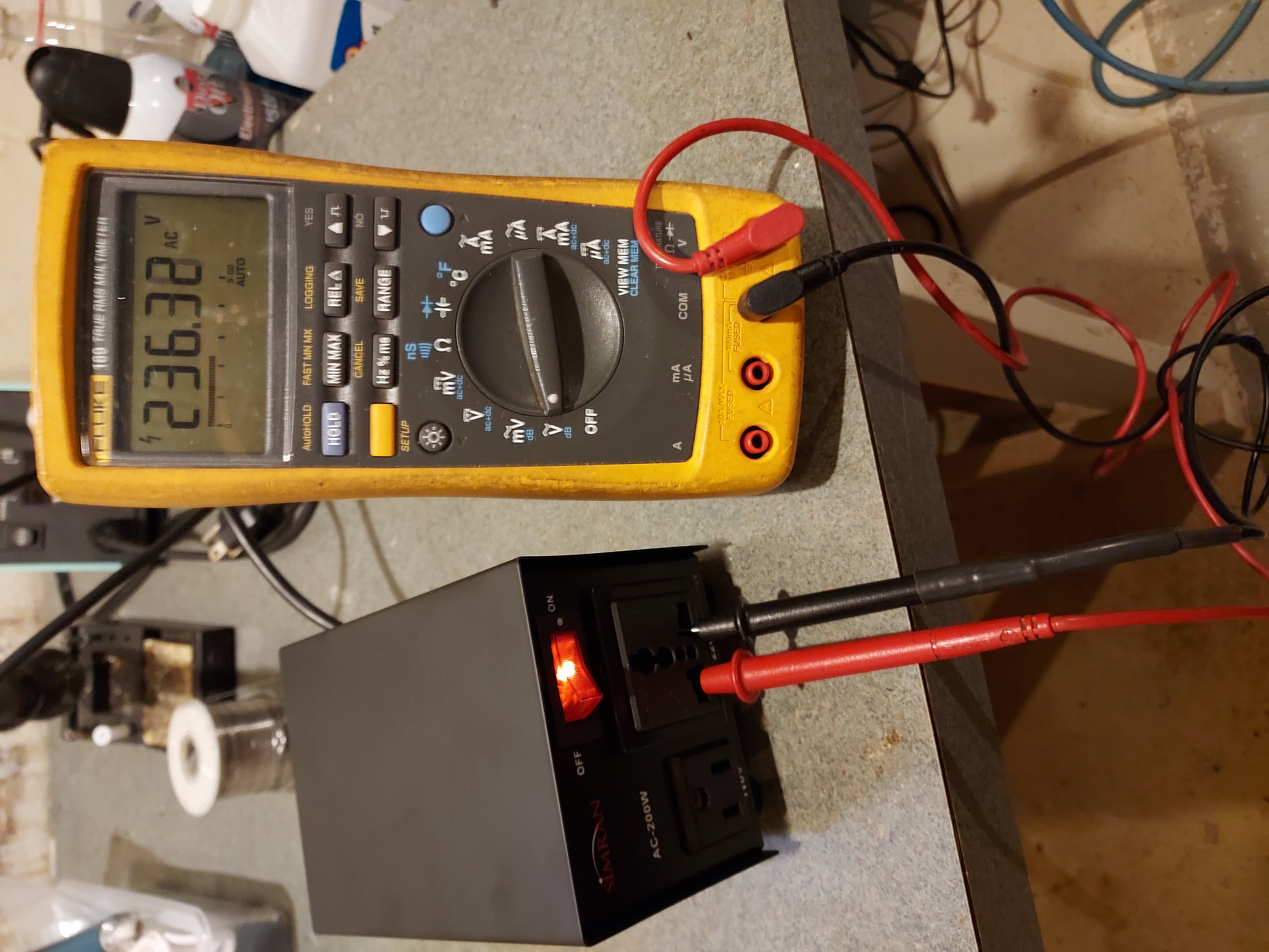
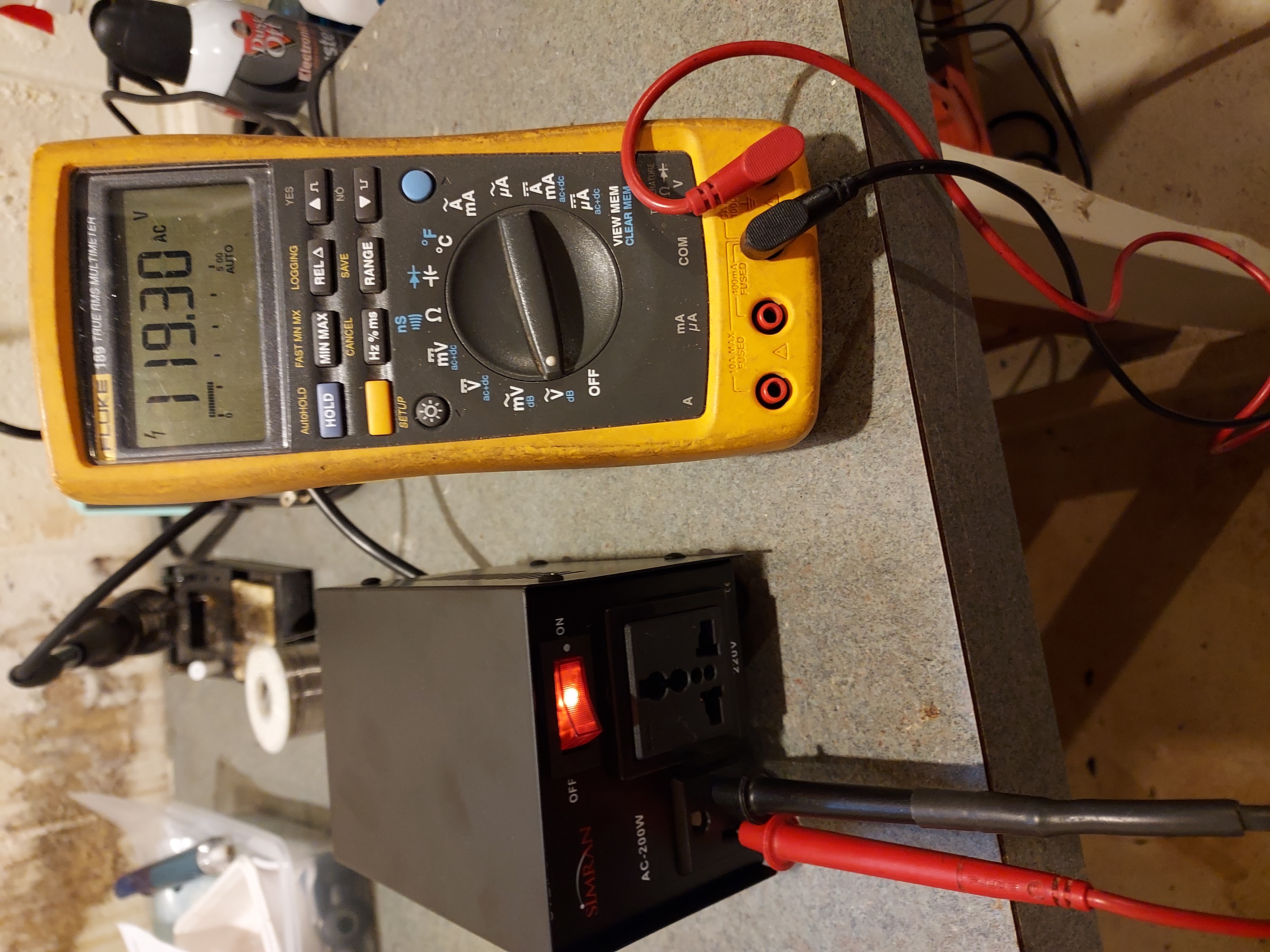
I both steps up and steps down. I could flip the switch in the back and it gives me 60V and 120V respectively from my outlet.
People who do not drink, do not smoke, do not eat red meat will one day feel really stupid lying there and dying from nothing.
(This post was last modified: 06-09-2023, 06:57 PM by morzh.)
Posts: 4,705
Threads: 51
Joined: Sep 2008
City: Sandwick, BC, CA
Mike;
From what I have read elsewhere those short metal tubes where called "stahl" or steel tubes, and were developed, and originally produced by Telefunken in 1938. The first time I saw some was in a war time set another collector had, they looked like oversized 6H6 tubes, and from what I can tell they carried on making them in Germany, and Poland well into the 1950s (or later), maybe some other Warsaw pact countries as well. Do they all have eight pin bases in that set? A really strange pinout, five on one side and three on the other, I would guess that the three pin side is for the tube heater plus the cathode, but since the base has a key why bother?
Regarding the line voltage, I was contemplating buying a Bush radio, and whilst the tube heaters only added up to 120 volts the B+ was as high as 180 vdc. In that case I had the idea of using a voltage doubler to raise the B+ but I never got the radio to find out if it would work
Regards
Arran
Posts: 15,818
Threads: 554
Joined: Oct 2011
City: Jackson, NJ
Arran
Yep, the 8-pin keyed socket. All the pinouts are eaisly seen in Radiomuseum's pages.
I won't be able to test them but will presume tthey are working tubes as Peter has the video of the set working. One tube was out of socket when it arrived but I hope it did not bounce much as it was immediately glued to the speaker's magnet (Stahl !!! High iron content.)
The doubler takes two diodes and so creating a tube one is out of the question.
I have already written about trying to use bridge rectifier, as, again, I do not have space for an extra capacitor either (it takes two caps and two diodes to double in Greinacher circuit). The bridge will effectively double the DC level (2/3 peak vs 1/3 peak) vs half-wave and the RMS is 40% higher also.
And the caps is probably not a bad idea either, as even in the original circuit with 220VAC there will be at least 7W dissipation to ballast the 220V to the needed 150V (they have 700 ohm resistor at 100mA).
I will use that Simran of mine together with the Variac to achieve 220V (I have 240V out). Though I see additional, not accounted in the sch, 70 Ohm resistor. The big green one, it is on the photos. I wonder if it was put there for that very reason: the voltage in Europe is also a bit higher than 220V.
People who do not drink, do not smoke, do not eat red meat will one day feel really stupid lying there and dying from nothing.
Posts: 15,818
Threads: 554
Joined: Oct 2011
City: Jackson, NJ
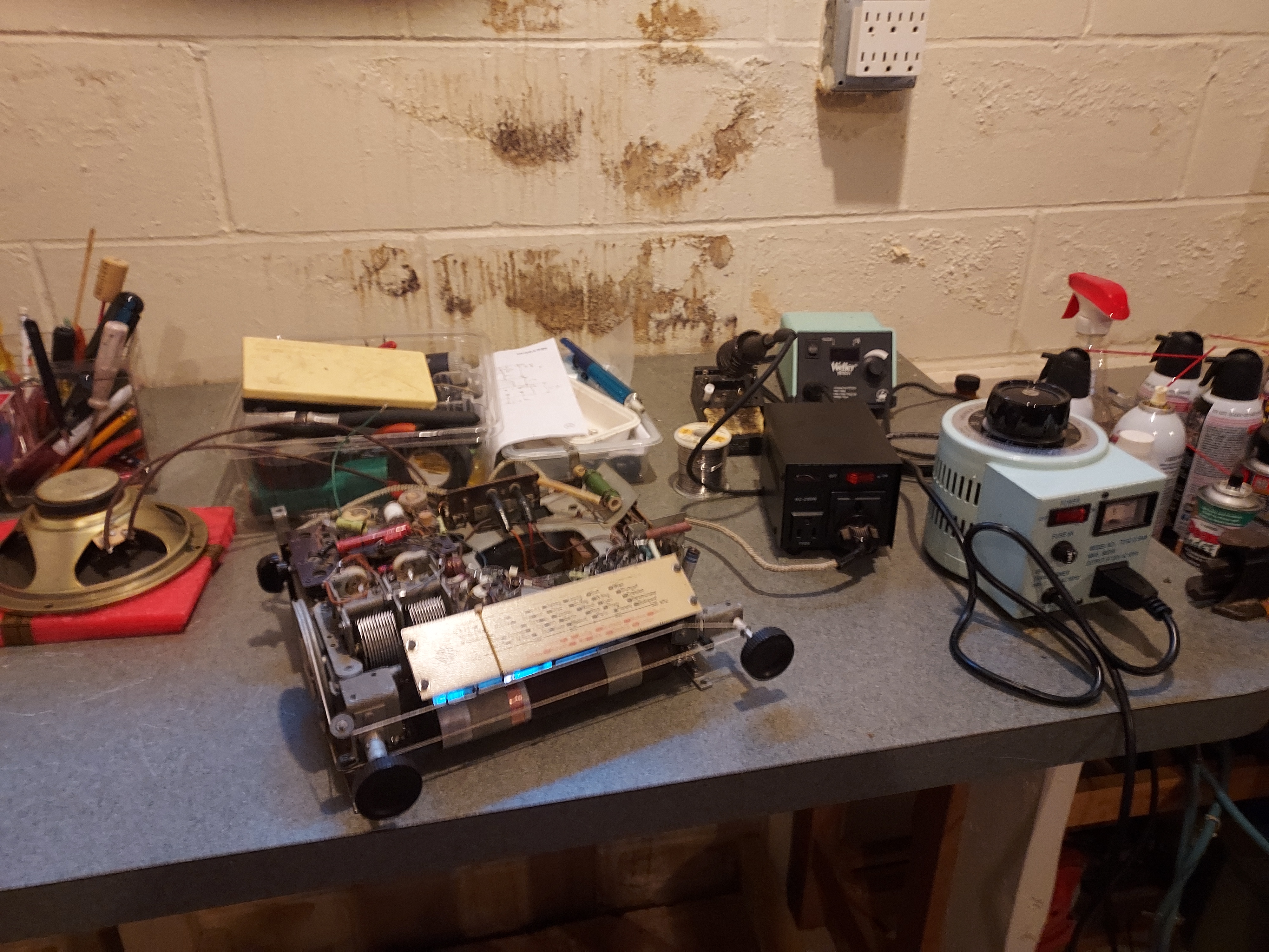
OK. I put the Simtran to VARIAC, set the latter to 110 VAC, connected an 8 Ohm speaker I have for tests, and plugged it in. The DC rose nicely, and the radio played.
I have a video, have to see if I want to put it to Youtube, considering.....I made the music clip less than 5 seconds.
I put less than 1' long wire to the antenna, to make the reception a tad better, as I am in the basement.
Now I need to align it. I have something I downloaded from Radiomuseum, in German. I hope this is alignment, but can't be sure before I read and translate it.
People who do not drink, do not smoke, do not eat red meat will one day feel really stupid lying there and dying from nothing.
Posts: 15,818
Threads: 554
Joined: Oct 2011
City: Jackson, NJ
 06-10-2023, 01:53 PM
Made a short video. Let's see if Youtube is Ok with it.
[Video: https://www.youtube.com/watch?v=7ag9htwDs4Q]
People who do not drink, do not smoke, do not eat red meat will one day feel really stupid lying there and dying from nothing.
Users browsing this thread: 3 Guest(s)
|
|
Recent Posts
|
|
Philco 42-1008 conversion kit
|
| Interesting. I haven't seen that before.klondike98 — 07:02 PM |
|
12' Philco
|
| Yes I had looked for it on the web as well some time back and could not find it. I was glad to see it turned up in Ron'...klondike98 — 06:59 PM |
|
Shadow Meter Bulb
|
| Now if you had a set with a tuning light then the bulb type is important to the circuit, some sets used those prior to t...Arran — 04:58 PM |
|
Shadow Meter Bulb
|
| Ok. Thanks for the correction.RossH — 03:09 PM |
|
Model 28L
|
| For 28 you will probably need to buy a Hammond 125CSE. Or any of the series of the power you need, with SE suffix. Then ...morzh — 02:09 PM |
|
37-60 revision 6
|
| I am restoring a Philco 37-60 and it shows run 6 they removed the ground from G3 of the 6K7G and put the G3 to -2.5v for...bobbyd1200 — 01:01 PM |
|
Shadow Meter Bulb
|
| Mike is correct on the bulb connection, two separate circuits. I found that by rotating the bulb and sliding it forward ...RodB — 12:19 PM |
|
Hickok AC51 tube tester
|
| Cleaned ann contacts, switches and sockets, works great now.martinj — 11:32 AM |
|
Model 28L
|
| Hello,
I'm restoring a Philco 28L and the output transformer is open. Part number of the transformer is 32-7020.
Can...HORSTE — 10:32 AM |
|
Philco 42-1008 conversion kit
|
| I read about a kit to convert the variable speed changer in the Philco 42-1008 into a single speed unit. That would rem...alangard — 09:30 PM |
|
Who's Online
|
There are currently 8058 online users. [Complete List]
» 1 Member(s) | 8057 Guest(s)
|
|
|

|
 
|


![[-] [-]](https://philcoradio.com/phorum/images/bootbb/collapse.png)


