Telefunken T6445GWK restoration
Posts: 4,950
Threads: 54
Joined: Sep 2008
City: Sandwick, BC, CA
RadioSvit Wrote:Arran, this type of German radio lamps has another slang name - "helmets". From the extraordinary similarity with the German helmets of the Second World War. And you would probably be very surprised if you saw the structure of the armature of these radio lamps - it is not placed vertically, but horizontally.  That is, the filament, cathode, grid and anode are in a horizontal position, not in a vertical position! As it was in radio lamps at the beginning of the 20s That is, the filament, cathode, grid and anode are in a horizontal position, not in a vertical position! As it was in radio lamps at the beginning of the 20s 
Peter;
I could see one adopting a slang term like that for those tubes, we typically call those German helmets "Sergeant Schultz" helmets, or "Coal Scuttle" helmets. They are a pretty decent design for protecting your head, though very heavy compared to a British or Canadian "Tommy Hat" style helmet. They were popular in use as motorcycle helmets at one time, though now they make lighter, and safer replicas out of fiberglass, which have padding in them.
I forgot about the internal structure of those tubes, I think that I read about that elsewhere. It was rather retrograde, the only tube that I have personally own with that sort of arrangement was a Myers tube, which was a triode intended for D.C operation, that produced in Canada in the early to mid 1920s. I wonder if the stahl tubes have more problems with shorts between the elements, anode to grid, heater to cathode, etc. ? The horizontal structure would explain the pin arrangement, the heater, and cathode connections would come out of one end, the grid and anode connections out of the other. The footprint of the socket seems wasteful, one would think that they would make use of the larger diameter to use with multi section tubes, by adding extra pins, but apparently they did not. I think that the Soviet electronics industry was more sensible in adopting octal based tubes, and later the all glass 7 and 9 pin ones ( i think they had lock in tubes as well did they not?)
Regards
Arran
Posts: 664
Threads: 23
Joined: Nov 2014
City: Svalyava. Transkarpatia
State, Province, Country: Ukraine
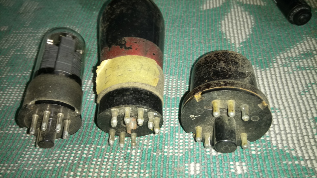
Yes Arran. The socket area of German radio tubes is still larger than that of octal radio tubes. Here is a photo for comparison.
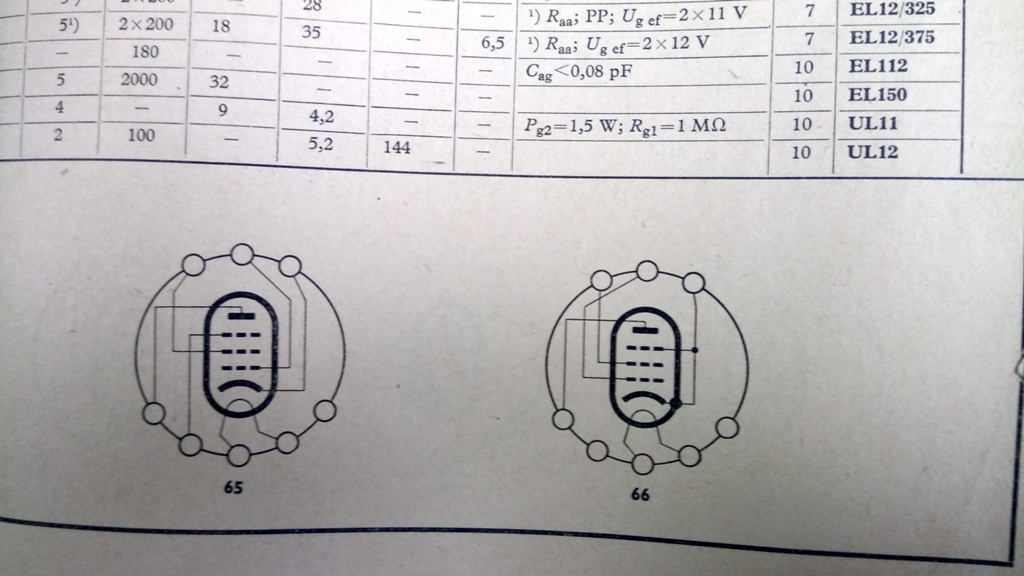
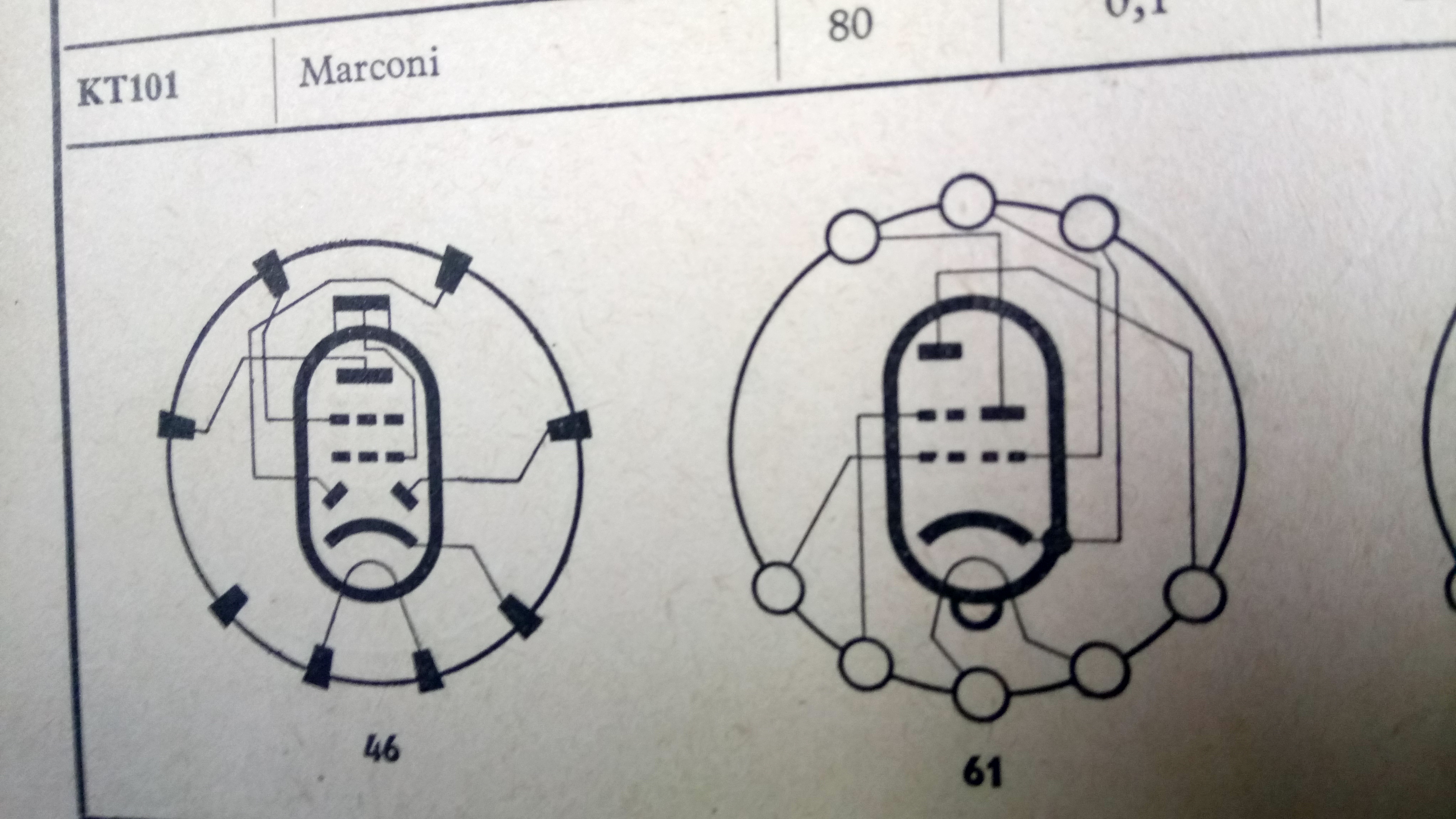
And regarding the reliability of German radio lamps of the "helmet" type, I can say that these are extremely reliable radio lamps, the most reliable of all European ones. Here are some more photos with a diagram of their internal structure.
Ретро радіо музей ТБ. Antique Radio MuseumTV
https://www.youtube.com/user/RadioSvit
Sincerely Peter
З повагою Петро
Posts: 16,582
Threads: 574
Joined: Oct 2011
City: Jackson
State, Province, Country: NJ
The 120VAC mod schematic. The PDF is a nicer one, but for a quick look I captured my CAD's screen.
I also added 500K resistor across that 3.3uF cap. It could be added across the input voltage also. Whichever is more convenient.
Note to folks who sub the ballasts with caps: same as across X-cap, a bleeder resistor is always needed. A 3.3uF cap is a large cap, and will store a lot of charge at potentially full input voltage peak.
500K will make for roughly 1.6 seconds discharge time and negligible electric effect while working, and negligfible power dissipation, hence the value.
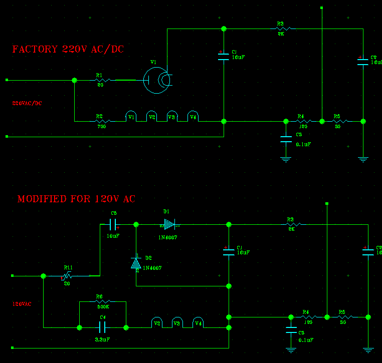
A convenient place for me to put it is right across that cap.
PS. I also tried introducing X-Cap (0.47uF) across the AC lines, no effect. Y-cap already is there, 0.1uF between the Negative (lower AC line) and the GND, so no sense adding anything.
People who do not drink, do not smoke, do not eat red meat will one day feel really stupid lying there and dying from nothing.
Posts: 1,942
Threads: 129
Joined: May 2008
City: Omak
State, Province, Country: WA
Hello mike,
Very nice !
Sincerely Richard
Posts: 4,950
Threads: 54
Joined: Sep 2008
City: Sandwick, BC, CA
Interesting, not what I expected, on an octal tube the heater pins are usually on pins 7 and 8, shield is pin 1, and cathode is usually pin 8, but on those stahl tubes they put the cathode and heater pins on opposite sides of the socket. Does that glass tube with the same base use the same horizontal structure or is it more conventional?
Regards
Arran
Posts: 664
Threads: 23
Joined: Nov 2014
City: Svalyava. Transkarpatia
State, Province, Country: Ukraine
Quote:Does that glass tube with the same base use the same horizontal structure or is it more conventional?
Arran. High-power glass tubes (output pentodes, output tetrodes and rectifiers) have a traditional design with a vertical armature.
Ретро радіо музей ТБ. Antique Radio MuseumTV
https://www.youtube.com/user/RadioSvit
Sincerely Peter
З повагою Петро
Posts: 16,582
Threads: 574
Joined: Oct 2011
City: Jackson
State, Province, Country: NJ
Yes the glass tubes seem to be traditional/vertical.
UCL11, 1st and output audio tube.
https://www.radiomuseum.org/tubes/tube_ucl11.html
UY11, half-wave rectifier.
https://www.radiomuseum.org/tubes/tube_uy11.html
People who do not drink, do not smoke, do not eat red meat will one day feel really stupid lying there and dying from nothing.
Posts: 16,582
Threads: 574
Joined: Oct 2011
City: Jackson
State, Province, Country: NJ
I am trying to align the radio without the instructions.
Which is OK. I'd still like to have the alignment instruction, considering the bands and the oscillator have both trimmer caps and trimmer coils.
But I have started with IF, which is 473kHz, and while I successfully passed it via antenna input (this one has no grid caps to disconnect), the trimming is a whole different matter.
The IF is adjusted by the screw core, and while the ones at the bottom of the IF transformer are easily accessible, and I was able to mold a tip holder of a ball pen to be my socket driver, the ones accessible from the top are about 1/2" inside the bobbin, and the diameter of the inside of the bobbin is about 1mm wider than the core's hex width (4mm side-to-side, 4.2mm corner-to-corner).
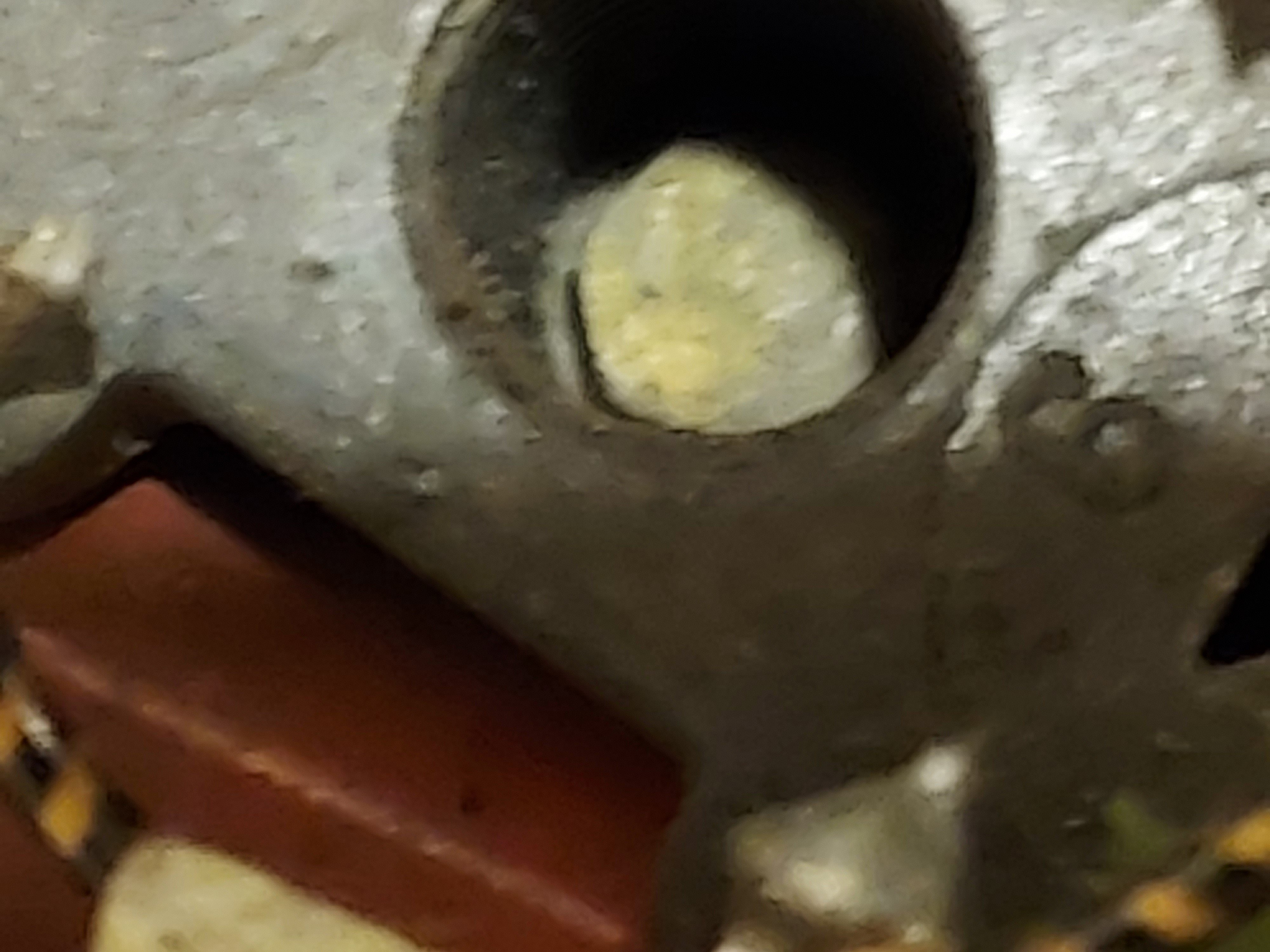
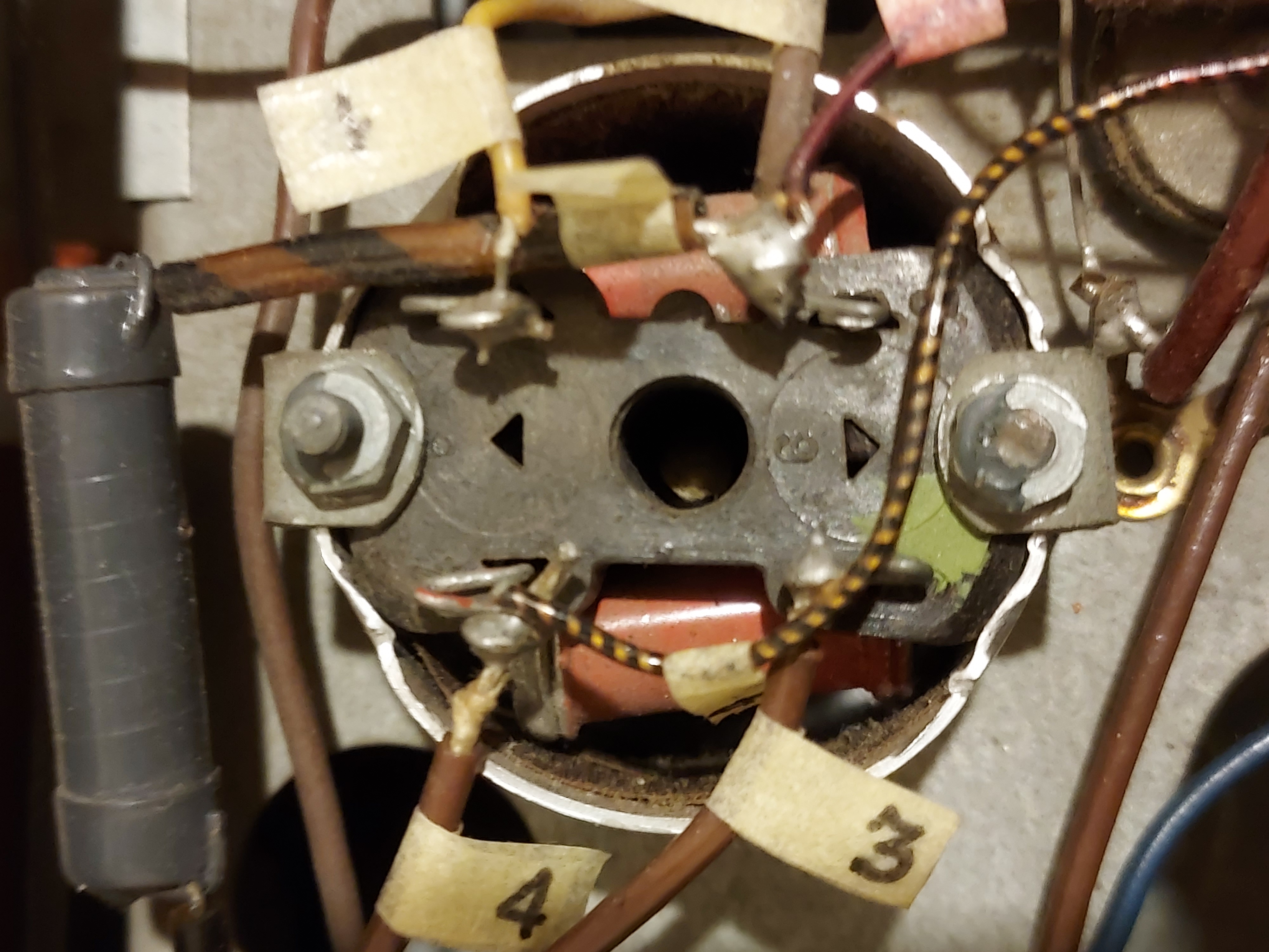
I am trying to figure how to access it. It needs to be hard plastic nut driver with very thin walls. I am sure there was such a tool available to Telefunken techs, but, well, those wonderful days are long gone.
Time to join Radiomuseum. I am sure there are folks there with this specific experience.
People who do not drink, do not smoke, do not eat red meat will one day feel really stupid lying there and dying from nothing.
Posts: 664
Threads: 23
Joined: Nov 2014
City: Svalyava. Transkarpatia
State, Province, Country: Ukraine
Michael, all pre-war intermediate frequency transformers Telefunken used ferrite cores with a very interesting feature - they can be adjusted both from the bottom of the chassis and from above. And on one side of such a core was 6-sided, and on the other - for a flat screwdriver. Look at the IF transformer from above, there may be direct access to the ferrite core from above. It may be necessary to remove the screen from the IF transformer.
Ретро радіо музей ТБ. Antique Radio MuseumTV
https://www.youtube.com/user/RadioSvit
Sincerely Peter
З повагою Петро
(This post was last modified: 06-18-2023, 05:52 AM by RadioSvit.)
Posts: 16,582
Threads: 574
Joined: Oct 2011
City: Jackson
State, Province, Country: NJ
Peter
Don't you think I've looked? 
Yes I have.
No, no through holes to access the second core. And both ends are for hex nut driver (hex socket).
This is not the 1st time I see that: I forgot, but methinks, in the portable Stromberg Carlson. The access from the top, you have to move the hex tool further to adjust the second core.
As you could see from the photo, no hole in the core. Same from the other side.
But what says "Lasciate ogne speranza, voi ch'entrate" better than anything, (abandon hope all ye who enter here) is the German phrase "The other core is accessed from the top" right at the diagram.
I hate cores.   I like trimmer caps.  
People who do not drink, do not smoke, do not eat red meat will one day feel really stupid lying there and dying from nothing.
Posts: 16,582
Threads: 574
Joined: Oct 2011
City: Jackson
State, Province, Country: NJ
Well, I have aligned IF.
I made a tool. One more BiC ball pen lost its life, but it was not for naught!
First of, it is a well-known way of making makeshift nut drivers, molding heated plastic tube (semi-translucent ballpens are ideal, exactly the plastic that is hard enough, easily molded but does not crack) around the hex shape to be driven.
This time it was not the pen main trunk but the small cone that holds the cartridge tip itself.
I drilled a suitable hole in a piece of wood, to serve as a stable holder, and shaved the cone-shaped tip-holder to be a cylinder of about 5mm or so in diameter, to fit inside the well to reach the ferrite slug.
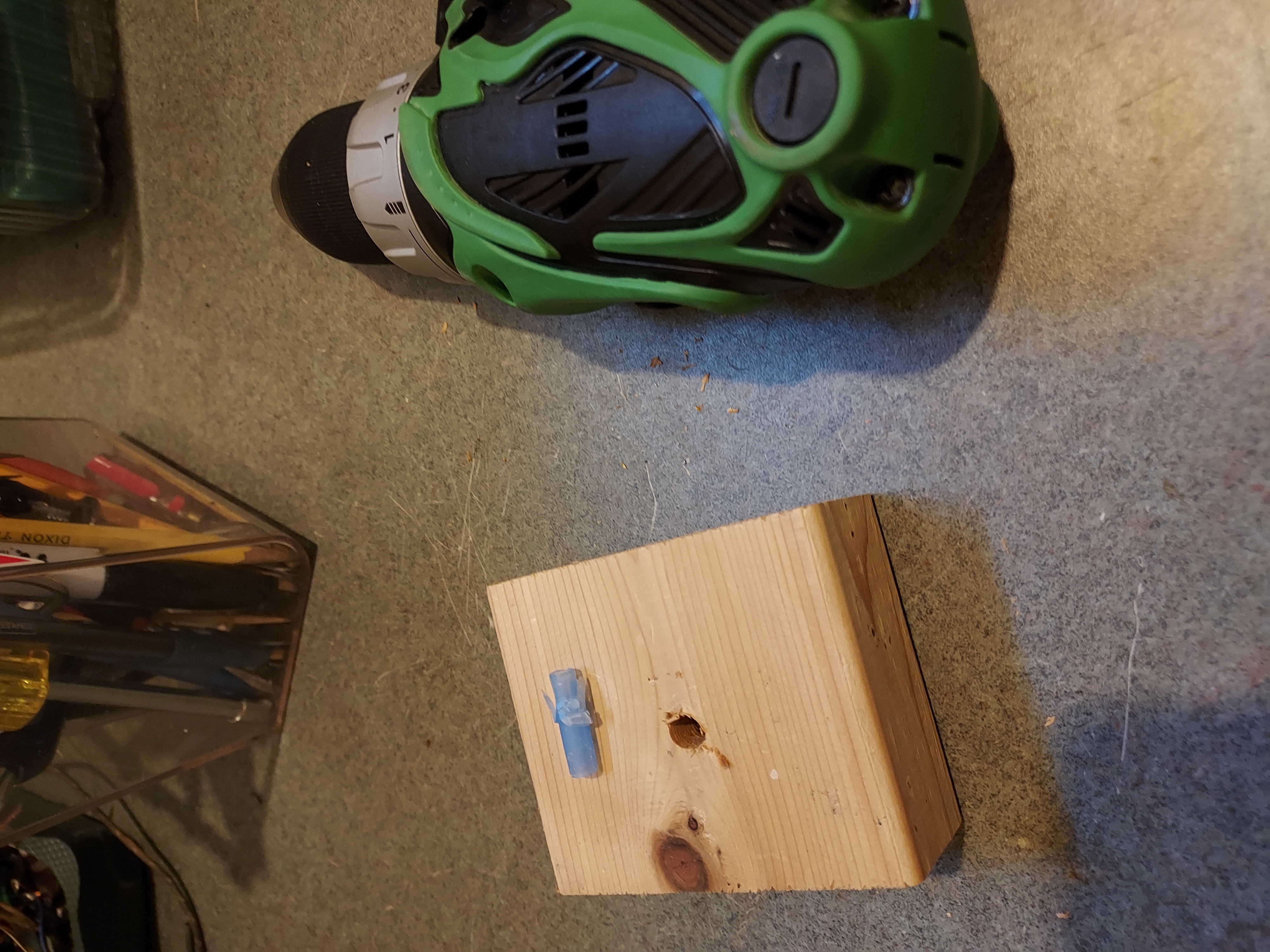
In went the cone, and I shaved it with my Exactlo knife into a cylinder.
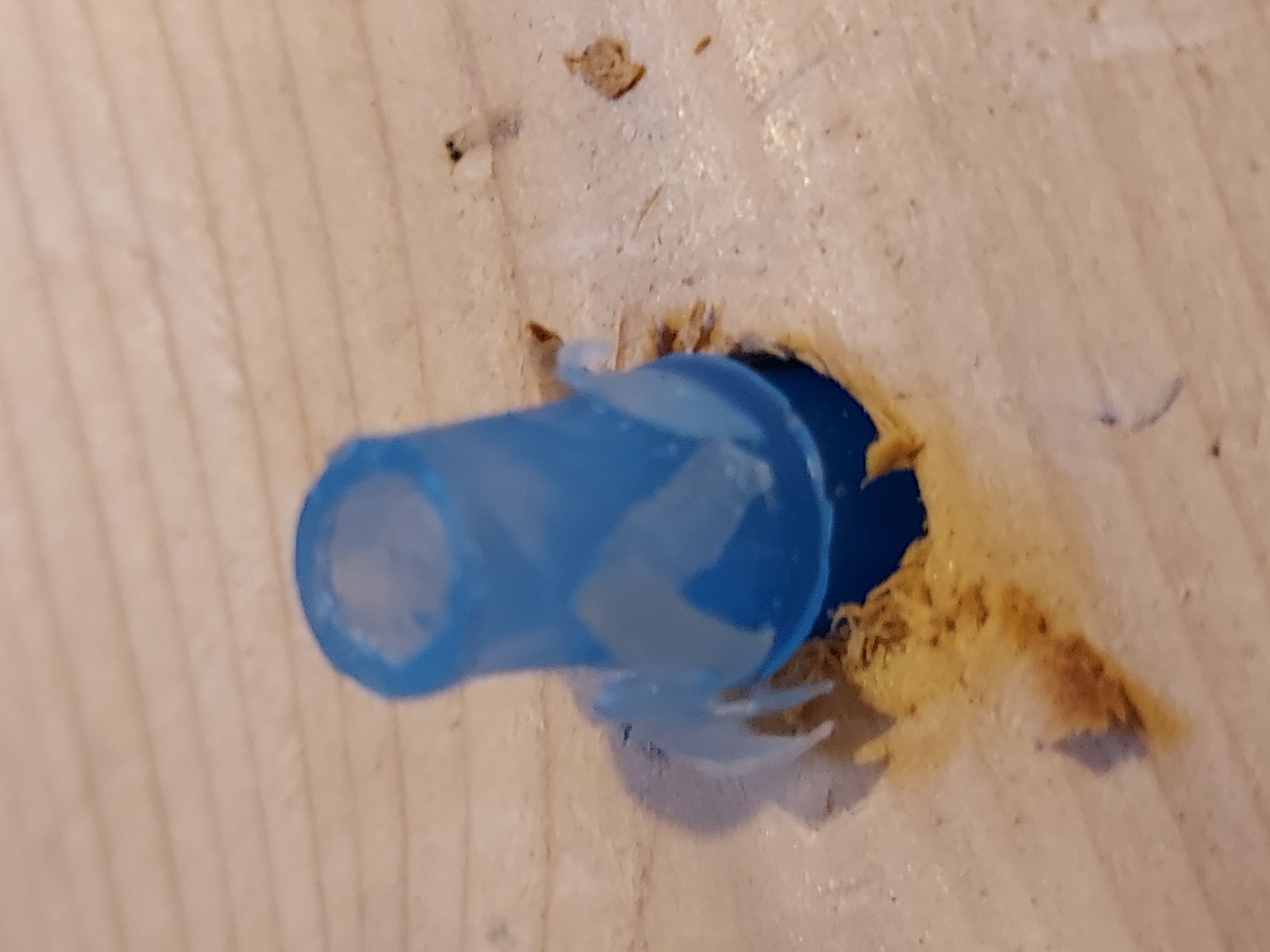
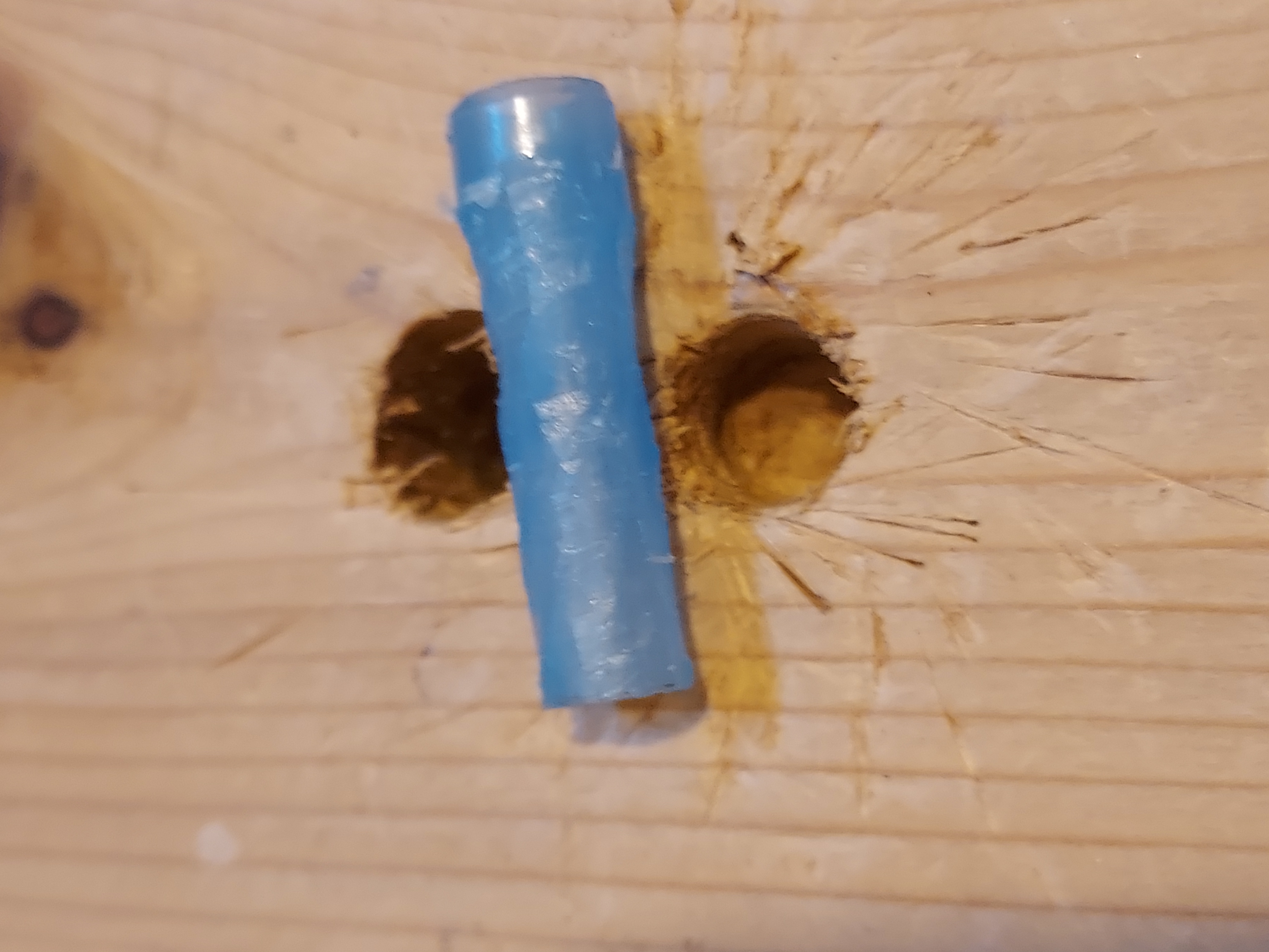
Then I used the bottom slug to morf the heated cylinder into the nut-driver shape. The slug sticks out so it is ideal to form the hex shape. Earlier I formed another cone to serve as a driver for these, but it only is usable for these bottom cones, as they are readily accessible.
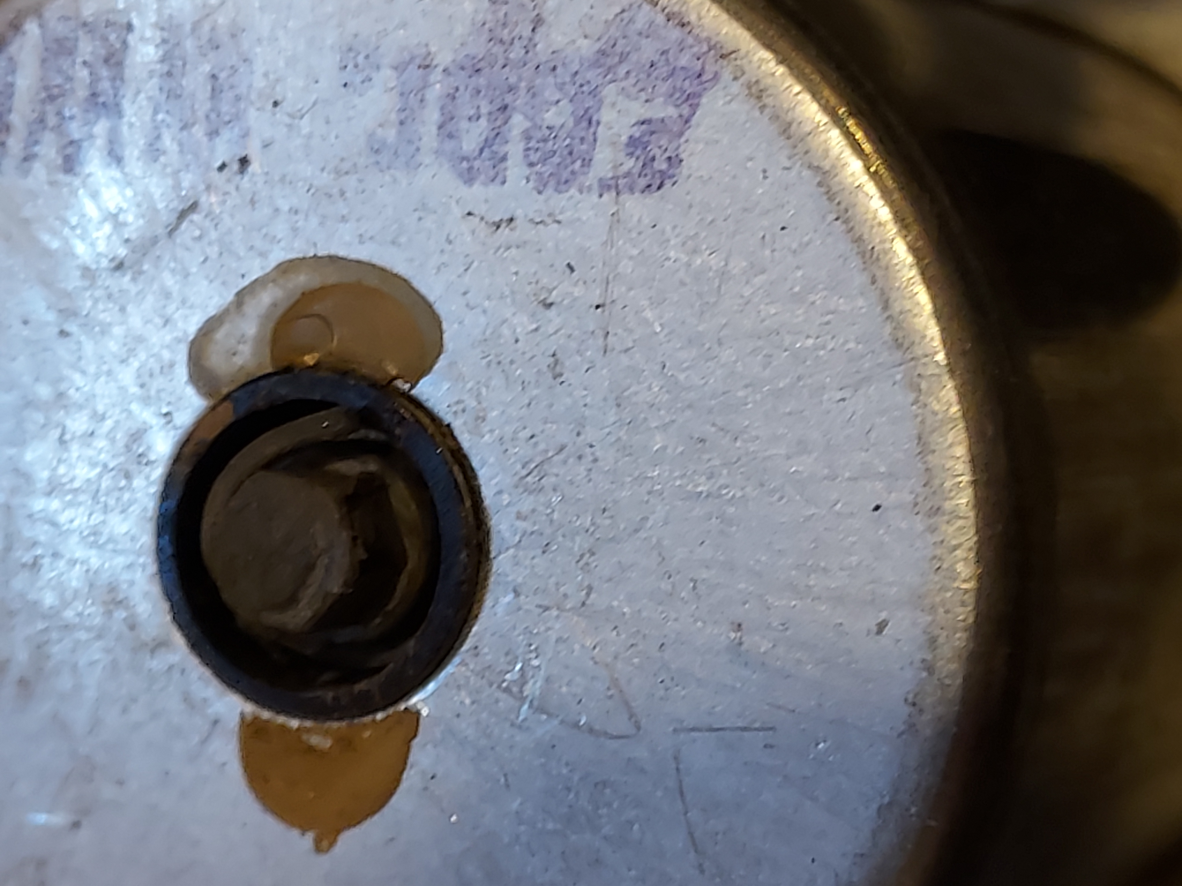
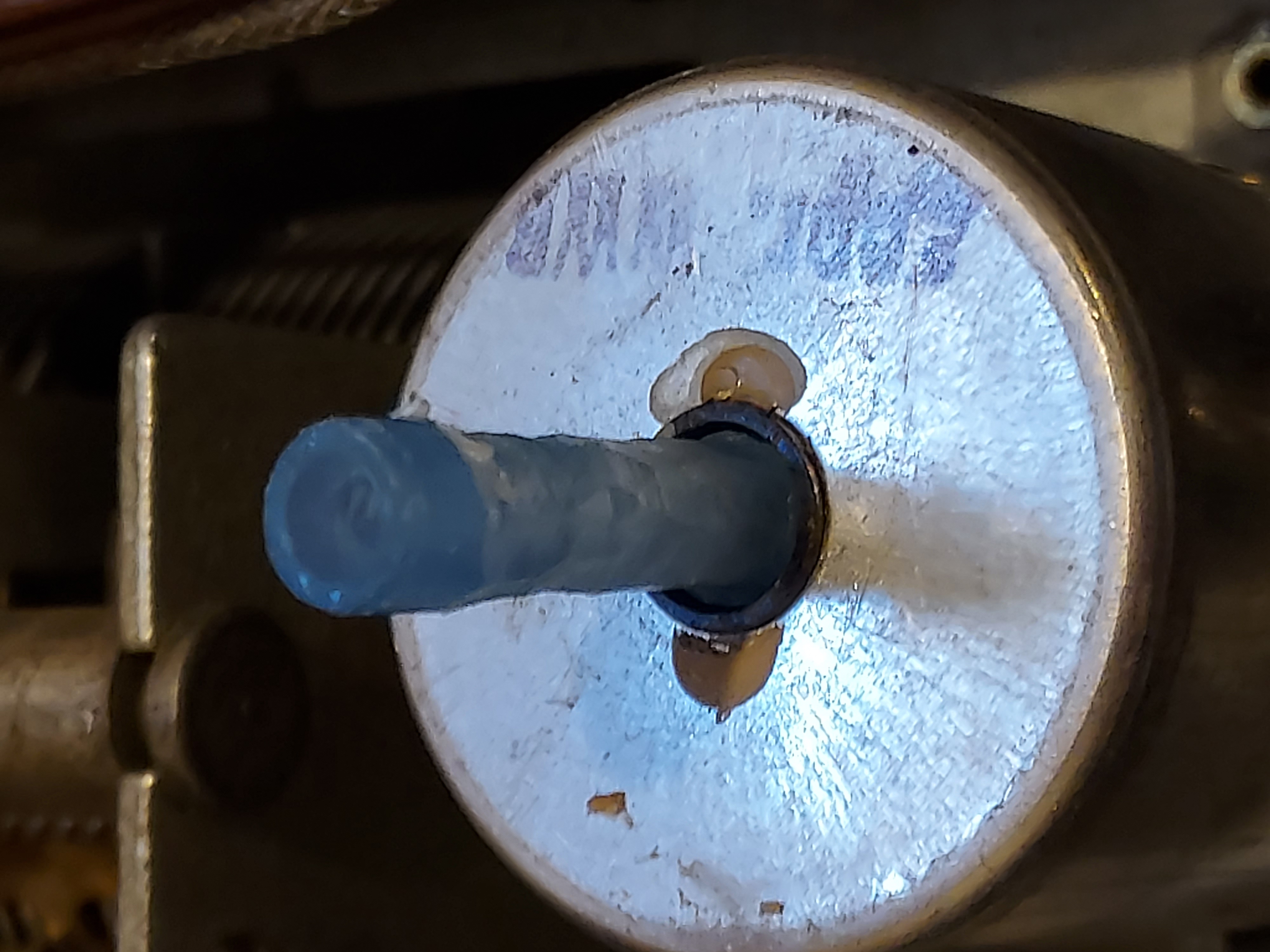
After the cylinder cooled off, and became solid, I took it off the slug
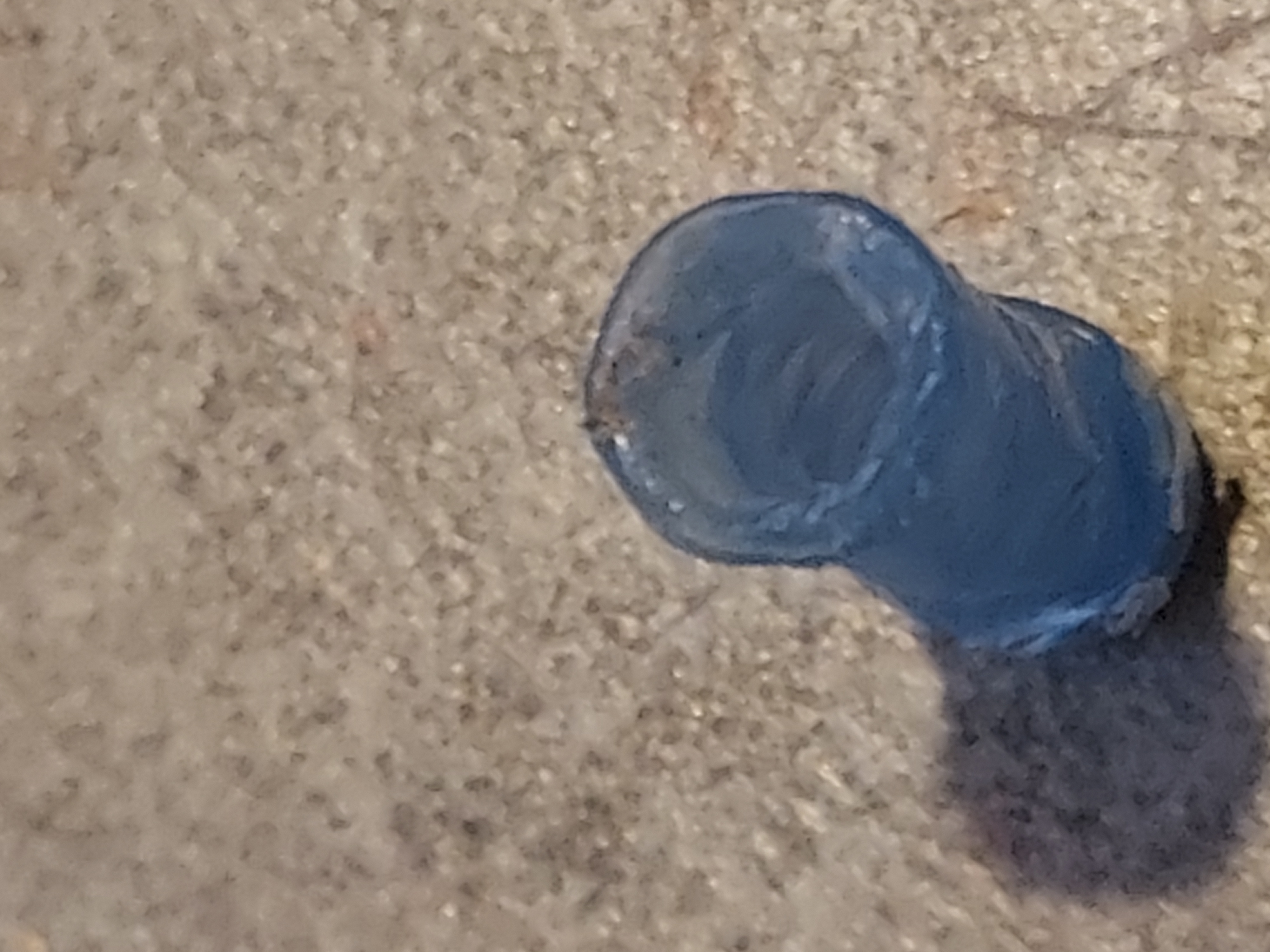
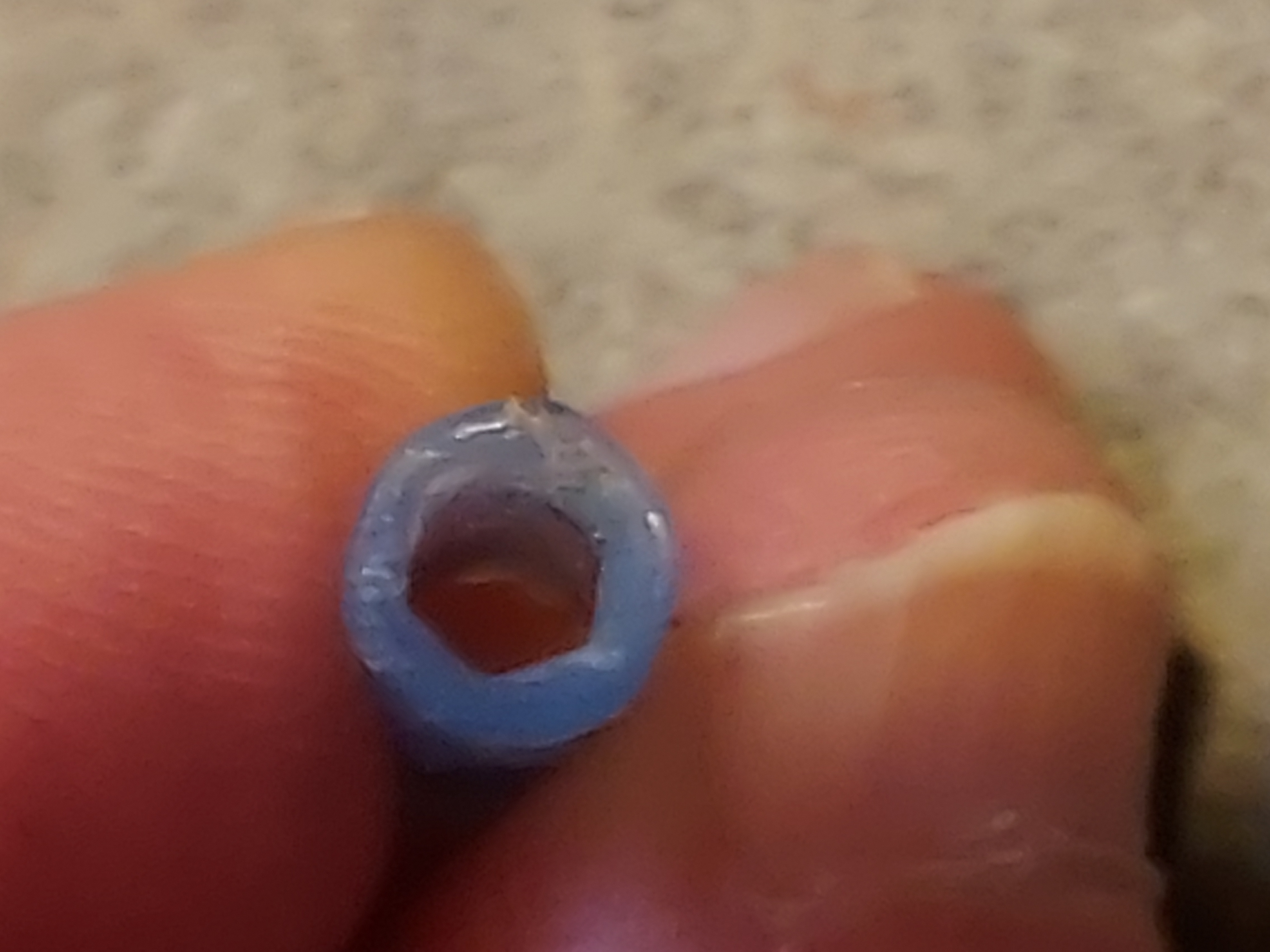
Then with my Exactto trimmed the edges that bulged up a bit, which would preclude the cylinder from going inside the well, and glued it into the ball pen.
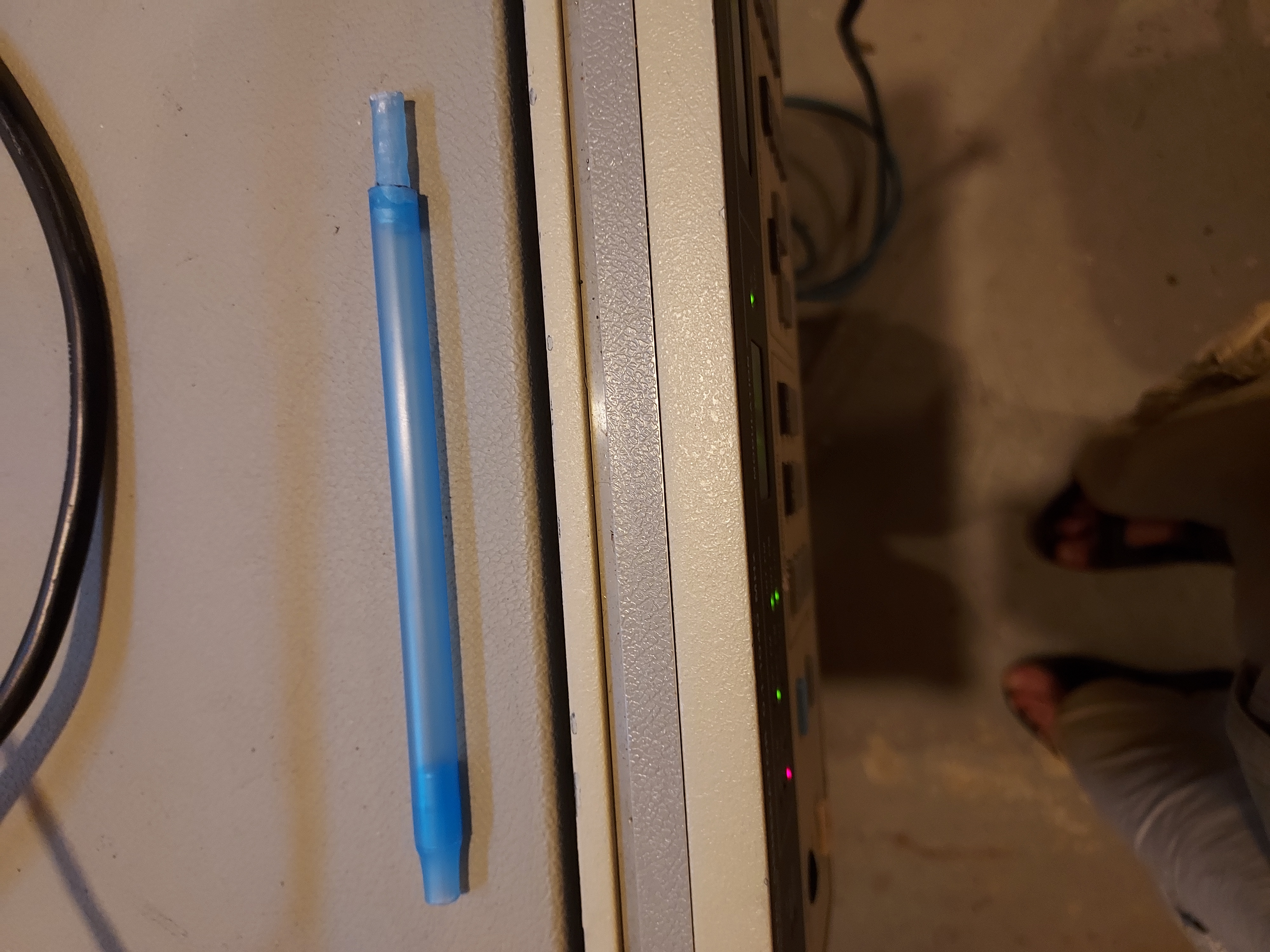
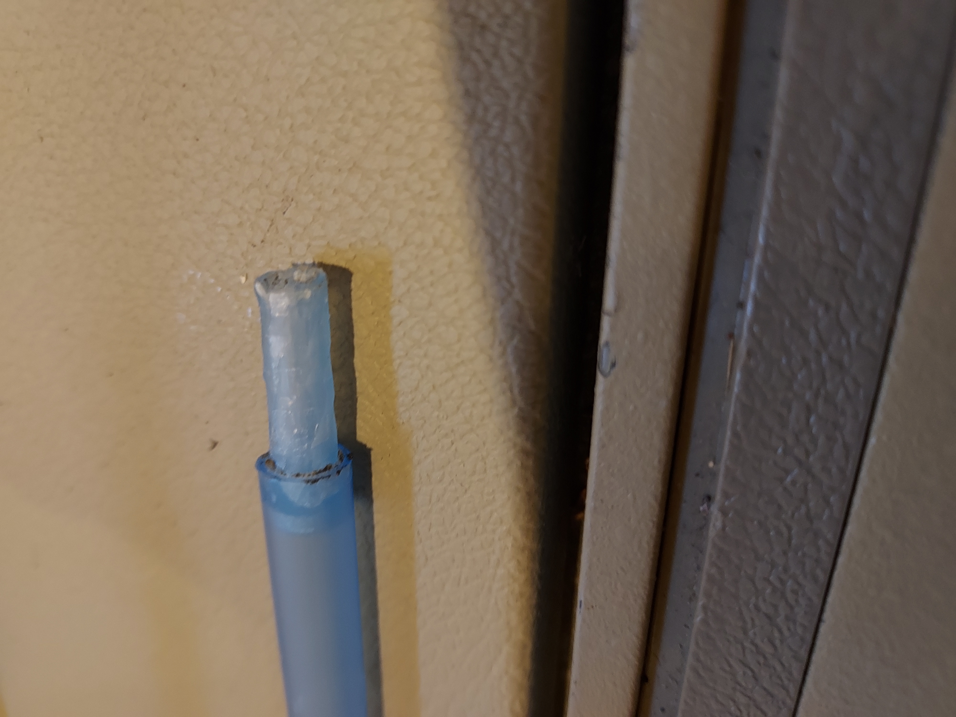
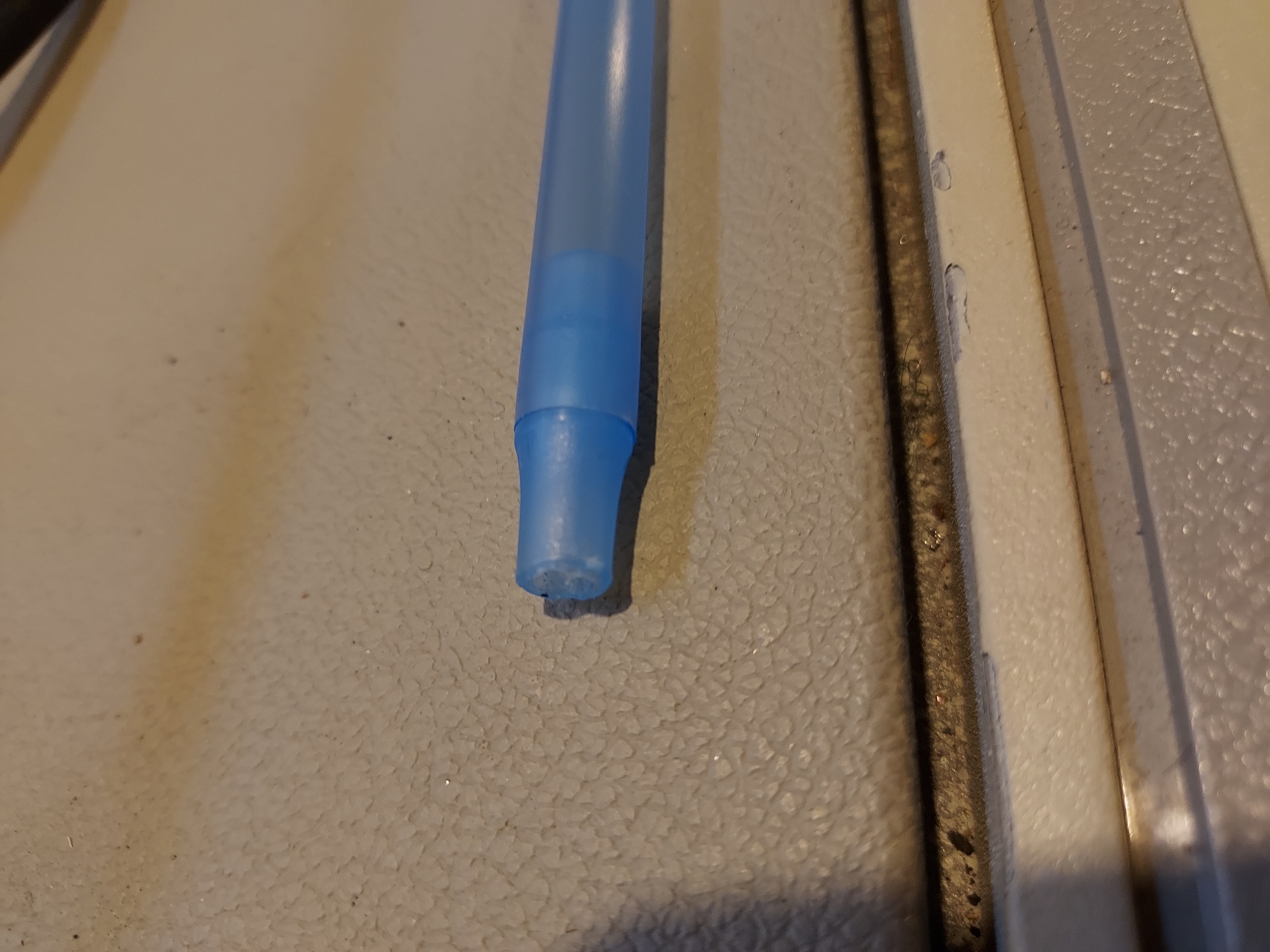
Now I have a universal tool to drive the slugs that stick out or hide inside.
I checked the alignment of the BC: since the clear marks for the needle positions are not there, I was satisfy to see that about between the middle to the left end of a number the SG would make the radio beep.
The local station now is extremely loud, even at low volume, and there are many stations pulled by using that 4" (about 10cm or so) piece of wire
as an antenna.
There is mostly noise on LW and SW (I will have to see SW during the dark part of the day with some better antenna, outside the basement).
I hope today I will put the radio together to bring it with me to FL, to show to mom.
People who do not drink, do not smoke, do not eat red meat will one day feel really stupid lying there and dying from nothing.
Posts: 16,582
Threads: 574
Joined: Oct 2011
City: Jackson
State, Province, Country: NJ
BTW, this is true hot chassis radio: the chassis is connected to an AC IN pin through overall 150 Ohms of resistance. And, notice, in Europe the plugs were not polarized (well, so were they not in the old US), but in addition it is 220V.
So everything is insulated. But. The metal speaker cover/shield is connected to the chassis via 5,000 pF cap.
While that will not give you any serious jolt, one will feel it if touching it while standing barefoot imn a wet basement or ground. 
People who do not drink, do not smoke, do not eat red meat will one day feel really stupid lying there and dying from nothing.
Posts: 4,950
Threads: 54
Joined: Sep 2008
City: Sandwick, BC, CA
Mike;
A weird thing is that some older outlets were polarized, but I never saw a polarized plug on any device until the 1980s, and that included extension cords. The strange part is that I often see them on devices where a polarized plug would make no difference, like in double insulated things like hair dryers. I think that the theory may have been that if something needed to be polarized then they would put a ground on it as well.
Regards
Arran
Posts: 16,582
Threads: 574
Joined: Oct 2011
City: Jackson
State, Province, Country: NJ
Arran
Yeah, we rented our apartment in Brooklyn NY in 1989, and none of the outlets were polarized.
Then my parents bought their co-op in 1995, and the same thing was there, all outlets were very old and non-polarized.
Of course, a highrise building, carpet/wood floors, no grounded structures nearby.
Kitchen is an entire different matter. I do not remember if there were outlets with a GND pin there, and how the fridge was plugged in.
I do remember that back on Russia, when our fridge was touched, one would feel a little "bite", as we called it. Not a real jolt, but unpleasant stinging sensation.
People who do not drink, do not smoke, do not eat red meat will one day feel really stupid lying there and dying from nothing.
Posts: 13,776
Threads: 580
Joined: Sep 2005
City: Ferdinand
State, Province, Country: Indiana
Interesting. I've replaced almost all of the original 1960 ungrounded outlets in this house, and they were all polarized although ungrounded.
--
Ron Ramirez
Ferdinand IN
Users browsing this thread: 1 Guest(s)
|
|
Recent Posts
|
|
Philco Model 38-7: what caps & resistors do fail typically?
|
| Since you stated earlier, you have a console 38-7XX. They also had a 38-7T (table), and 38-7CS (chairside). A very nic...GarySP — 01:18 PM |
|
Part numbers to model cross
|
| That I wouldn't know, but sometimes the radio document itself shows one, same as the capacitor cans' etc pinouts.morzh — 12:46 PM |
|
Part numbers to model cross
|
| Thank you morzh, that is exactly what I was looking for. Now , is there some where that shows pinouts for Philco power ...Jim Dutridge — 11:37 AM |
|
Restoration of the Canadian General Electric A-87
|
| Thanks for your help Michael. In fact, this video is only an intermediate result. Later I had to apply another tinting l...RadioSvit — 09:01 AM |
|
Restoration of the Canadian General Electric A-87
|
| Great job on the cabinet.
PS. In the US notation, "kenotron" refers to specific type of tubes; we call re...morzh — 08:24 AM |
|
Part numbers to model cross
|
|
This document has at least some tables of models and parts used.
Example: Choke 32-7572, used in 604 radio.
Search f...morzh — 08:19 AM |
|
Restoration of the Canadian General Electric A-87
|
| I also checked all the radio tubes on my Hickok 530 tube tester. The 5Z3 kenotron turned out to be faulty, all the other...RadioSvit — 08:02 AM |
|
Restoration of the Canadian General Electric A-87
|
|
Well... While the varnish is drying up, I started repairing the chassis...
Of course I started by replacing the pa...RadioSvit — 07:12 AM |
|
Philco Model 38-7: what caps & resistors do fail typically?
|
| Hello Martin,
Welcome aboard our little community what great Model 38-7
Sincerely Richardradiorich — 12:30 AM |
|
Philco Model 38-7: what caps & resistors do fail typically?
|
| Welcome to the Phorum Martin.
I count about 9 paper caps, the 3 electrolytic caps and 2-Y2 safety caps to replace th...RodB — 09:44 PM |
|
Who's Online
|
| There are currently no members online. |

|
 
|
That is, the filament, cathode, grid and anode are in a horizontal position, not in a vertical position! As it was in radio lamps at the beginning of the 20s


![[-] [-]](https://philcoradio.com/phorum/images/bootbb/collapse.png)


