1935 Philco 60B, Version 6, Run #11, Oscillator Cap
Posts: 42
Threads: 12
Joined: Mar 2023
City: Lancaster
State, Province, Country: PA
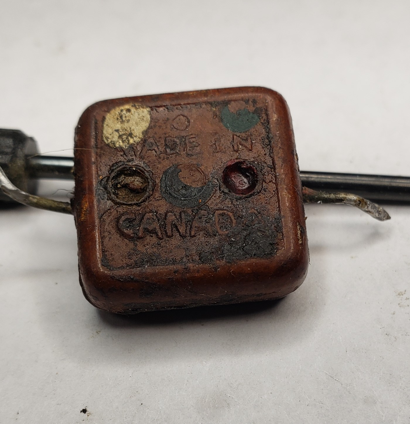
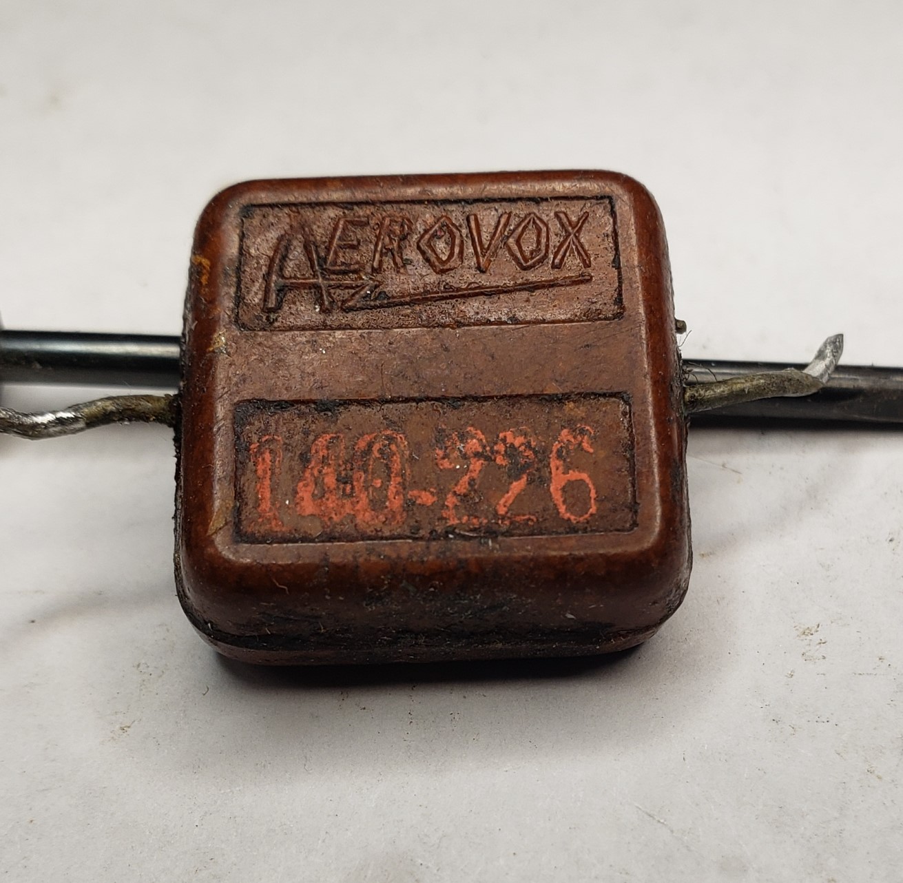
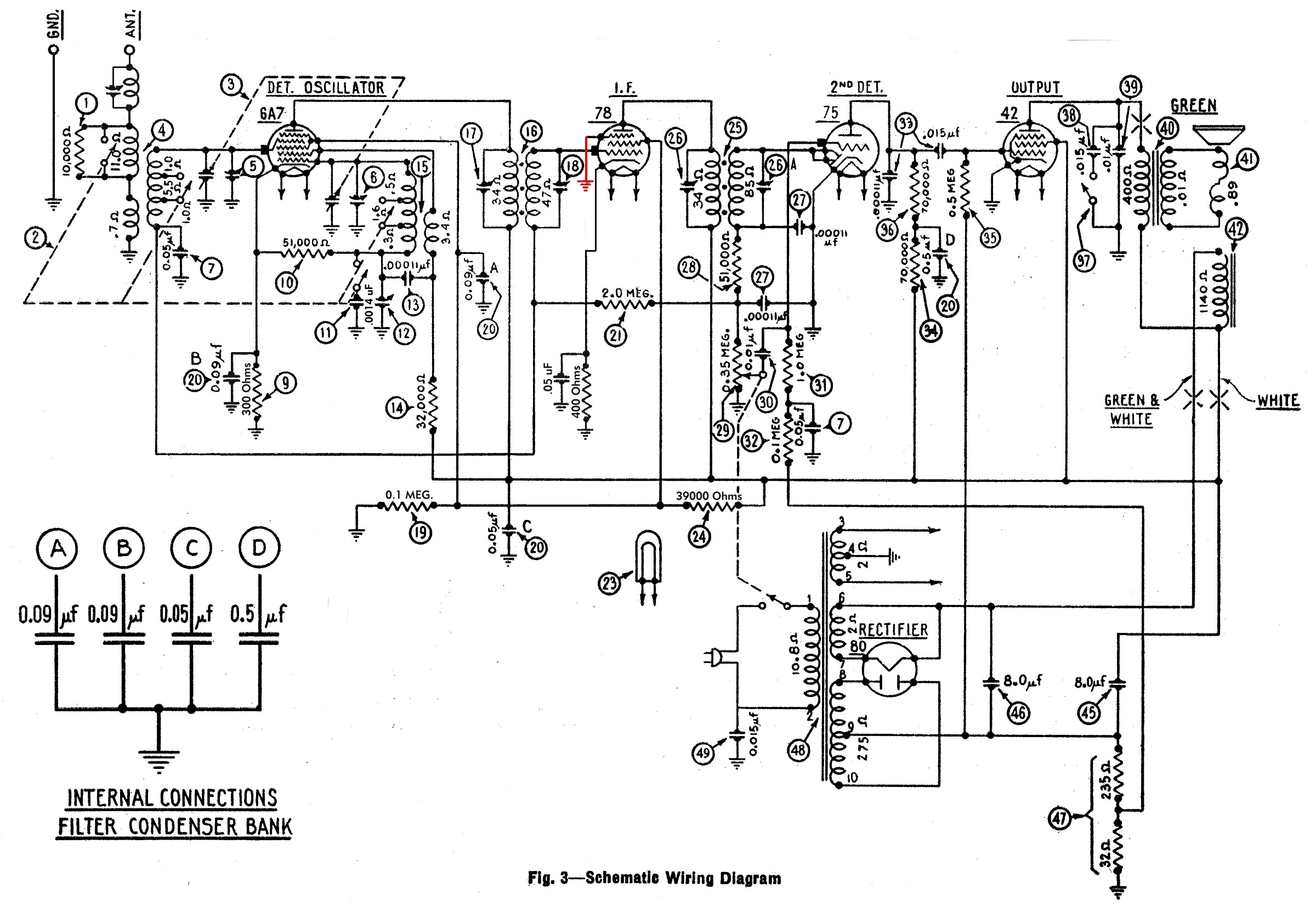
I'm puzzled over an Aerovox Mica Cap on this set and it's correct value. I attached pictures of the device and the schematic. It is Item #13 across the Oscillator Coil windings, shown on the schematic as a 110pf. The value has remained the same over the range of different Run's.
In the picture, the Part Number appears to be 140-226. Colors across the top, L-R are, White & Green. Colors across the middle, L-R are, Unknown, Black & Red.
On my DVM Capacitance it reads as a 0.00112mf, BUT I don't trust that on old leaky caps. My EICO 950 Capacitance Bridge reads approx. 0.0014mf. Both are reasonably close, however, the schematic states 110pf!! Off by a factor of 10.
So, I think I should keep the original one, since it appears to be OK, or replace it with a new 0.001mf. But 110pf seems to be questionable. The original does not appear to be leaky. And I am not proficient enough to decode the color for the stated capacitance. I couldn't find any references to the Aerovox Part number.
I'm not sure of it's technical purpose, and how critical the value is.
Thoughts on the correct replacement?
Thanks
John N3MUN
Posts: 16,533
Threads: 573
Joined: Oct 2011
City: Jackson
State, Province, Country: NJ
I doubt it is the original cap. I am not sure Philco would use Aerovox-marked caps.
I think the correct replacement is a 110pF mica cap.
People who do not drink, do not smoke, do not eat red meat will one day feel really stupid lying there and dying from nothing.
Posts: 42
Threads: 12
Joined: Mar 2023
City: Lancaster
State, Province, Country: PA
Thanks!
Thanks
John N3MUN
Posts: 714
Threads: 9
Joined: Apr 2018
City: S. Dartmouth
State, Province, Country: MA
Aerovox would often apply the EIA 6 dot code to 3-dot bodies 
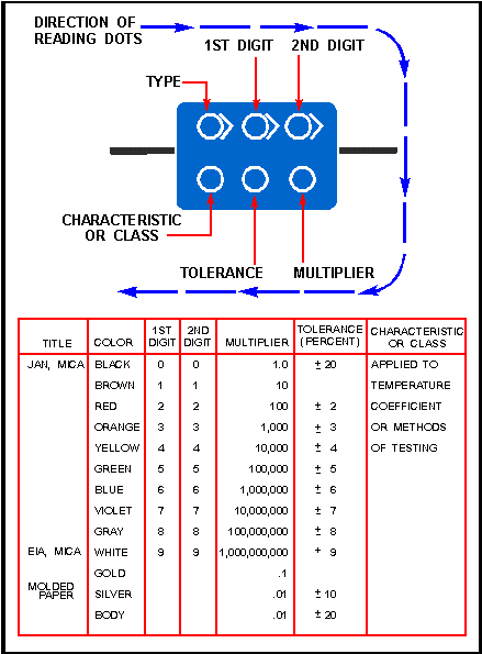
Thus the upper left is white for EIA, the 2nd dot has fallen away and should be brown, the third is as seen, green, the forth or multiplier is also brown but could be red, deteriorated, the fifth though important is if black 20%..
I have been reviewing a 25# box of new 30's era mica caps (yes, thousands of mica caps). Most are very accurate but some appear to be coded as if to fulfill a required quantity. None the less release agents if not removed from the body will cause the paint dots to fall away.
This cap will effect the calibration in the center of the band, so its value needs to be roughly 10% of stated, it should also have a negative co-efficient, generally N330.
FWIW take a look again at setup to read the value on your Eico bridge... The fact that the bridge gives a null, indicates the cap does not have excessive leakage. I have found that accumulated dirt stuck to the body of the molded mica cap contributes to leakage as read by some instruments... Sometimes the multiplication factor on the scale control knob becomes confusing, bad enough that the dots are too...
I keep a couple of known good marked caps that are in the center, more or less of each range, sanity check near my bridges...
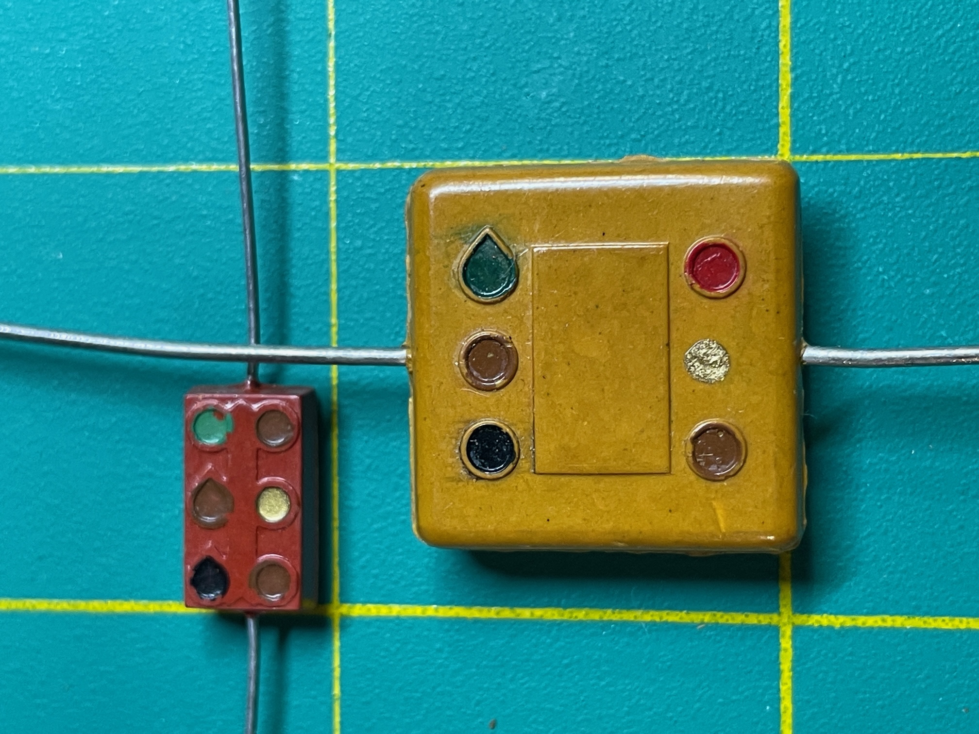
Note how much smaller the 150pf is over the 1500pf and the examples were for JAN production... Note too, the black first dot on JAN coding, more often than not, will be a cap that more likely has retained it value.
Do not substitute any other kind of cap in this location, though a tubular ceramic may work..
Chas
Pliny the younger
“nihil novum nihil varium nihil quod non semel spectasse sufficiat”
(This post was last modified: 10-05-2023, 11:17 AM by Chas.)
Posts: 106
Threads: 17
Joined: Mar 2018
City: angeles city,philippines
one fella on the ARF comm. radio section claims that filth on the outside of those things can alter the readings and show leakage if tested at near rated voltage. the shunt effect seems to make sense. contrary to popular belief they really can fail the most recent for me was a el menco mica across a bfo coil in a sx100. i'd be curious if you cleaned that up if it still tests the same out of idle curiosity
Posts: 1,151
Threads: 47
Joined: Feb 2015
City: Roseville, MN
I thought filth was an insulator. ;) Isn't that why all our radio chassis are covered with it?
Posts: 42
Threads: 12
Joined: Mar 2023
City: Lancaster
State, Province, Country: PA
Chas -
For some reason I did not receive notification there was a new response to this thread!
As always you provide a wealth of good information. Thanks!
I do occasionally check the accuracy of the Eico. It's pretty good. I also check on the different ranges, when the value is near either end of the range. I then check the leakage with the Mica Test and applying the internal voltage. In this case it also checked very good.
I liked the comparison in size that you made. So with this and all the other information, I don't think 110pf should be used, but rather 0.0011mf (Sorry, I'm still not into the nf values!)
I know that the schematics do have errors in them, and I guess we don't know for sure, unless we would have information from other sets of this Model to see what values were used in them.
I won't be able to confirm operation yet, as I'm trying to find a replacement 2nd IF transformer.
Good Luck on checking the thousand's of caps you have!
Thanks
John N3MUN
Posts: 1,885
Threads: 120
Joined: May 2008
City: Omak
State, Province, Country: WA
Hello John,
Yes I have had the same thing happen to me that why I check this site every day and yes Chas really is one smart cookie .
Some of those Capacitors can be confusing .
Sincerely Richard
P.S. Rob yes I restored a General electric clock radio a while back it even had saw dust like it was in someones workshop for years !
Posts: 714
Threads: 9
Joined: Apr 2018
City: S. Dartmouth
State, Province, Country: MA
Quote:Good Luck on checking the thousand's of caps you have!
Thanks!
I'm about 1/2 way through the mica cap project. It has occurred to me since what I have seems to be general sampling of manufacturers, yet, I did not do a count of each, I can, this early, come to a conclusion that Micamold mica caps have, even new, a higher failure rate, generally, high leakage or shorted. All others are somewhat equally distributed for failures..
I "had" faith in Micamold mica, but I am feeling that there must have been some "contamination" in their process that not only caused "early" failure of Micamold Bakelite cased paper caps but also their mica line. I will recklessly guess it was, possibly, that, high volume wartime work that set longevity aside 
How the other manufacturers rate is yet unknown until I get everything tested.
jjfritz5528
Have you created a post about this defective IF transformer? I would like to see the other shield for identification and the internal bobbin and what you have done so far...
If the OEM defective winding is totally intact, it is possible to rewind under certain mechanical conditions. Of which, could the bobbin be placed into a Morris winder to generate a new universal wind, or is it a solenoid wind with one winding on top of the other?
Point me to that topic if it exists...
Thanks!
Chas
Pliny the younger
“nihil novum nihil varium nihil quod non semel spectasse sufficiat”
Posts: 13,776
Threads: 580
Joined: Sep 2005
City: Ferdinand
State, Province, Country: Indiana
The schematic calls for part (13) to be .00011 uF, part 4519.
The 1936 Philco parts catalog confirms part 4519 is .00011 uF. (Or, if you prefer, 0.11 nF.)
.00011 uF is equal to 110 pF.
The part should be replaced with a 110 pF capacitor, not an 1100 pF (.0011 uF or 1.1 nF) capacitor.
--
Ron Ramirez
Ferdinand IN
Users browsing this thread: 1 Guest(s)
|
|
Recent Posts
|
|
Philco newbie with P-1891-WA console questions
|
| Hello Jeff ,
Far as the Electrolytic capacitors go here is a list of parts.
that will work . I like using Nichicon and...radiorich — 09:50 PM |
|
Philco newbie with P-1891-WA console questions
|
| Well, I've been stumped at trying to get the first of 11 electrolytic capacitors. I got a schematic and have a list of t...Jeffcon — 07:54 PM |
|
Model 80 Antenna Issue?
|
| Thanks Gary and Rod.
I also found an article in the Philco Repair Bench under Service Hints and Tips, about installi...Hamilton — 12:32 PM |
|
Model 80 Antenna Issue?
|
| Hello Hamilton, here is a little information found in our Philco Radio Library at the bottom of the Home page. Hope it ...GarySP — 11:28 AM |
|
Model 80 Antenna Issue?
|
| I did as you suggested and touching the middle of the volume control did nothing so the coil has to be rewound. Any idea...Hamilton — 10:19 AM |
|
1949 Motorola 5A9M
|
| This would be the second portable in the "other radios" forum where I have a similar one in my collection. I h...Arran — 12:41 AM |
|
Looking for any info: 1977 Ford-Philco Console Hi-Fi Turntable and Radio
|
| Hi PittsburgTost.
The record changer looks like a Garrard or BSR (Likely Garrard). The spindles just pull out and pu...MrFixr55 — 11:57 PM |
|
Looking for any info: 1977 Ford-Philco Console Hi-Fi Turntable and Radio
|
| Hello PittsburghToast ,
Welcome aboard and it looks like gary may have something for you !
now if I dig through my se...radiorich — 11:35 PM |
|
Model 80 Antenna Issue?
|
| You are kind of on the right path. You can touch the grid cap of the Detector/Oscillator 36 tube. I'm expecting a respon...RodB — 08:48 PM |
|
Looking for any info: 1977 Ford-Philco Console Hi-Fi Turntable and Radio
|
| Welcome to the Phorum, PittsburghToast! I found an old thread that my interest you regarding the quality and worth of P...GarySP — 08:48 PM |
|
Who's Online
|
There are currently 348 online users. [Complete List]
» 3 Member(s) | 345 Guest(s)
|
|
|

|
 
|


![[-] [-]](https://philcoradio.com/phorum/images/bootbb/collapse.png)


