Philco 89B code 123 newbie
Posts: 11
Threads: 2
Joined: Aug 2024
City: Orange
State, Province, Country: CA
Getting started on my first Philco here, done some research and hopefully I now know enough to be dangerous. 
Overall it's in pretty good shape but it's missing a few things, most notably a speaker and output transformer. If anyone has a speaker and OT that will work (I understand it's the same speaker in a 19, 43 and 71) please let me know!
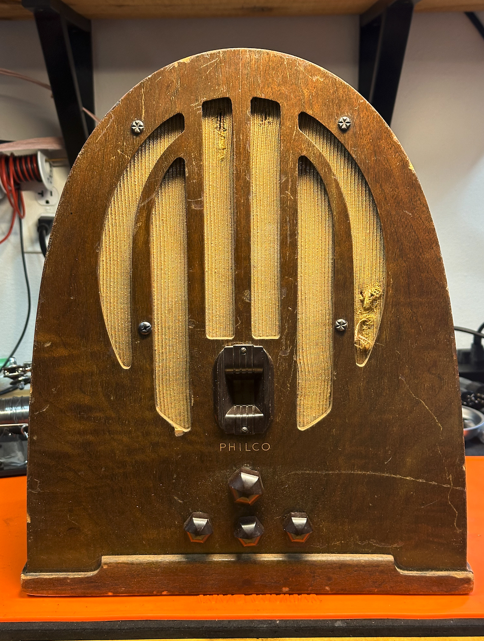
Not a lot of rust, either...
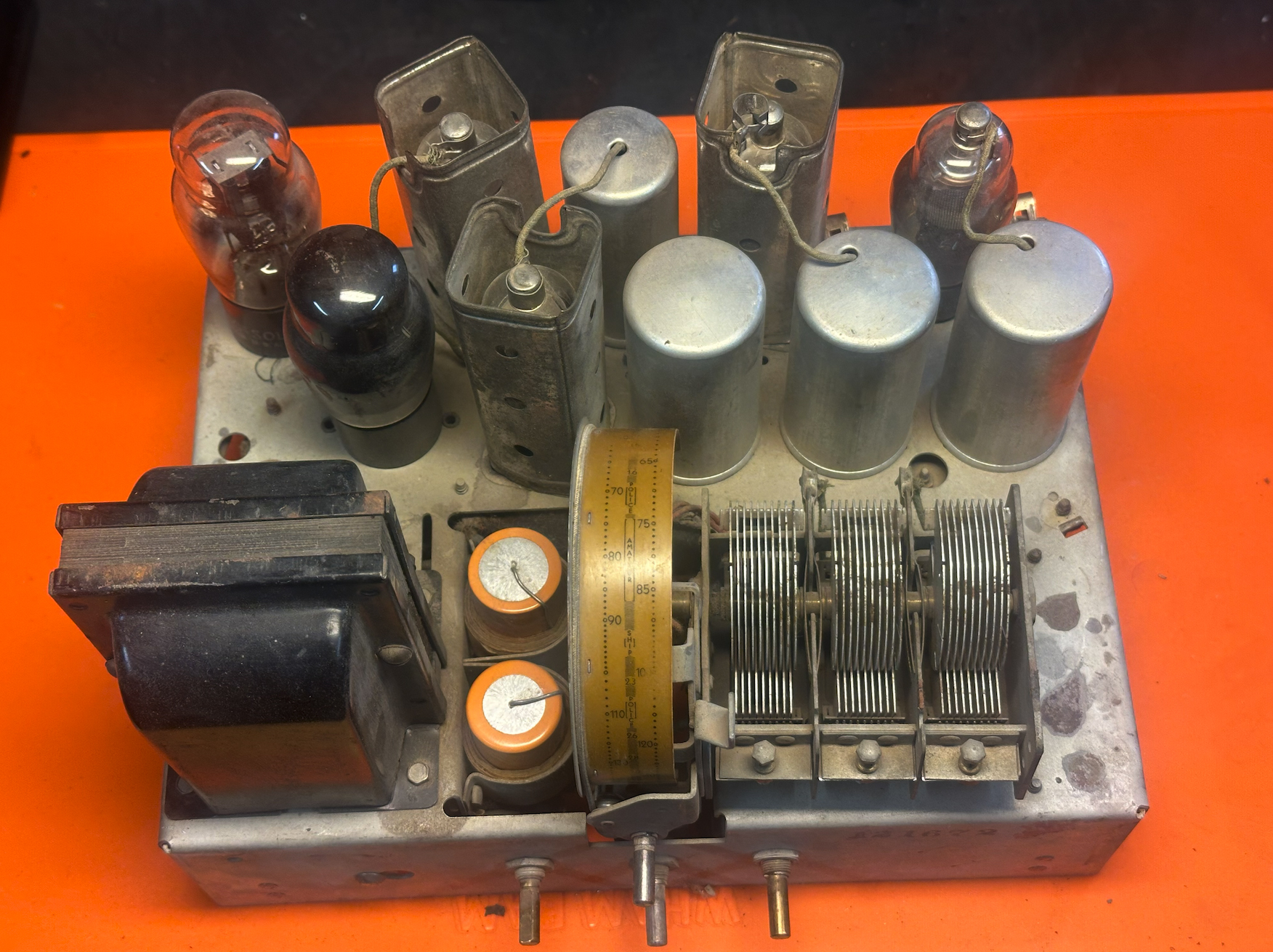
Not too much has changed but there are a couple of whacky things in here...
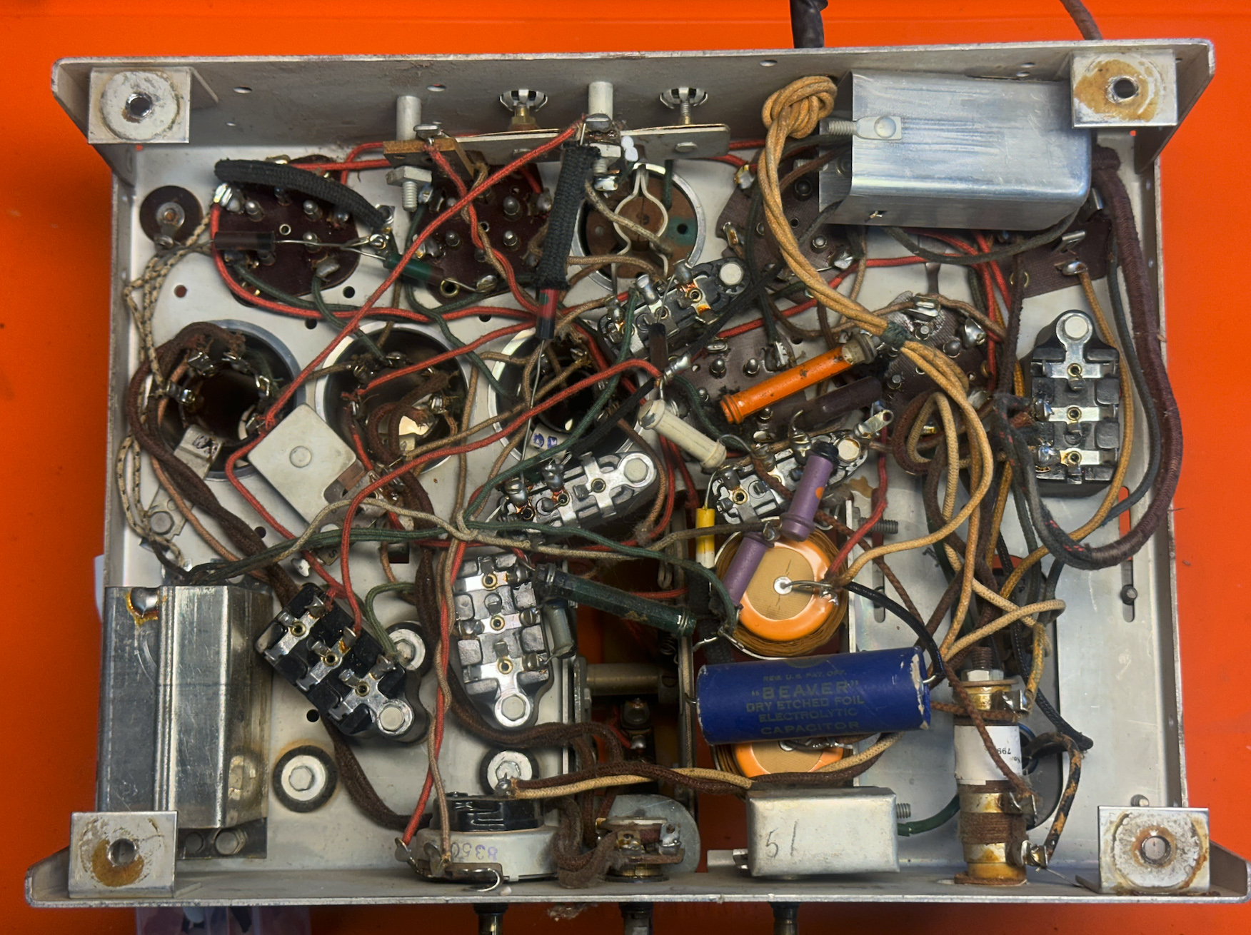
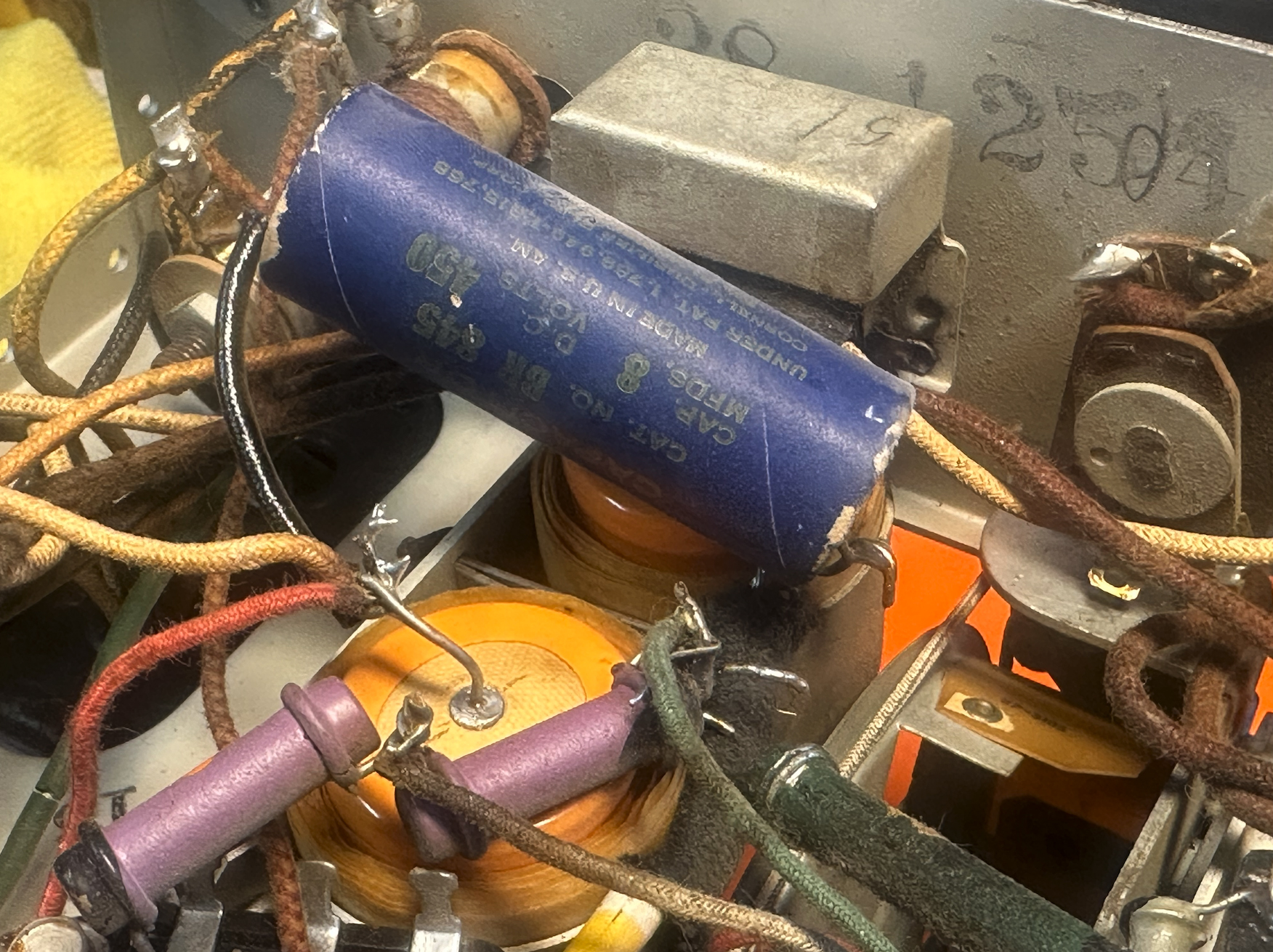
Looks like this cap was just tacked in, not sure if the old one is still in circuit but this is an easy fix...
I think this is supposed to be the 2nd IF transformer. Heh, looks like this was pulled from a 40s AA5, definitely doesn't match the other 89s layouts that I've seen online...
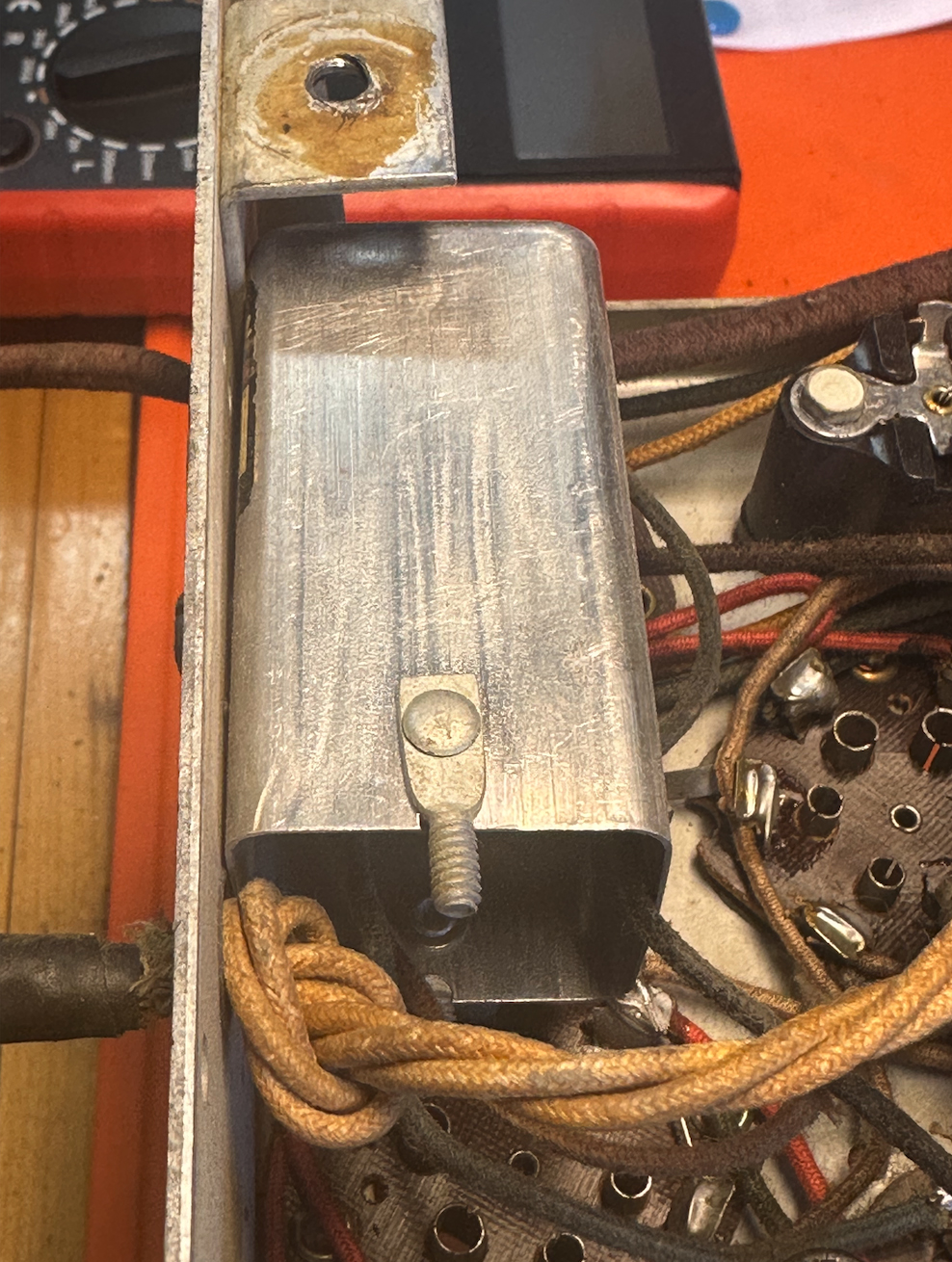
I followed the guide to removing the caps from the tar bakelite boxes and it was incredibly easy! I did 2 in around 20 minutes, way better than some of the horror shows I've seen on youtube. Sure they were the easiest two blocks to get to but I didn't have to unsolder any wires but it looks like these aren't going to be a hurdle after all. Replaced parts 36 and 17...
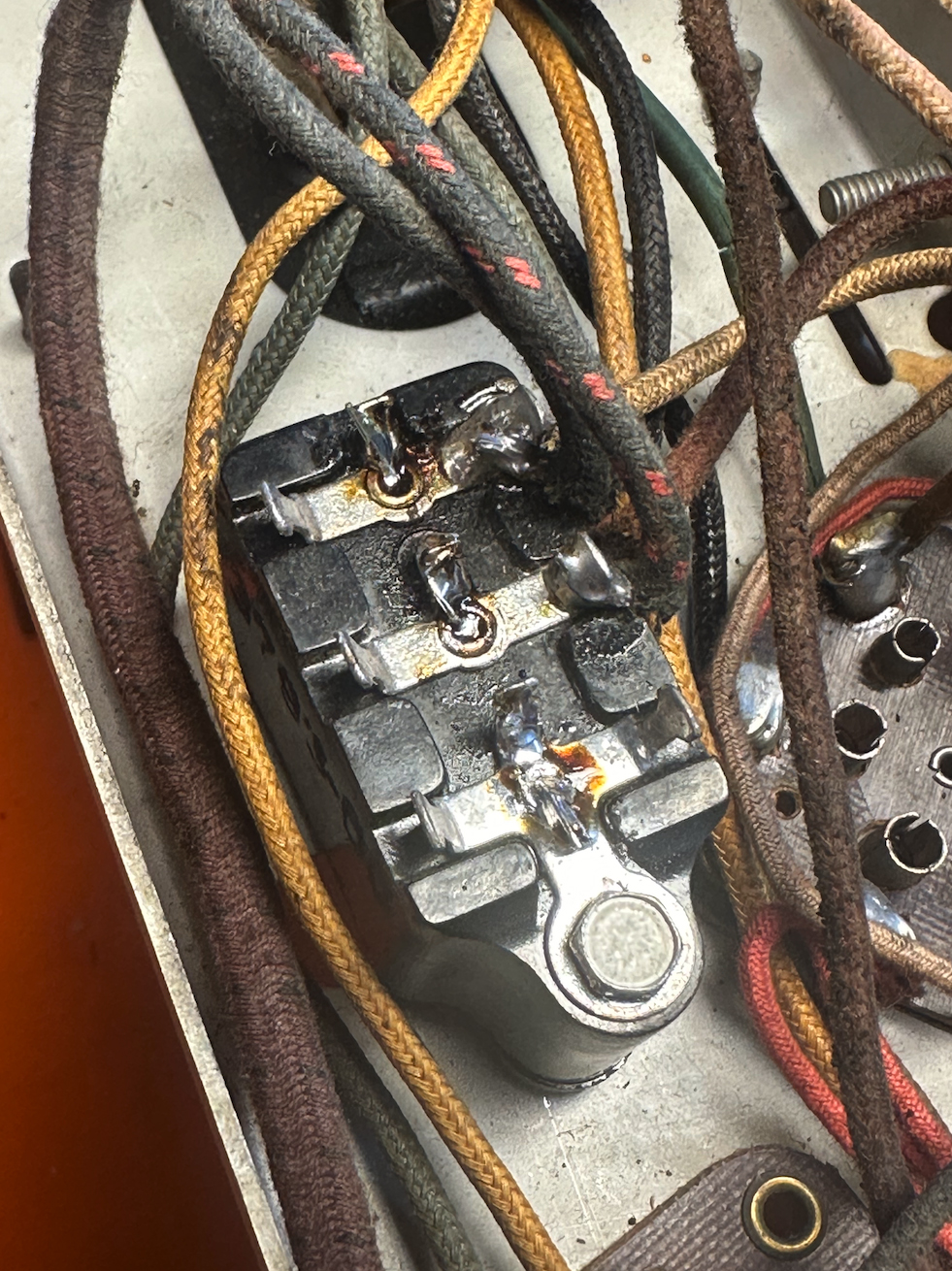
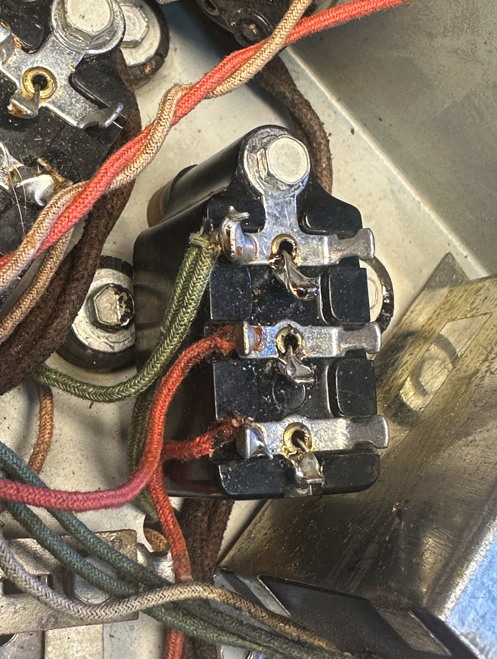
Hopefully I'm on the right track with the other blocks:
Part 23 & 24 are the same value and both go to ground.
Part 26 just has one cap in it, the center is a tie off point.
Part 41 just has one cap in it, the center is a tie off point.
Part 9 is a little less simple with a .0015 and a .05 cap with this strange note: "The .05 mf. section connects the same as condenser 6." Can anyone translate this for me? I see that Part 9 is the .0015 cap in parallel with an 8K resistor to ground so that's pin 2 to 1, should the .0015 cap go from pin 3 to 1? Seems like the only option, are they trying to say that this cap also goes to ground like condenser 6? It's possible I'm overthinking this, just want to be sure.
Part 4 looks pretty simple since the wires are color coded.
The power transformer checks out OK, so does the oscillator coil. Unfortunately the detector/RF coil has an open primary. I've found good instructions on rewinding this coil elsewhere on the phorum so hopefully it'll go smoothly.
I'll probably use 2 watt resistors for the ones that are out of spec. I don't see any ratings on the resistors in the parts list. Resistors 18 and 30 are a little bigger, but maybe that's what 2 watt resistors looked like in the 30s!
I'll look for rubber parts, grill cloth, correct speaker mounting screws and other bits and bobs down the road. Appreciate any insight from people who have tackled one of these before and thanks for this great resource. Glad to be here!
Kurt.
(This post was last modified: 09-13-2024, 02:46 AM by Kurt P.)
Posts: 1,883
Threads: 120
Joined: May 2008
City: Omak
State, Province, Country: WA
Hello Kurt,
Welcome aboard and you have a nice set to start on !
Yes, the bakelite blocks and I too find them fairly easy to do .
I have been working on a Philco off and on in between other projects .
Sincerely Richard
Posts: 1,268
Threads: 11
Joined: Jul 2020
City: Greenlawn
State, Province, Country: NY
Hi Kurt
Welcome to the Philco Phorum. Lots of phriendly pholks (see a pattern here?) who are happy to help. Keep posting on your progress and keep asking questions.
I had commented recently on 2 different Pholks that have acquired Model 89s. Yours is the third. I may be having an experience of deja vu, but my last post involved a guy named Curt or Kurt, also with an 89 missing a speaker. OOh, it's you! A Moderator may combine your threads, as this is the same radio with new info.
Congrats on the work you have done so far. It seems that thank goodness, you are starting with a clean chassis. However, I think that that IF can mounted on the rear of the chassis was someone's "Mod", as it is a chronologically later design than used by Philco at the time of manufacture of your radio. It looks dangerously close to tube socket connections. It also seems that the filter caps were replaced before but may be old enough to want to replace again, especially the blue one under the chassis.
From my previous posts, you will find that this is similar to transformer powered AA5s except for the existence of an RF stage (AA6?) and the troublesome "autodyne" oscillator-mixer as opposed to the "pentagrid convertor" introduced (by RCA?) the same time that this set was designed. Philco used the autodyne oscillator mixer in other models, including the model 80, but the circuit design of the 89 is a little more troublesome. They switched to the 6A7 Pentagrid detector on new designs, but on some sets (such as the successors to the 80Jr.), they stayed with the autodyne circuit.
My notes on another 89 are linked below.
Help understanding a 89 radio rebuild new guy (philcoradio.com)
The correct speaker is a K7 style 8" speaker, Philco P/N 02819, also used on table versions of Models 19, 43 and 71. Field Coil impedance is 1100 Ohm. If you can't find the correct speaker, you can use any 8" speaker with a field coil of about 1100 Ohm or a PM speaker and 1100 Ohm resistor. Any output transformer that was used with a single 41, 42, 2A5, 6F6 or 6K6 output tube and matches the voice coil impedance of the desired speaker can be used. Primary impedance should be about 7K Ohm.
RE parts 8,9 and 6, they should all be in the same block. One end of caps 6 and 9 and one end of resistor 8 should be connected to ground through the end terminal if this block with the ring terminal integrated to it. Make sure that good clean uncorroded star washers are in place on this terminal. when remounting the block. Cap 6 is a 0.05uF B+ bypass cap, whose other end connects to the middle pin of the block. A 0.047uf cap will suffice here. Resistor 8 and cap 9 are paralleled and are in series with the oscillator tickler coil and supply cathode bias. These parts connect to the remaining end terminal. Please note that there were many upgrades to this circuit and the current values are 8KOhm for resistor 8 and 1500pF (0.00015uF) for Cap 9. Best to use 2 700pF Mica caps here. Please note that to confuse things more, the numbering convention in the diagram posted in the Philco Library is different from that of the Nostalgia Air diagram. This is because these are different Code numbers using different tubes for the 1st detector. Please ensure that your set uses the '77 1st detector (autodyne oscillator-mixer) tube as the numbering and values for sets using the '36 1st detector are different. Please also note that the '77 1st detector is more stable than the earlier '36 detector.
There are articles in the Philco Library (part of this Phorum) that describe all of the changes in the various versions of the 89. The Nostalgia Air diagram lists several modifications to the original circuit having to do with insulators for trimmer caps and a revised tuning cap. My guess is that your radio, having the later '77 1st detector, has the mods described in the Nostalgia Air document
The Philco Library document "evolution for the Model 89 is linked below:
Evolution of Philco Model 89 – Philco Library (philcoradio.com)
If you can connect a speaker, you can still test the set even with the dead RF to 1st detector coil primary. Just touch a 10-20 ft wire to the grid cap of the 1st detector. If you can pick up a station, then the 1st detector appears to be working. This is a very good sign. Note that because of the low IF frequency, it is likely that you will pick up a strong station on more than one location on the dial.
So in summation: - I think that you have a later version of the Code 123, that uses a '77 detector. If so, this is a bonus, as the '77 1st detector is much more stable than the '36 1st detector, and other service and factory mods are likely completed.
- If you can't find the right speaker, use any 8" speaker with an output transformer with a 7KOhm primary and secondary that matches the speaker voice coil impedance. The field coil should be about 1.1KOhm. If using a PM speaker, use a 1.1K resistor and upsize Caps 44 and 46 to at least 20 uF
- Resistor 8 and Caps 6 and 9 are in the same block. One end of all 3 components connects to the end lug that is grounded. The other end of cap 6 (0.05uF) goes to the middle lug. The other ends of the 1400pF cap 9 and 8KOhm resistor 8 go to the remaining terminal.
- The IF Can that likely hides a coil is likely an add-on. Make sure that it does not short to tube sockets if left in.
Hope this all helps!
"Do Justly, love Mercy and walk humbly with your God"- Micah 6:8
"Let us begin to do good"- St. Francis
Best Regards,
MrFixr55
Posts: 11
Threads: 2
Joined: Aug 2024
City: Orange
State, Province, Country: CA
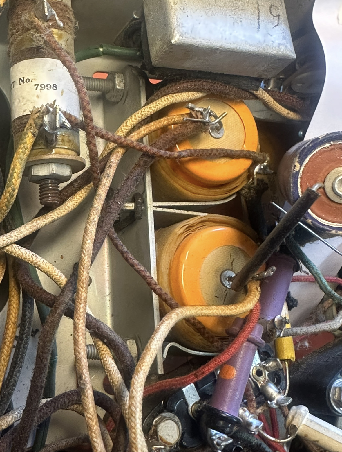
Progress continues, finished blocks 9 and 26. I wonder for caps 23 and 24—can I get away with 100pf instead of 110pf?
Also, I looked through the phorum but didn't see any discussion of filter cap mounting. I have two small 8uf caps—way too small to fit in the original location where the orange replacement caps are currently. Normally I'd drill a hole and mount a terminal tie strip but there are a lot of wires in here and I don't want to make a mistake and create more work for myself. Curious what solutions have been tried before...
Thanks!
Kurt.
Posts: 7,303
Threads: 269
Joined: Dec 2009
City: Roslyn Pa
Yup your fine w/a couple of 100mmfd caps.
On 37 & 38 I'd dig up a Twist-Loc cap w/two + terminals. Cut it open and mount the two 10mfd caps inside. - tie together and connected to one of the - lugs. You must use an insulator as the - is not the chassis gnd. Connect the + to the + terminals on the cap. To mount it you'll have to slip it up from the bottom of the chassis, the flared end of the cap won't clear the hole from the top.
https://philcoradio.com/library/download...20146B.pdf
When my pals were reading comic books
I was down in the basement in my dad's
workshop. Perusing his Sam's Photofoacts
Vol 1-50 admiring the old set and trying to
figure out what all those squiggly meant.
Circa 1966
Now I think I've got!
Terry
(This post was last modified: 09-23-2024, 09:57 PM by Radioroslyn.)
Posts: 1,268
Threads: 11
Joined: Jul 2020
City: Greenlawn
State, Province, Country: NY
Hi Curt,
Congrats on your progress so far.
+1 on Terry's Advice. The original caps were likely "wet" electrolytics. Like Terry said, the negative terminals of Caps 37 and 38 don't go to ground, they go to the center tap of the power transformer HV winding. That blue cap likely parallels one of the yellow Sprague jobs and does not need to be added. Remember, if the speaker is being replaced by one without a field coil, you will want to up the value of the capacitors to 20uF, or maybe 30 uF.
There are a couple of ways to go here, all electronically correct. What technique you use depends on how original you want the chassis to look.
- The Restored Look- Obtain 2 original caps from a junk set of the vintage or post a wanted ad in the Phorum. Follow the instructions in "Restoration Tips" for stuffing electrolytics.
- Alternate Restored Look- Obtain 8" of 1"OD copper tubing and 2 1" copper tubing caps from a plumbing supply, Home Depot or Lowes. Cut in half with a pipe cutter or have the plumbing supply cut them in half. Mount in the brackets where the 2 Spragues are, either with fish paper or a layer of electrical tape between the bracket and tubing. From the underside, place the new caps inside each of the pieces of tubing with suitable insulation or RTV to hold in place. A 1" rubber cap or stopper can be used to close the bottom holes if desired. Put holes in this cap to pass the capacitor leads. Since you will not be able to see the capacitor markings when they are in the copper tubings, color code the leads on the capacitors with marker, heat shrink tubing or wire insulation. It is not necessary to actually solder the negative terminal of the capacitor to the body of the copper tube unless actually desired to do so, however, the negative lead of the capacitors must be correctly connected electrically per the schematic. Bend "eyes" onto the end of the leads of each capacitor. Transfer the wires from the Sprague caps to the new caps one at a time. Place the copper caps on top of the copper tubes. These "capacitors" will look a lot like Marshon electrolytic capacitors.
- The quick and dirty- Obtain a terminal strip with at least 3 non-grounded lugs and a mounting lug near the center of the strip. This lug will be used only to mount the strip. do not connect any wires to this lug. Install the capacitors onto the strip. The negative terminals of the capacitor should go to the same lug, toward the center of the strip. The 2 positive terminals should point towards the ends of the strip. Transfer the wires one by one from the leads of the existing capacitors to the terminal strip, observing the same polarity.
Hope this helps.
"Do Justly, love Mercy and walk humbly with your God"- Micah 6:8
"Let us begin to do good"- St. Francis
Best Regards,
MrFixr55
Posts: 7,303
Threads: 269
Joined: Dec 2009
City: Roslyn Pa
Now that I've been thinking about it somewhere I saw a replacement made using a section of pvc pipe and a cap to cover the top. The bottom was circular piece of wood I think. Was painted w/copper hammertone and look pretty good. Certainly, less expensive than copper.
When my pals were reading comic books
I was down in the basement in my dad's
workshop. Perusing his Sam's Photofoacts
Vol 1-50 admiring the old set and trying to
figure out what all those squiggly meant.
Circa 1966
Now I think I've got!
Terry
Posts: 1,268
Threads: 11
Joined: Jul 2020
City: Greenlawn
State, Province, Country: NY
Or you can do what Terry suggests. Thx Terry for remembering that. A lot cheaper. I remember an article about that, but couldn't remember if they covered it with paper, painted it aluminum or what. Yes, it's cheaper and easier to work with, however, since I have the plumbing tools, for me, it's easy. Also easy to have the store cut the stuff for you. An advantage about the PVC is that it acts as an insulator also. Probably best to use electrical grade. Only issue is that the OD of the cap is bigger. Can't remember if the author of that article cut the cap down on a lathe. I thought that the copper would look cool and do not know what 8" of 1" copper tubing goes for now.
If you are looking for functionality, want the empty bracket space filled and don't care if they actually look like capacitors but want the spaces filled, then using PVC is a great way to mount the new electrolytics. Paint is optional
My GE S-22A (RCA R-7A) has Marshons, and I think that they are cool. Since that chassis is extremely shielded, I didn't bother hollowing them out, I left them in place, cut the wires to them and added electrolytics under the chassis.
"Do Justly, love Mercy and walk humbly with your God"- Micah 6:8
"Let us begin to do good"- St. Francis
Best Regards,
MrFixr55
Posts: 7,303
Threads: 269
Joined: Dec 2009
City: Roslyn Pa
I did some nosing around and found that the original caps were 4 3/4" long x 1 5/16" in dia. Guess what 1" pvc pipe fits the bill at 1.315" od. Sometimes you can find some short pieces at the store for cheep. A good sanding to breakdown the slick finish on the outside will help the silver paint stick. Primer helps even more it's made for pvc stuff. A couple of end caps and something for the bottom. You could use hot glue to hold it in place (the bottom cap). That's if you want to go this route...
The last time Mershon caps were used in Philco chassis was in the 1931/32. So, you wouldn't really find copper caps in the 89/19 models. For what it's worth.
When my pals were reading comic books
I was down in the basement in my dad's
workshop. Perusing his Sam's Photofoacts
Vol 1-50 admiring the old set and trying to
figure out what all those squiggly meant.
Circa 1966
Now I think I've got!
Terry
(This post was last modified: 09-25-2024, 10:40 AM by Radioroslyn.)
Posts: 11
Threads: 2
Joined: Aug 2024
City: Orange
State, Province, Country: CA
Hi all and thanks for the great responses! I went with a can left over from another radio, kinda scratched up but it does the job:
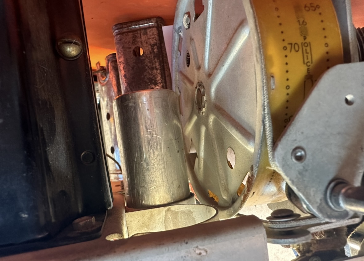
Looks a little worse underneath but that's OK. I'm completely out of wire and added a couple of pieces of 14 gauge wire temporarily so I know where the speaker connections will go. Might have to redo it eventually if I can't find an original speaker since I'll need those bigger caps. There's an original on eBay but it isn't cheap!
A couple of other questions. Does anyone know what #4 is on this schematic?
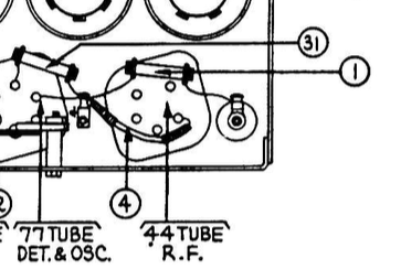
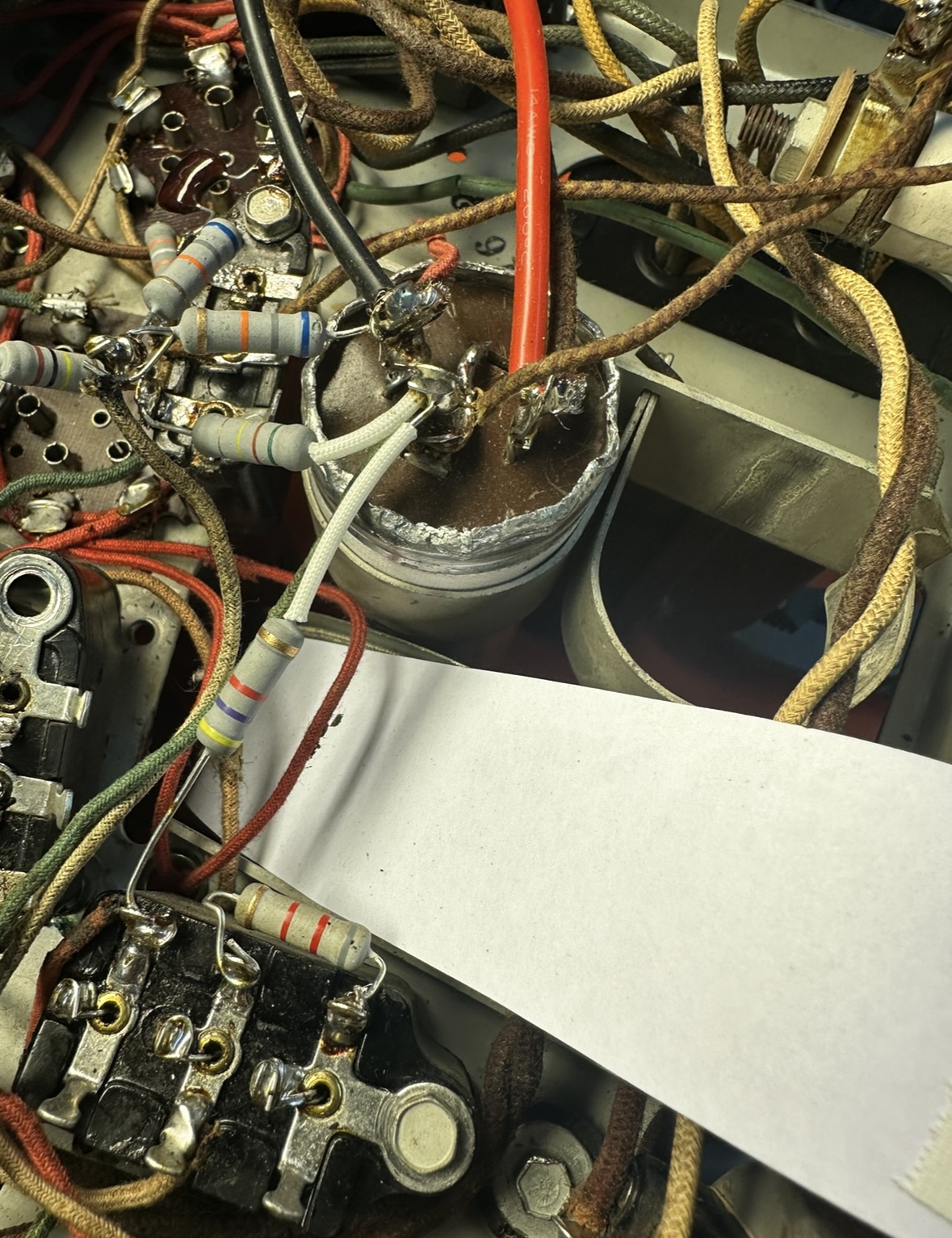
The schematic makes it sound like it's part of the box of 5 caps going to ground but I think that's a mistake. The markings make me think it's a resistor, it has an orange body:
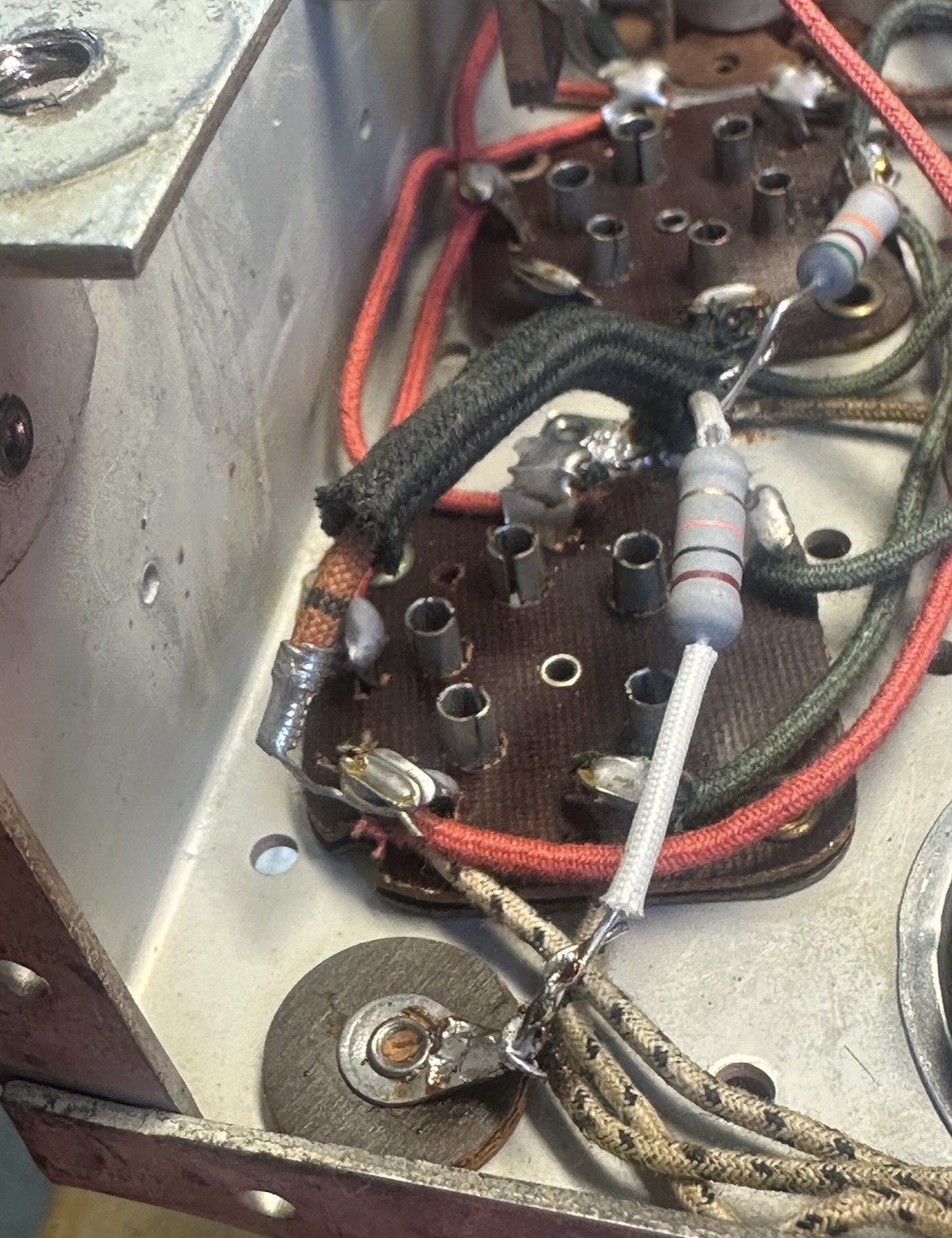
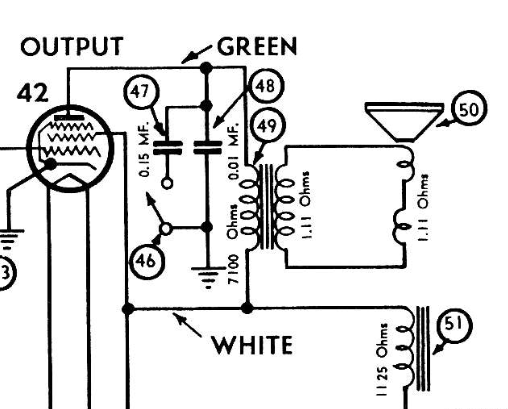
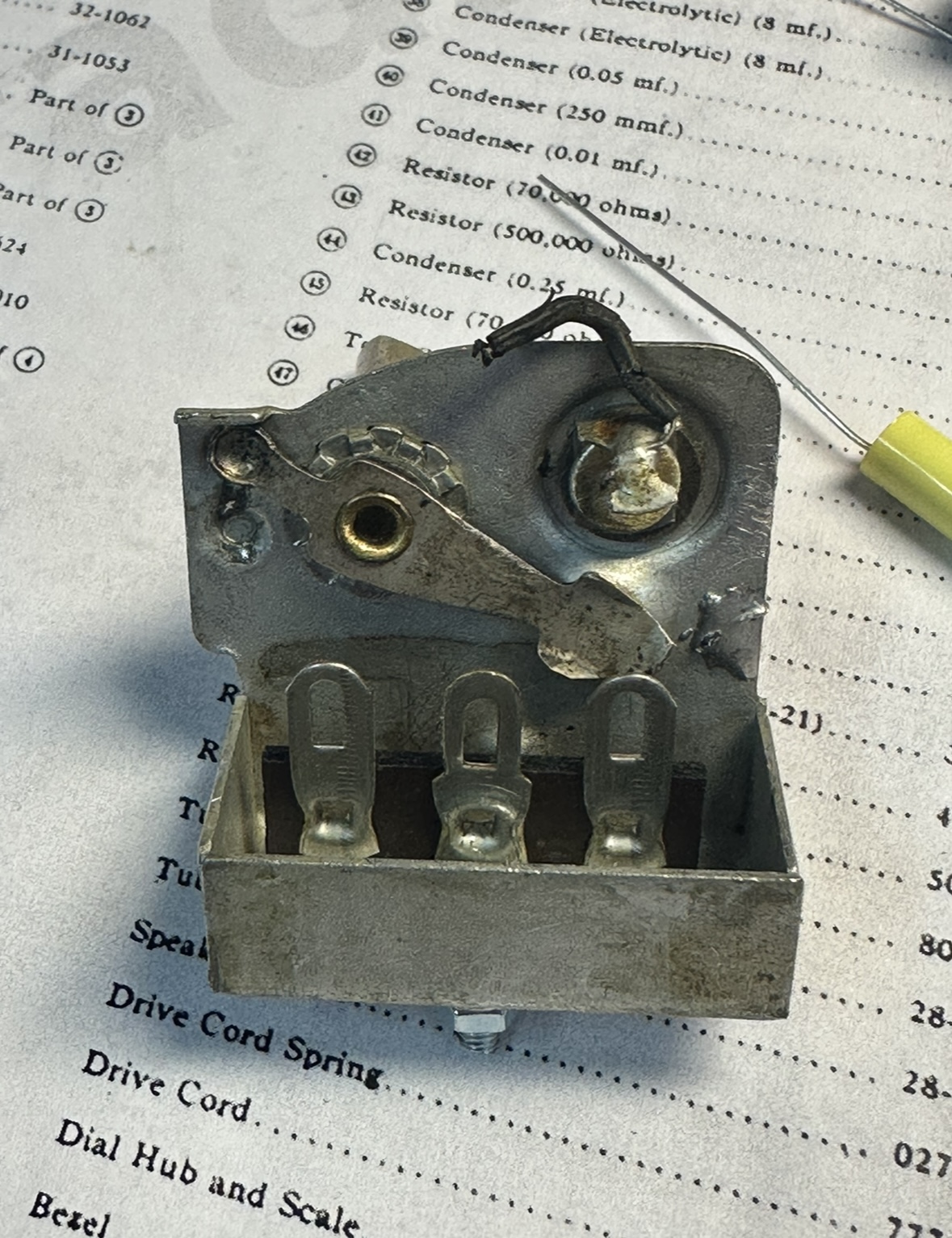
Lastly (for now) I'm working on the tone caps. Am I correct in thinking 48 is always going to ground and the switch adds 47 in parallel? Seems right, just want to be sure...
Mounted a terminal tie strip inside for the caps, done with the bakelite boxes!
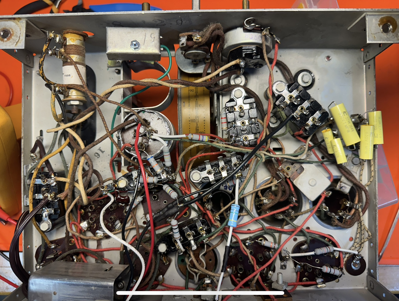
Next I'll work on the RF coil when my coil wire comes in the mail. Thanks again!
Posts: 7,303
Threads: 269
Joined: Dec 2009
City: Roslyn Pa
Yup you can also play w/the value of 48. I usually make it a little smaller this will make the sound a bit brighter. Something like a .005 or 006 @630v.
When my pals were reading comic books
I was down in the basement in my dad's
workshop. Perusing his Sam's Photofoacts
Vol 1-50 admiring the old set and trying to
figure out what all those squiggly meant.
Circa 1966
Now I think I've got!
Terry
Posts: 1,268
Threads: 11
Joined: Jul 2020
City: Greenlawn
State, Province, Country: NY
Yes, 48 is a bypass cap always in place. Important because it also has a role in cutting down on parasitic oscillation. There may be a mistake in the value for #47. I think that it should be a 0.015 uF cap, not a 0.15uF. That would cut off too much treble with the tone control in the low position.
#4 on your pic is a 300 Ohm wirewound resistor that serves as the cathode bias resistor for the 44 RF and 44 IF tubes. There is a numbering mistake on the pictorial. The resistor should be labeled as #5.
According to the schematic, #5 is this 300 Ohm resistor and #4 is the multi-capacitor can. The cap that is shown as #4 on the schematic that parallels that resistor is listed as 0.09uF. A 0.1uf cap will do fine here. If the resistor is out of spec, a 300 Ohm1 Watt or 2 Watt resistor should do fine. I don't know why they used this type flexible wirewound resistor. It could be for space considerations or adding inductance because it was wirewound.
These multi-caps were an effort at streamlining assembly, as all of these caps are "bypass" caps, where one end connects to chassis ground and a wire for each individual cap goes to either a cathode resistor or a voltage divider that supplies a plate or screen voltage. These were easier to assemble and wire into the circuit than 5 individual caps. This was also the theory behind the bakelite blocks that Philco used. If one of these bypass caps was left out, oscillation or "motorboating (low freq oscillation) could occur.
BTW, the underside of the chassis, wiring, the tuner drum, etc. is in fantastic condition given its age. I have rarely seen coloring on cloth covered wire this nice on any set I own or have worked on, with the exception of a GE S-22A (RCA R7A), Ca 1931, that came from Utah, likely from a smoke free home.
"Do Justly, love Mercy and walk humbly with your God"- Micah 6:8
"Let us begin to do good"- St. Francis
Best Regards,
MrFixr55
Posts: 11
Threads: 2
Joined: Aug 2024
City: Orange
State, Province, Country: CA
Back to working on this, pretty much everything is done minus the RF coil, which I'm putting off until last. Thanks for the tips on the tone control, it's in place and ready to go. This is a very clean chassis, the only rubber wire in this set went to the tone control, happy to only have to replace one. Installed a fuse, almost ready for a test power up:
Got a replacement speaker off eBay, it arrived a little greener than I expected, probably verdigris:
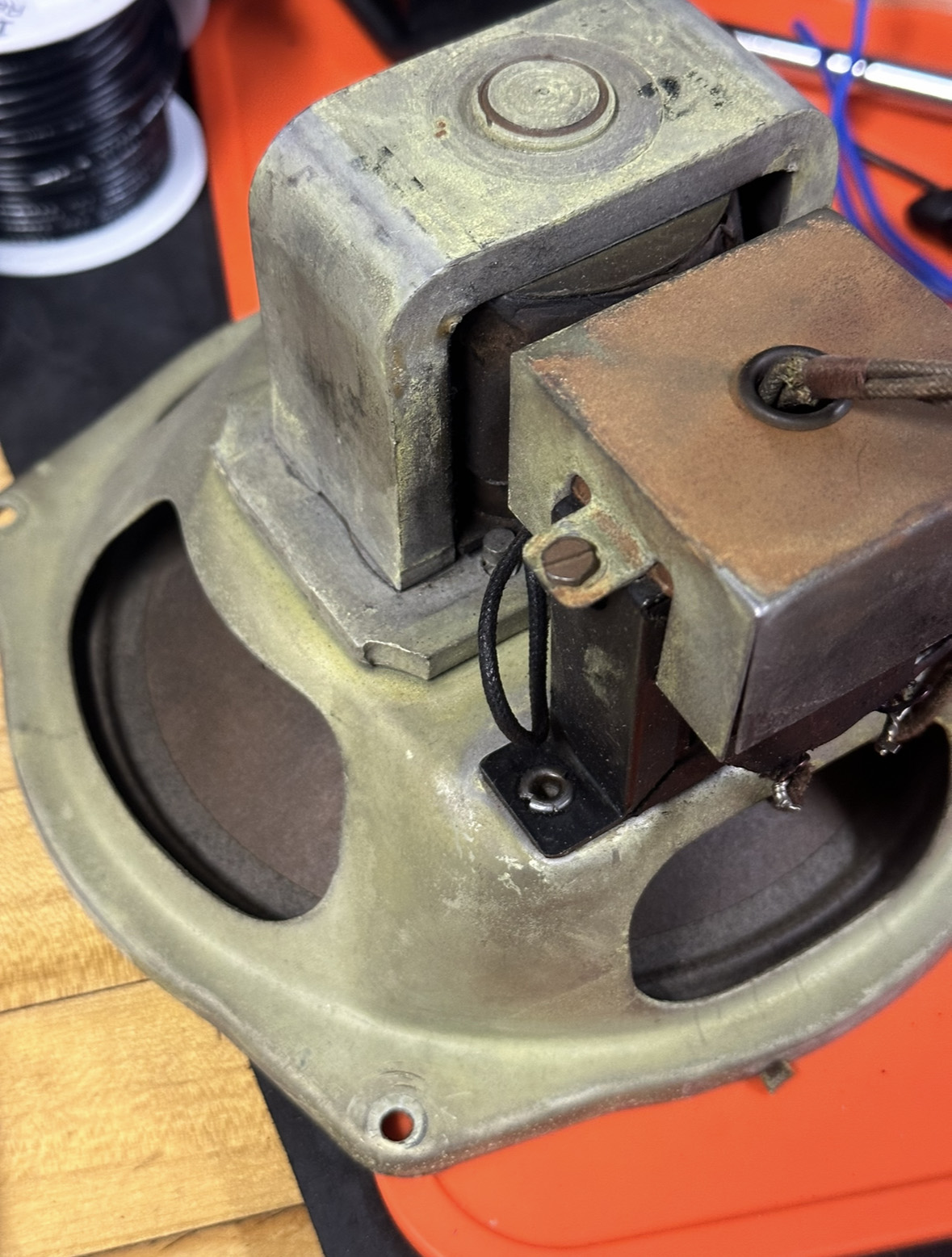
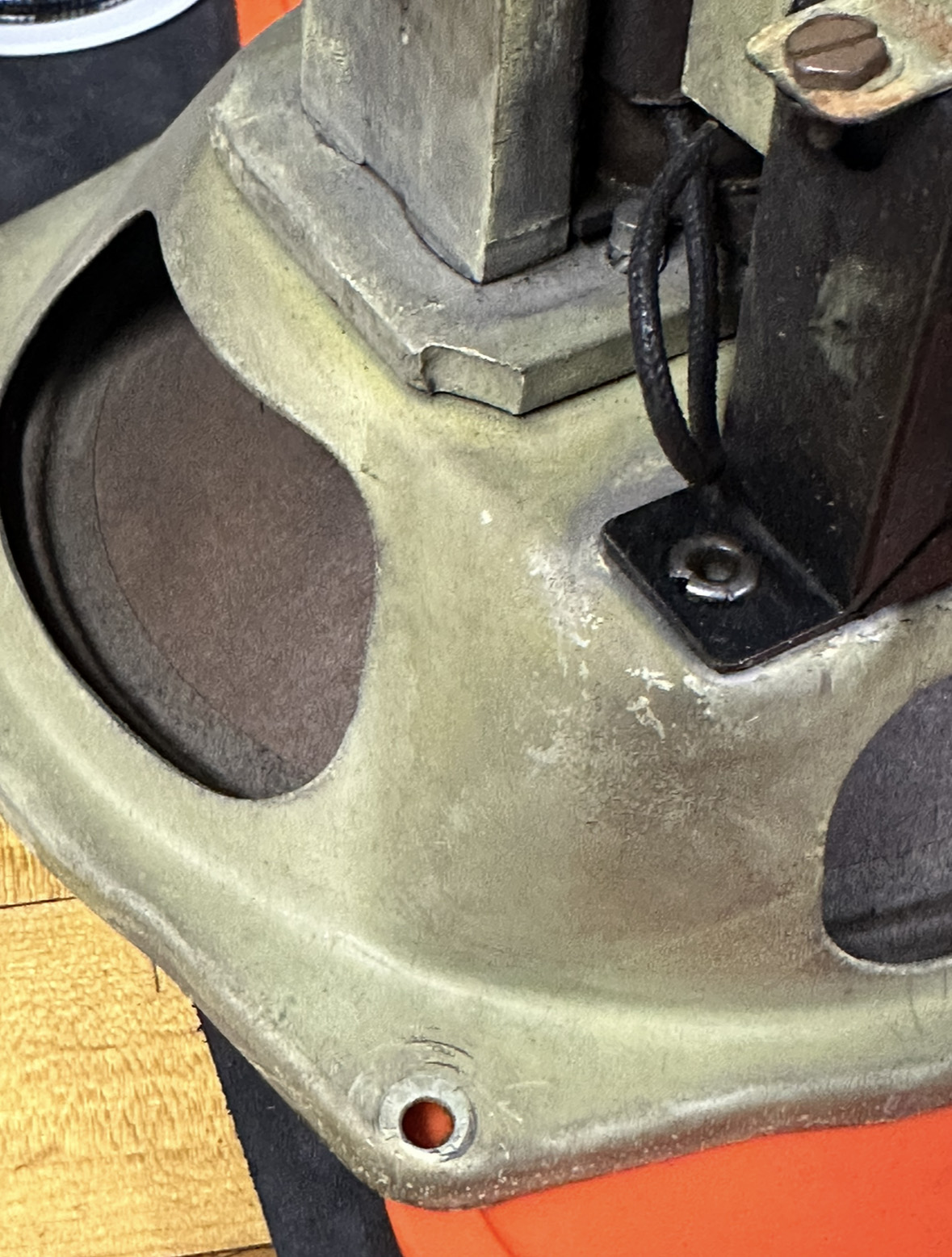
Came off in no time with a little Naval Jelly:
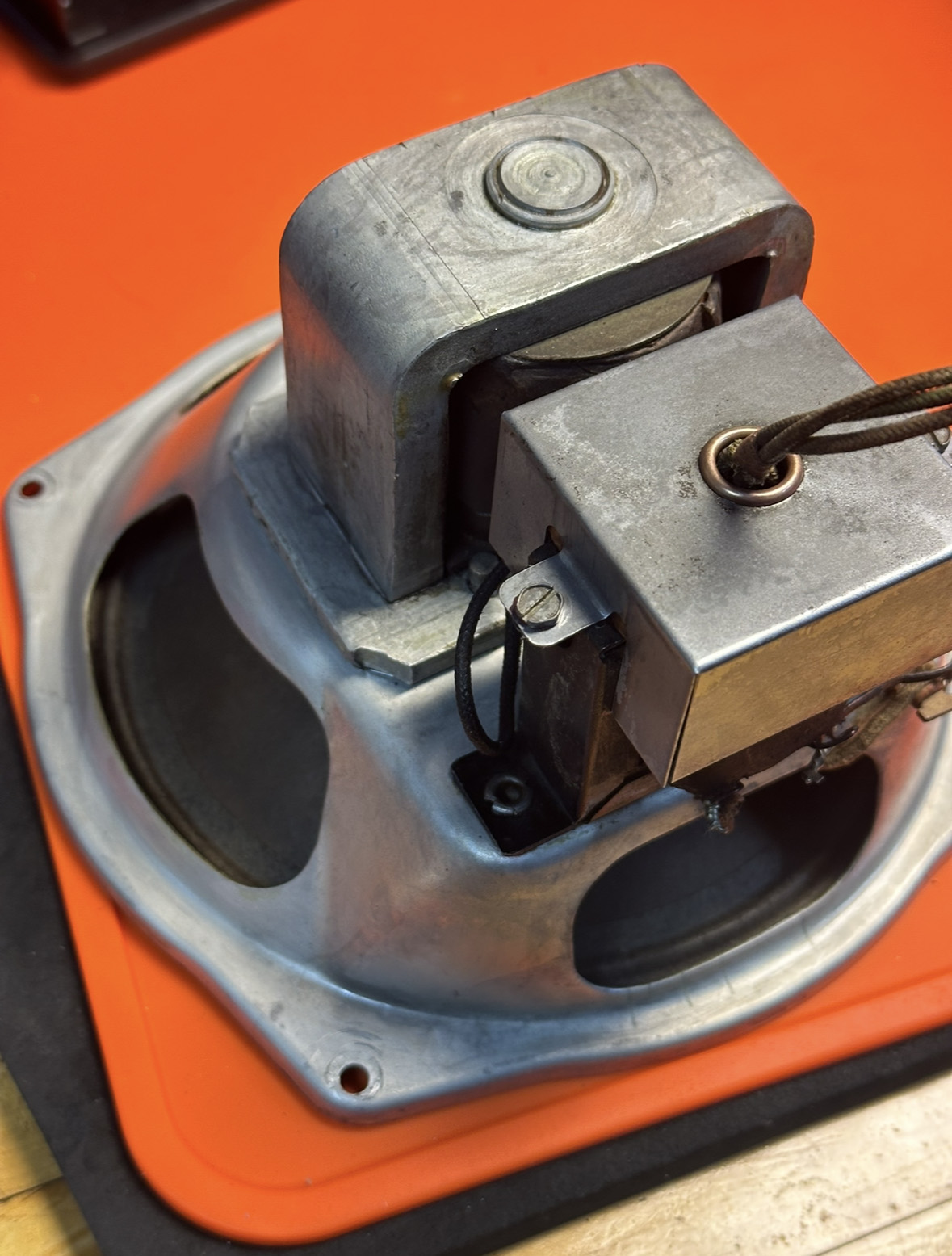
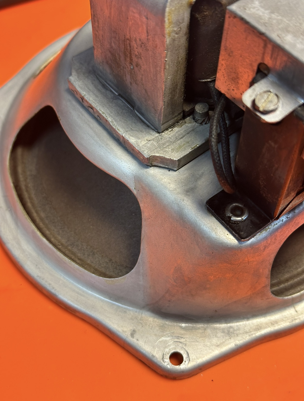
The wires in the replacement speaker were in good shape, too, enough that I could still read the colors. Hopefully 18 gauge stranded will be thick enough to replace it with, the wire that was in there was a little thicker but it looks like most of that was the cloth. Next I'll connect that speaker, bring it up slowly and hope for filament glow!
Posts: 11
Threads: 2
Joined: Aug 2024
City: Orange
State, Province, Country: CA
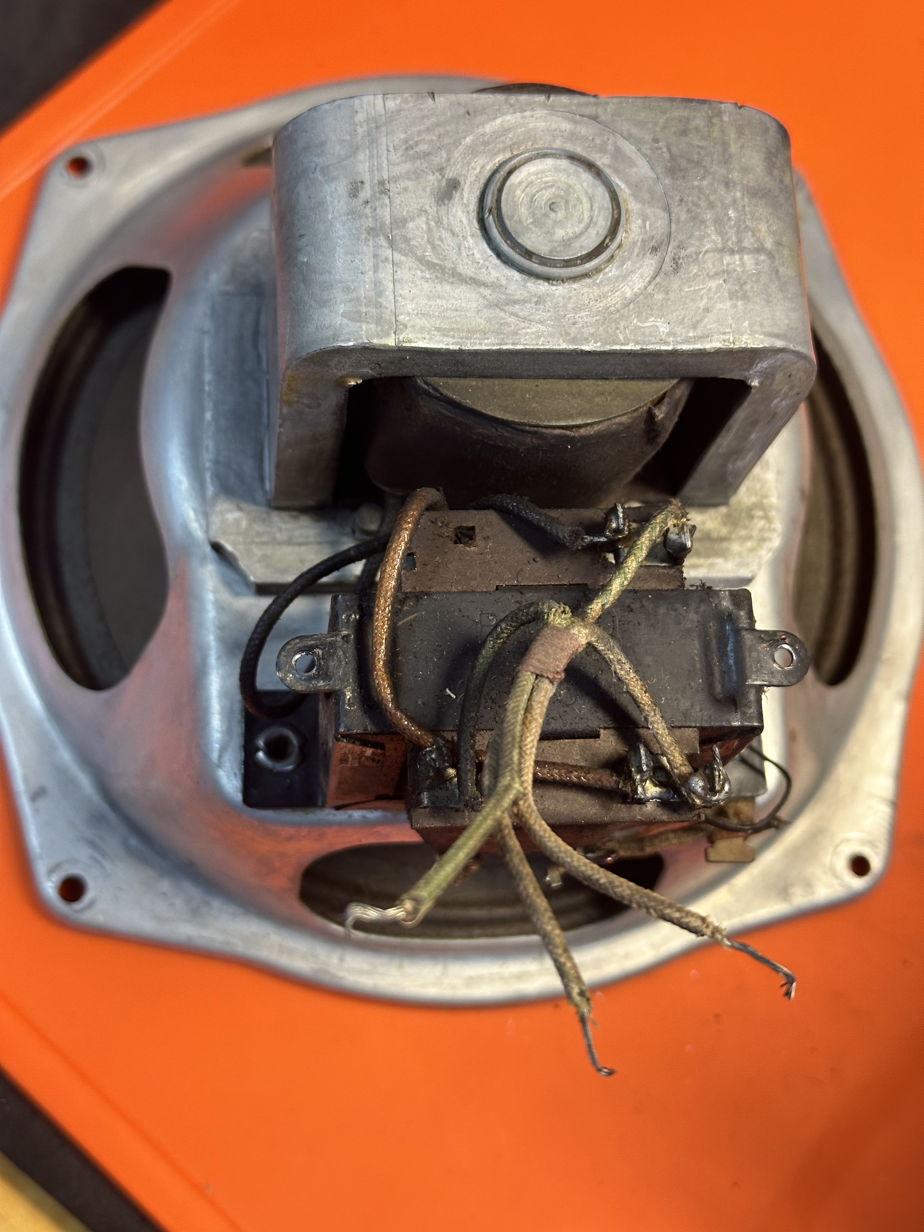
Well it looks like I jumped the gun.  Brought it up slowly on a variac and at about 30V it was drawing .24A and at 60V it was drawing about half an amp. Shut it off and took a closer look at the speaker/OT, supposedly from another 89. Turns out it's stamped on the OT 2580-P. Not sure about the "P" designation but according to docs on this site it should work with a 42 output tube so that should be good. This is my first field coil/OT so I'm not sure the best way to test it. DC resistance readings (disconnected from the radio) are as follows:
Green — White (OT primary) 460Ω
Green — Green & White (OT Primary and field coil) 1.6KΩ
White — Green & White (field coil) 1.13KΩ
That sounds about right.
I'm not sure what the two flat wires coming out of the bottom of the FC are, but I think the two at the bottom of the OT are the secondary. Unfortunately both pairs seem to be shorted, but again I'm not sure exactly what readings to expect on the secondaries. I think the schematic shows the speaker connected to the OT secondary only, it looks like this speaker shares connections with the FC. Maybe this is from another 89 model? 
The speaker itself moves well without binding and pops and moves a little the way I expect with a AA battery across the terminals. I've attached pictures below. Any help would be appreciated! Also, I haven't rewound the RF coild primary yet, hopefully that doesn't play a part here... Thanks!
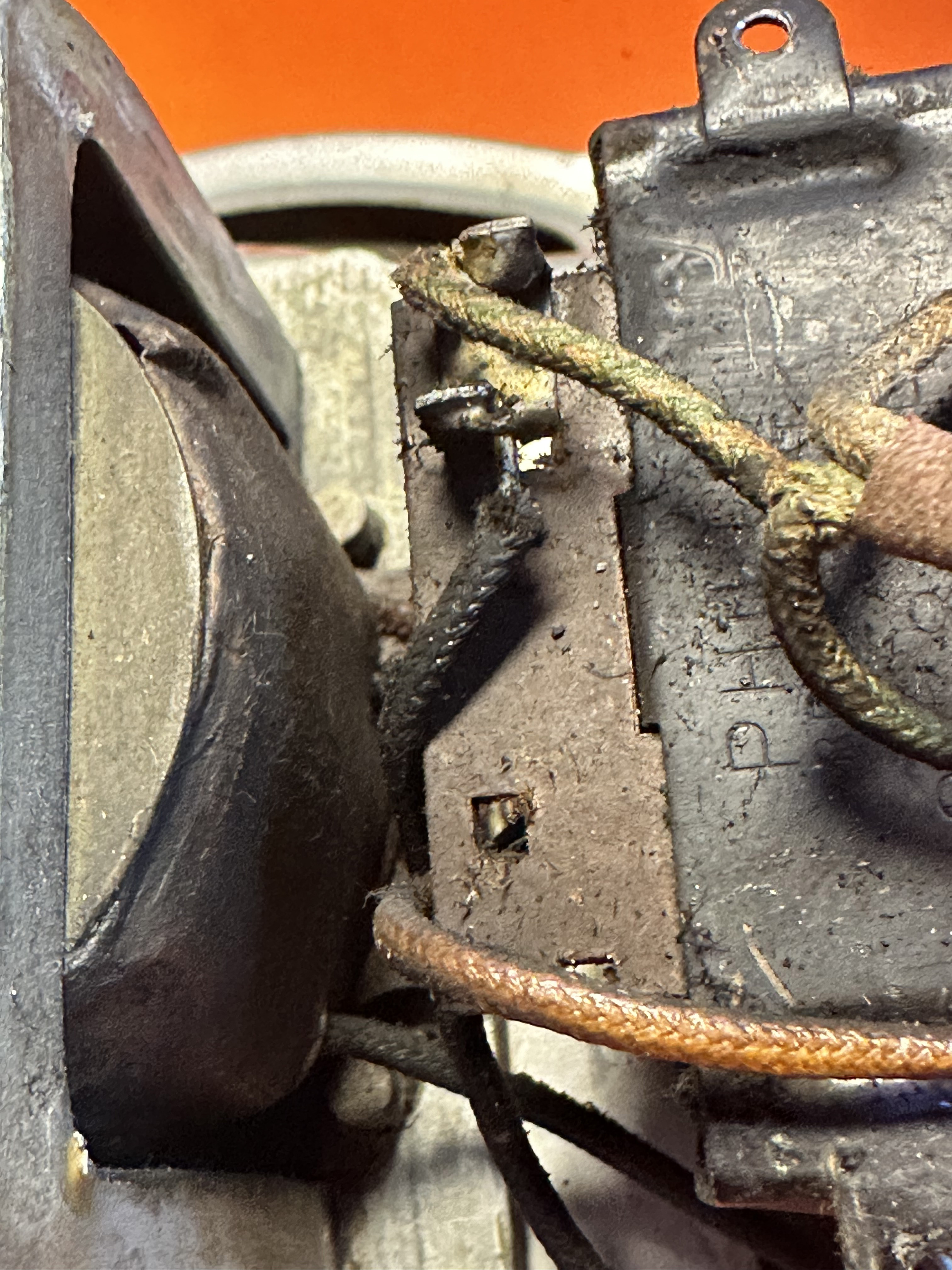
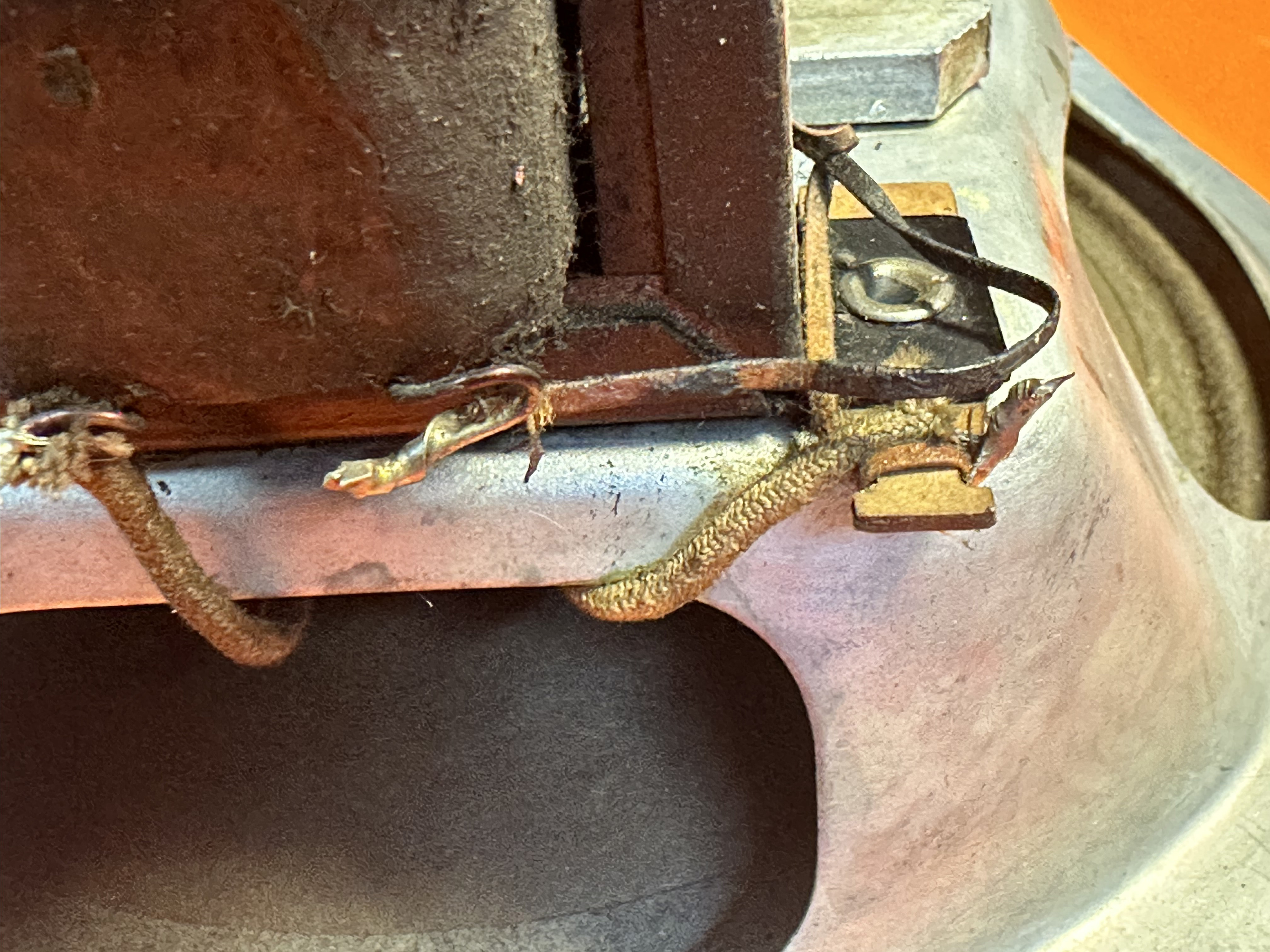
(This post was last modified: 10-18-2024, 01:39 PM by Kurt P.)
Posts: 1,151
Threads: 47
Joined: Feb 2015
City: Roseville, MN
I may be incorrect but you should measure around few ohms for the voice coil. In addition you may have a hum bucking coil which also would measure around one ohm. The OT primary will be 600 up to 2k and secondary 1 to 3 ohms. FC will be around 1200 ohms.
One lead from the OT primary may be connected to one lead of the field coil as this is the B+ supply from the field coil to 42 plate through the OT primary. Check the schematic for correct wiring.
Users browsing this thread: 1 Guest(s)
|
|
Recent Posts
|
|
Model 80 Antenna Issue?
|
| Thanks Gary and Rod.
I also found an article in the Philco Repair Bench under Service Hints and Tips, about installi...Hamilton — 12:32 PM |
|
Model 80 Antenna Issue?
|
| Hello Hamilton, here is a little information found in our Philco Radio Library at the bottom of the Home page. Hope it ...GarySP — 11:28 AM |
|
Model 80 Antenna Issue?
|
| I did as you suggested and touching the middle of the volume control did nothing so the coil has to be rewound. Any idea...Hamilton — 10:19 AM |
|
1949 Motorola 5A9M
|
| This would be the second portable in the "other radios" forum where I have a similar one in my collection. I h...Arran — 12:41 AM |
|
Looking for any info: 1977 Ford-Philco Console Hi-Fi Turntable and Radio
|
| Hi PittsburgTost.
The record changer looks like a Garrard or BSR (Likely Garrard). The spindles just pull out and pu...MrFixr55 — 11:57 PM |
|
Looking for any info: 1977 Ford-Philco Console Hi-Fi Turntable and Radio
|
| Hello PittsburghToast ,
Welcome aboard and it looks like gary may have something for you !
now if I dig through my se...radiorich — 11:35 PM |
|
Model 80 Antenna Issue?
|
| You are kind of on the right path. You can touch the grid cap of the Detector/Oscillator 36 tube. I'm expecting a respon...RodB — 08:48 PM |
|
Looking for any info: 1977 Ford-Philco Console Hi-Fi Turntable and Radio
|
| Welcome to the Phorum, PittsburghToast! I found an old thread that my interest you regarding the quality and worth of P...GarySP — 08:48 PM |
|
Looking for any info: 1977 Ford-Philco Console Hi-Fi Turntable and Radio
|
| Welcome to the Phorum!
:wave:
We do not have anything on that unit in our digital library. There is a Sam's Photof...klondike98 — 08:47 PM |
|
Model 80 Antenna Issue?
|
|
I’ve replaced all the caps and resistors and the radio is working but minimal volume unless I put my hand near the re...Hamilton — 08:24 PM |
|
Who's Online
|
| There are currently no members online. |

|
 
|


![[-] [-]](https://philcoradio.com/phorum/images/bootbb/collapse.png)


