12-19-2024, 01:31 PM
With my recent power amp work going on, I felt I needed a good solid preamp. Again, trying to keep costs down and function up. I've been using a couple of these lately as they do about everything I need to do. The subject at hand was my "test" amp and I'd been using it for several years. But is is sounding lackluster and drab. I did find part of it was my lousy cheap portable CD player, but even with a good rack CD player, it still sounded dull. So, it is time to see if I can liven it up back to where it should be! I ordered a handful of caps from AES and finally got it on the bench.
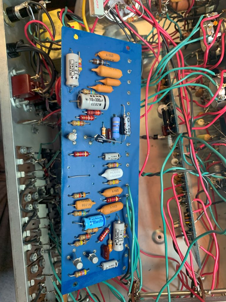
It wasn't easy, but it wasn't bad either. The PC boards made it a lot easier to unsolder and replace the old caps. In my pictures, you will note I've replaced one transistor with a heat sink on it. That is Q4, the output transistor. They were originally a larger round thing with a heat sink, but they get weak and make static. I spent hours trying to track down the source of that static, resoldered, replaced resistors, scoped and finally tracked it down those transistors. After a little research, I found parts at: https://www.updatemydynaco.com/ This fixed the problem. Parts are very affordable and shipping is very prompt. He also has the complete recap kits too, but I ordered mine with other parts from AES. I did NOT replace the main filter can cap. I didn't see any issues with it at this point, and it's very easy to get to when that time comes. Ill let the pictures speak for themselves.
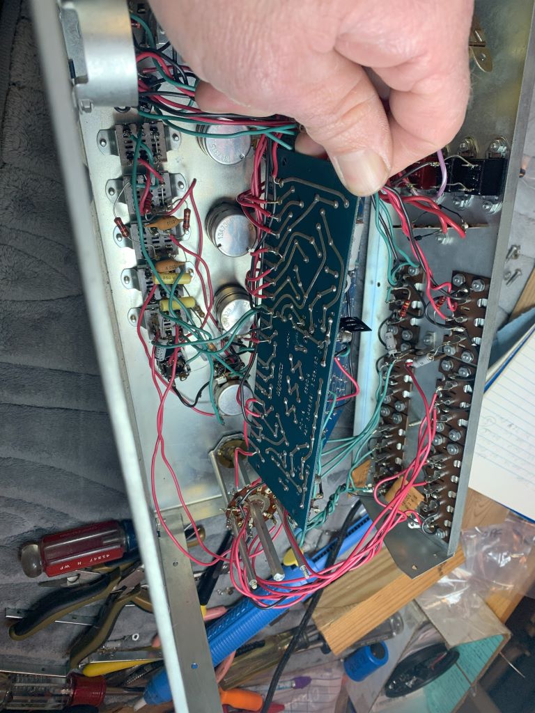
A few notes: I pulled the rear of the chassis, PC board brackets, power trans & filter can. I tried to pull the selector switch, but the knob screw was rather find if it's place, so I just pulled the rearmost wafer switch. Be careful if you follow suit. They're delicate, and there's a small fibre washer that's easy to miss. The rear PC board was fairly easy to flip up and get to the connections, the front one - not so easy, and is why I pulled all the previous. This allows you just enough room to flip things into a figure 8 and get to your solder joints, Take pictures and mark your - on your caps. I only replaced the electolytics, There's plenty of sources for schematics and service info on the 'net. I also replaced the output caps on the front panel (for headphones). The rest, I left alone. Just keep track of your washers, nuts and screws. There's no labeling on the PC boards either, so one piece at a time. Also, keep the soldering heat minimal because it is easy to lift the traces.
Tied my PC boards in a figure 8
All those old caps. They should have lasted more than 50 years!
Thought this was interesting.
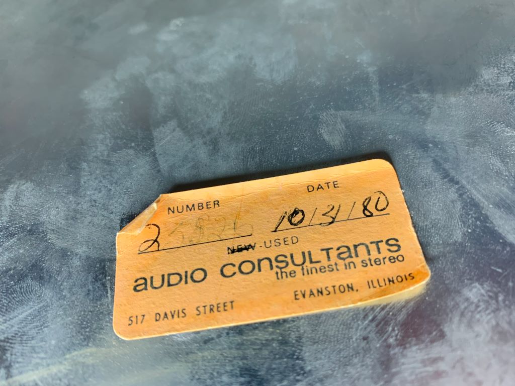
And this.
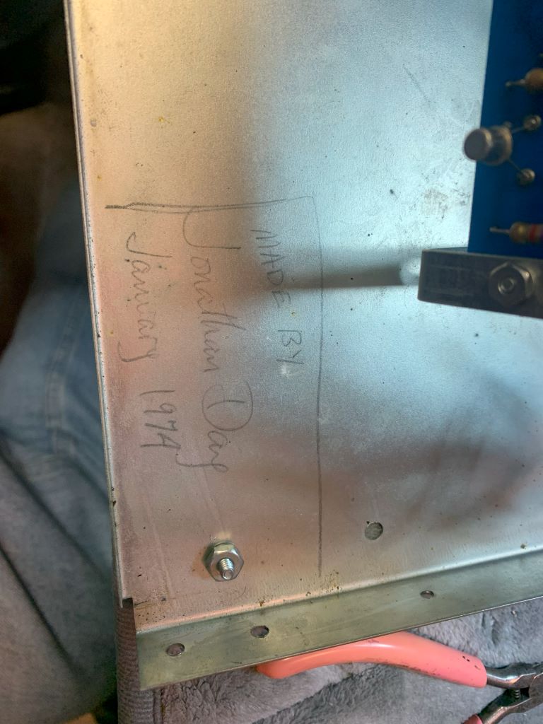
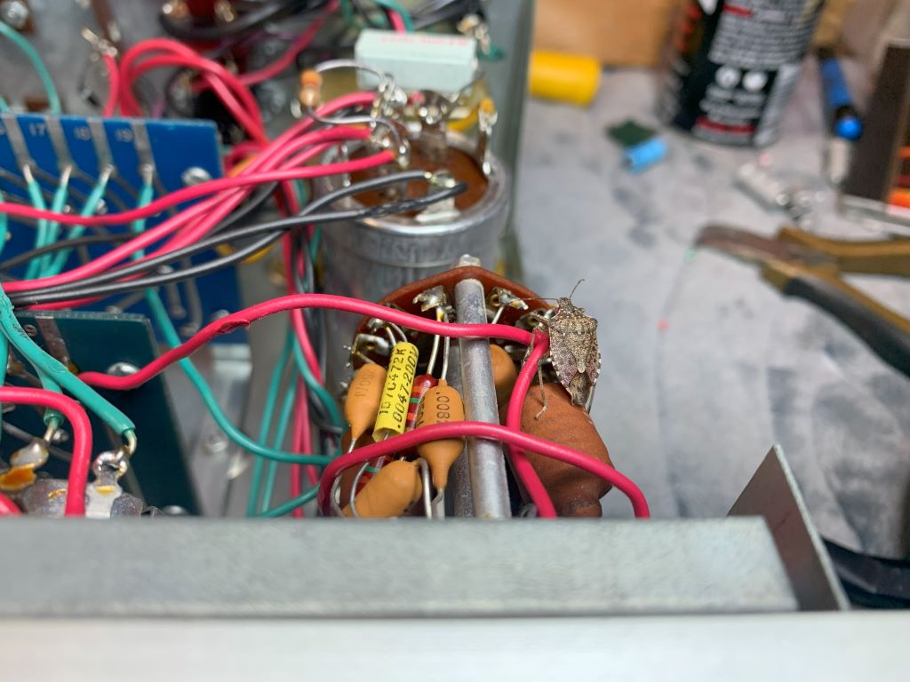
Just trying to get the "bugs" worked out!
It wasn't easy, but it wasn't bad either. The PC boards made it a lot easier to unsolder and replace the old caps. In my pictures, you will note I've replaced one transistor with a heat sink on it. That is Q4, the output transistor. They were originally a larger round thing with a heat sink, but they get weak and make static. I spent hours trying to track down the source of that static, resoldered, replaced resistors, scoped and finally tracked it down those transistors. After a little research, I found parts at: https://www.updatemydynaco.com/ This fixed the problem. Parts are very affordable and shipping is very prompt. He also has the complete recap kits too, but I ordered mine with other parts from AES. I did NOT replace the main filter can cap. I didn't see any issues with it at this point, and it's very easy to get to when that time comes. Ill let the pictures speak for themselves.
A few notes: I pulled the rear of the chassis, PC board brackets, power trans & filter can. I tried to pull the selector switch, but the knob screw was rather find if it's place, so I just pulled the rearmost wafer switch. Be careful if you follow suit. They're delicate, and there's a small fibre washer that's easy to miss. The rear PC board was fairly easy to flip up and get to the connections, the front one - not so easy, and is why I pulled all the previous. This allows you just enough room to flip things into a figure 8 and get to your solder joints, Take pictures and mark your - on your caps. I only replaced the electolytics, There's plenty of sources for schematics and service info on the 'net. I also replaced the output caps on the front panel (for headphones). The rest, I left alone. Just keep track of your washers, nuts and screws. There's no labeling on the PC boards either, so one piece at a time. Also, keep the soldering heat minimal because it is easy to lift the traces.
Tied my PC boards in a figure 8
All those old caps. They should have lasted more than 50 years!
Thought this was interesting.
And this.
Just trying to get the "bugs" worked out!
If I could find the place called "Somewhere", I could find "Anything"
Tim
Jesus cried out and said, "Whoever believes in me , believes not in me but in him who sent me" John 12:44


![[-] [-]](https://philcoradio.com/phorum/images/bootbb/collapse.png)


