Thread Rating:
  • 0 Vote(s) - 0 Average
  • 1
  • 2
  • 3
  • 4
  • 5

Philco 46-480 Electronic Restoration
#16

As an EE, who did design a few commercial PCBs, including an off-line power supply for India Telecom, to another EE, this is what you do: it is called "creepage and clearance". You want clearance. This is simply achieved by cutting slots in your PCB, which replaces the surface creepage by the air gap, which immediately increases the breakdown voltage.
If you build your PCBs online, they are fine with slits; you could define them as a board outline or as a long oval unplated pad.

People who do not drink, do not smoke, do not eat red meat will one day feel really stupid lying there and dying from nothing.
#17

I had read a bit about creepage, but this makes sense. Thank you!

Joseph

Philco 46-480
Philco 49-906
#18

https://grangeramp.com/product/multi-sec...tor-board/

$5.95


Search Google: [Capacitor adapter circuit board] Many other vendors and options.

Chas

Pliny the younger
“nihil novum nihil varium nihil quod non semel spectasse sufficiat”
#19

I see, they are using slots too.

People who do not drink, do not smoke, do not eat red meat will one day feel really stupid lying there and dying from nothing.
#20

Well I’ll be darned! I had no idea that such a product existed.

Joseph

Philco 46-480
Philco 49-906
#21

I learned long time ago that when I think of a product, it has been made by somebody and is being sold.

In mh first house, which was 1-zone heating/AC, I thought of "what if I could have a movable thermostat with a radio connection to the base, that hooks up to the regular thermostate wiring; I would then be able to move the thermostate in the room where I want the temperature to be kept".
Next thing (it was 2006) I knew, I decided to see if it had been made by someone.
Sure enough. Not superpopular, but it did exist, and I bought it and used it for the next 9 years.

So, the lesson here: if you need something you want to make yourself, see if someone has already made it and if it is affordable. It is almost 100%.

People who do not drink, do not smoke, do not eat red meat will one day feel really stupid lying there and dying from nothing.
#22

I remember when I worked part time for a EE after I retired that he designed a circuit PCB that generated 1Kv and the caps that held the charge for the hv transformer primary all had slots.
#23

Nice job on the schematic! I hear you re the difficulty in determining wire crossing vs "node" on some reprints of the originals. Please do check the resistance readings for the output transformer, they may be incorrect. I would not expect a reading of 11.25 Ohm for the primary and 510 Ohm for a secondary that connects to a 3.2 Ohm speaker. You are doing a great job on a gargantuan project!

"Do Justly, love Mercy and walk humbly with your God"- Micah 6:8
"Let us begin to do good"- St. Francis

Best Regards, 

MrFixr55
#24

Indeed, let me get those measurements this evening. I copied them directly from the Philco schematic, and haven’t yet thought to verify them.

My plan is to finish with an entirely correct schematic so that we might be able to share it with anyone else who works on this model.

Joseph

Philco 46-480
Philco 49-906
#25

I had time while eating lunch to measure the resistances of the output transformer windings. I measure 450 ohms on the 6V6GT/G side and 1.4 ohms on the speaker side.

This is much closer to what the Rider’s schematic indicates. They have 500 ohms to 1 ohm.

I’ve made the update on my schematic, but I won’t reload it (yet) just for that one little change. I’ll reupload after I finish dismantling the RF chassis to get to the obscured components buried within the wafer switch. I’ll note that so far I’ve found that most components are within 10-15% of their nominal values. Even the mica capacitors are within this range. The parts catalogs specify that most of these had a 5% tolerance, so I plan on replacement.

Joseph

Philco 46-480
Philco 49-906
#26

Hi Joseph,

I understand that you want to get all of the bugs out of the schematic before printing the last version. You do very wonderful work!

"Do Justly, love Mercy and walk humbly with your God"- Micah 6:8
"Let us begin to do good"- St. Francis

Best Regards, 

MrFixr55
#27

A suggestion: increase sizes of yuor passives. They are not well-readable.
Lool at the right upper part of the section 4: the resistor with taps is not readable at all.
I suffer from the same, but then my schematics are for myself mostly. But even there at some point I started increasing caps' and resistors' sizes.

People who do not drink, do not smoke, do not eat red meat will one day feel really stupid lying there and dying from nothing.
#28

Let me see how much I can enlarge them. I had formatted this to plot on an E sized paper, but I do realize that the blocks appear quite small on a screen.

Joseph

Philco 46-480
Philco 49-906
#29

I print my sch on 11x17". There is a compromise between putting enough on one sheet and the fact that the symbols will be scaled down due to a larger sheet size. Especially considering you have one library with the same size for a component type (if it is used for work and not for hobby, where it is easier to bend all kinds of rules; although Altium schematics look hideous in that respect as people take symboles from outside sources and I saw 5 different resistors symboles in one schematic by a colleague of mine), and it has to look legible on anything from A to D size.

People who do not drink, do not smoke, do not eat red meat will one day feel really stupid lying there and dying from nothing.
#30

Today is a great day to design some electrolytic capacitor assemblies. I've started with C104 A/B, a multi-section electrolytic capacitor to be twist-lock mounted to the chassis.
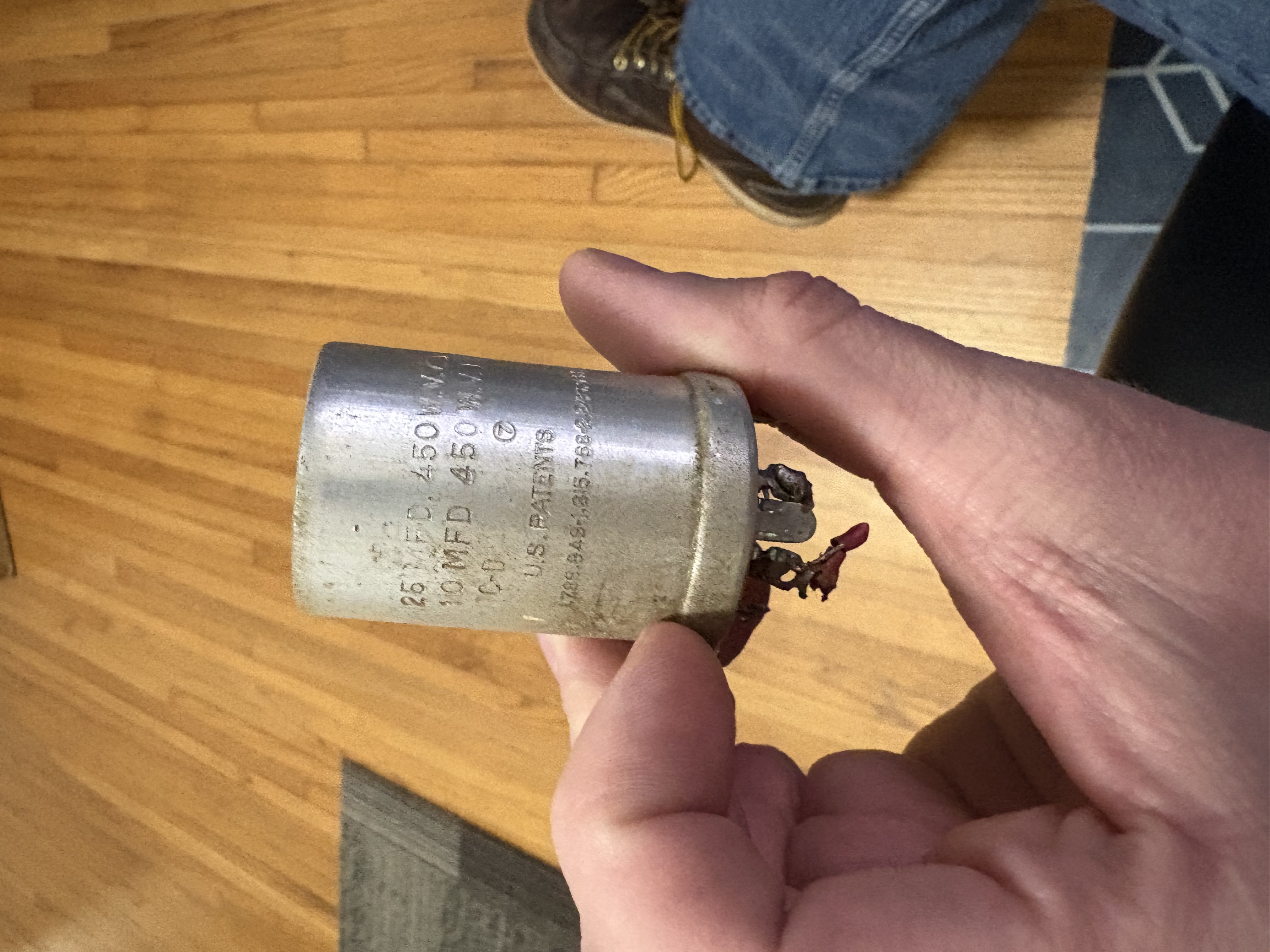
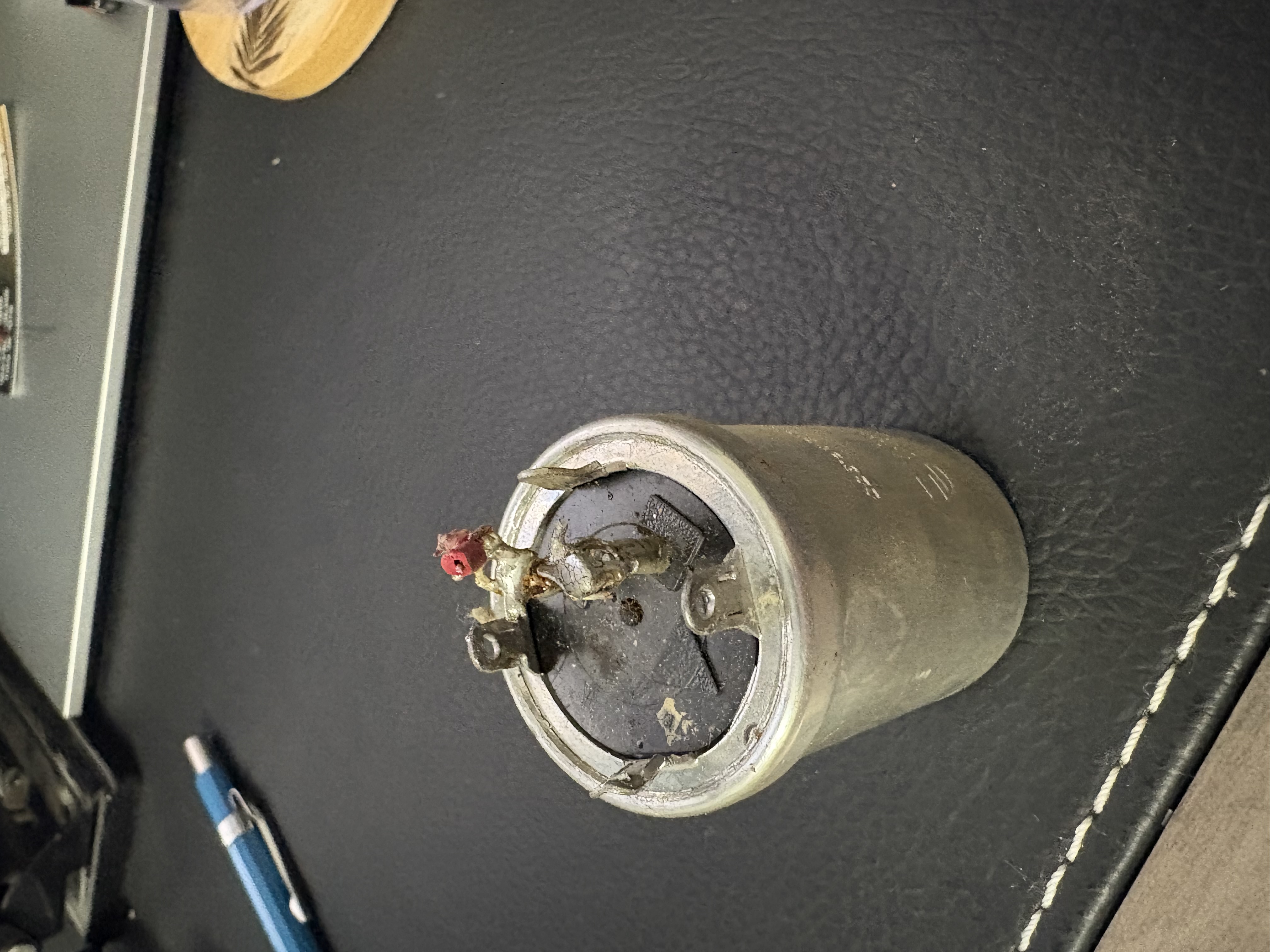


    I've gotten a lot of great feedback from folks here on the Phorum. I've been worried about the high voltage (340 V) being supplied by the 7F8 rectifier. I researched into dielectrics, clearance, and creepage. As it turns out, KiCAD has some tools. 
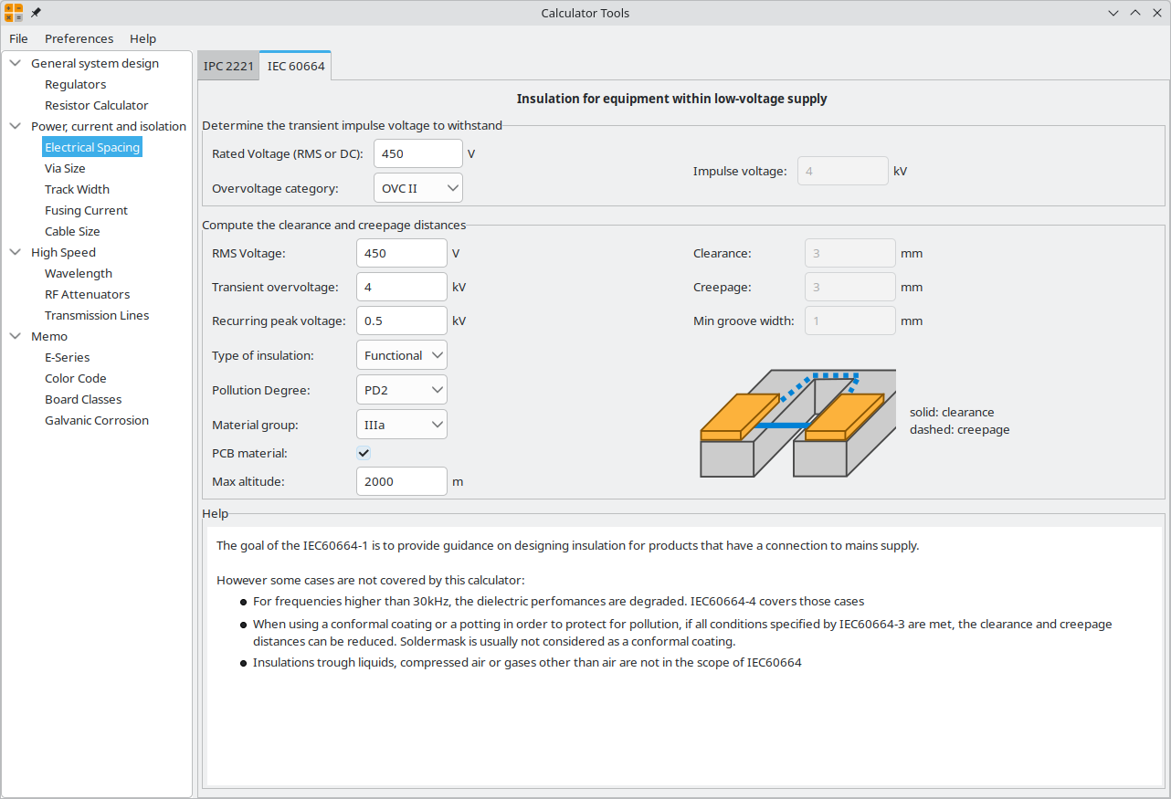
   

    There were two tools to use, one which follows the IPC 2221 guidelines and another which follows the more stringent IEC 60664 guidelines. I chose the latter. I made some conservative assumptions in order to design for worst-case scenarios. 
* Though there will only be 340 VDC, the Philco component is rated for 450 VDC. I figured I would match that, so I selected a working voltage of 450V. 
* I also read online that any consumer product which is plugged into AC mains via a disconnectable plug (i.e., anything which is not hardwired) must be designed to overvoltage category 2, meaning it must be able to withstand a transient voltage of four times the working voltage. This put me in the 4kV category for transient voltage.
* I selected functional insulation, as I am not installing any further insulation on this capactitor PCB to protect the end user. This will only feature the dielectric insulation, insulation from the connected wiring, etc.
* I selected pollution degree 2. I had to research this a bit. Some folks consider residential environments to be a pollution degree 1 environment while others consider it to be pollution degree 2. I opted for the worst case scenario of pollution degree 2. Essentially, environments with pollution degree 2 may encounter higher levels of dust and/or occasional exposure to moist air.
* I selected material group IIIa. I have always used OSH Park for my PCB manufacturing, so I browsed their website for information regarding the properties of their PCB cores (datasheet attached). The CTI of their core material is specified as >175. This is the minimum for material group IIIa.

    Given these assumptions, the tool determined that I need a minimum clearance of 3mm and a minimum creepage of 3mm. Simple enough! To determine the minimum trace width, I needed to know the current passing through these capacitors. I know that this is a 70 watt radio. Let's assume that the entire 70 watts passes through either one of those capacitors at 340 V. If P = V*I, then I = P/V = 70 watts / 340 V = 0.21A. Thus, the minimum trace width is just shy of 0.2mm. Mind you, the high-voltage winding of the transformer is rated to output 85mA, so this is a very conservative calculation. Even so, I had the real estate available on my PCB to make the traces a full 1.0mm wide. I had chosen a trace width of 1.0mm on the multi-section capacitor I designed for my 49-906 as well, and I've run that radio for at least 200 hours since. No issues whatsoever!.

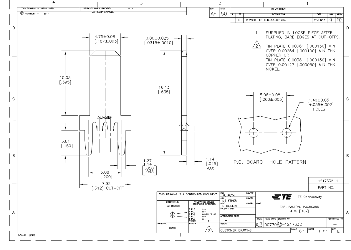
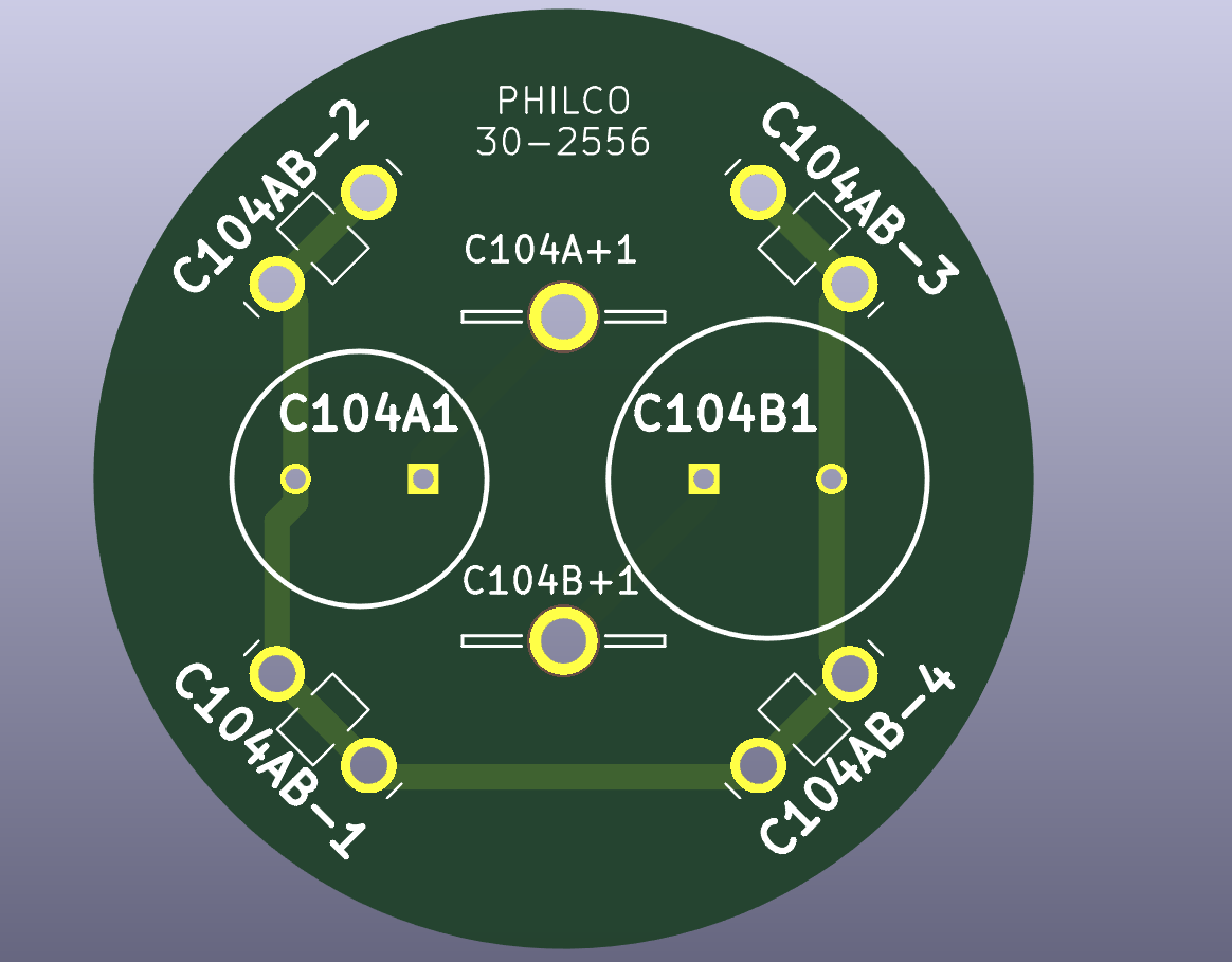
    Alright, so then it was time to design the PCB. I chose these QC connectors as a close replica of the twist lock connectors (thank you to Mike for recommending those to me). As he mentioned, I can cut a notch on either side to allow for a twist after sliding through the mounting cutouts in the chassis. I chose the 0.187" wide version. The mounting cutouts on the chassis measure 0.225" wide, and these were the largest size which would fit through without being too large. Remember that these connectors serve not only as the structural mounts to the chassis, but also as the negative connections to the two capacitors. There are four of these connectors, and they are all tied to the negative terminal of both capacitors. I could not find a current rating for this connector. I did, however, find a current rating for one of the smaller versions of this connector. It was rated for 2A. Thus, I believe that this larger connector will be plenty adequate. In any event, I am very confident that it will tolerate 85mA DC.
   

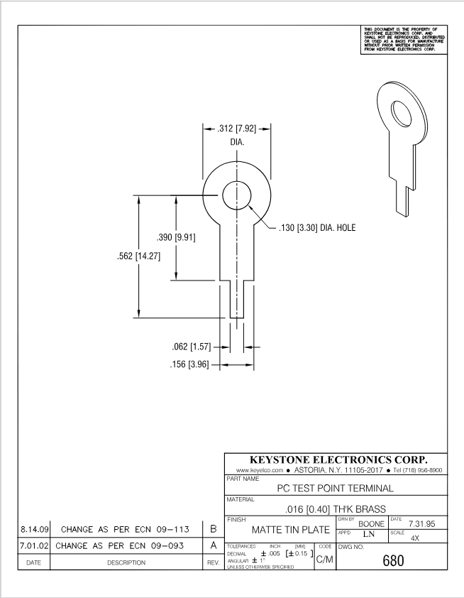
    I then selected these PCB-mounted solder lugs for the positive terminal of each capacitor. Note that the two capacitors' positive terminals are not electrically connected. I could not find a current rating for this connector at all, but given the comparable sizing of this solder lug to the QC connectors I believe it should be in the same ballpark. I am also confident that this connector will tolerate 85mA DC.
   

     Now to the capacitors. I ordered these back in late August after a discussion here on the Phorum. I have a Nichicon 10 µF, 450V, 20% electrolytic capacitor and a Nichicon 27 µF, 450V, 20% electrolytic capacitor (the original values were 10 µF and 25 µF, but I had to opt for a 27 µF replacement).

    PCB footprints were available on Mouser for all but the 27µF capacitor. I was able to copy and modify the footprint for the 10 µF model, though. Lead spacing was the same. All that differed was the diameter (10mm for the 27 µF capacitor vs 12.5mm for the 10 µF capacitor).

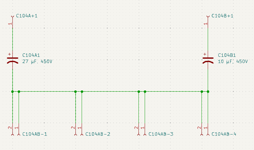
    Here's a look at the schematic. It looks funny for a schematic, but bear in mind that KiCAD thinks in terms of footprints. Each of the QC connector terminals has two through-hole connectors, hence the two-socket connectors. There are also a total of four of these terminals, and that's why there are four copies on the schematic.
   

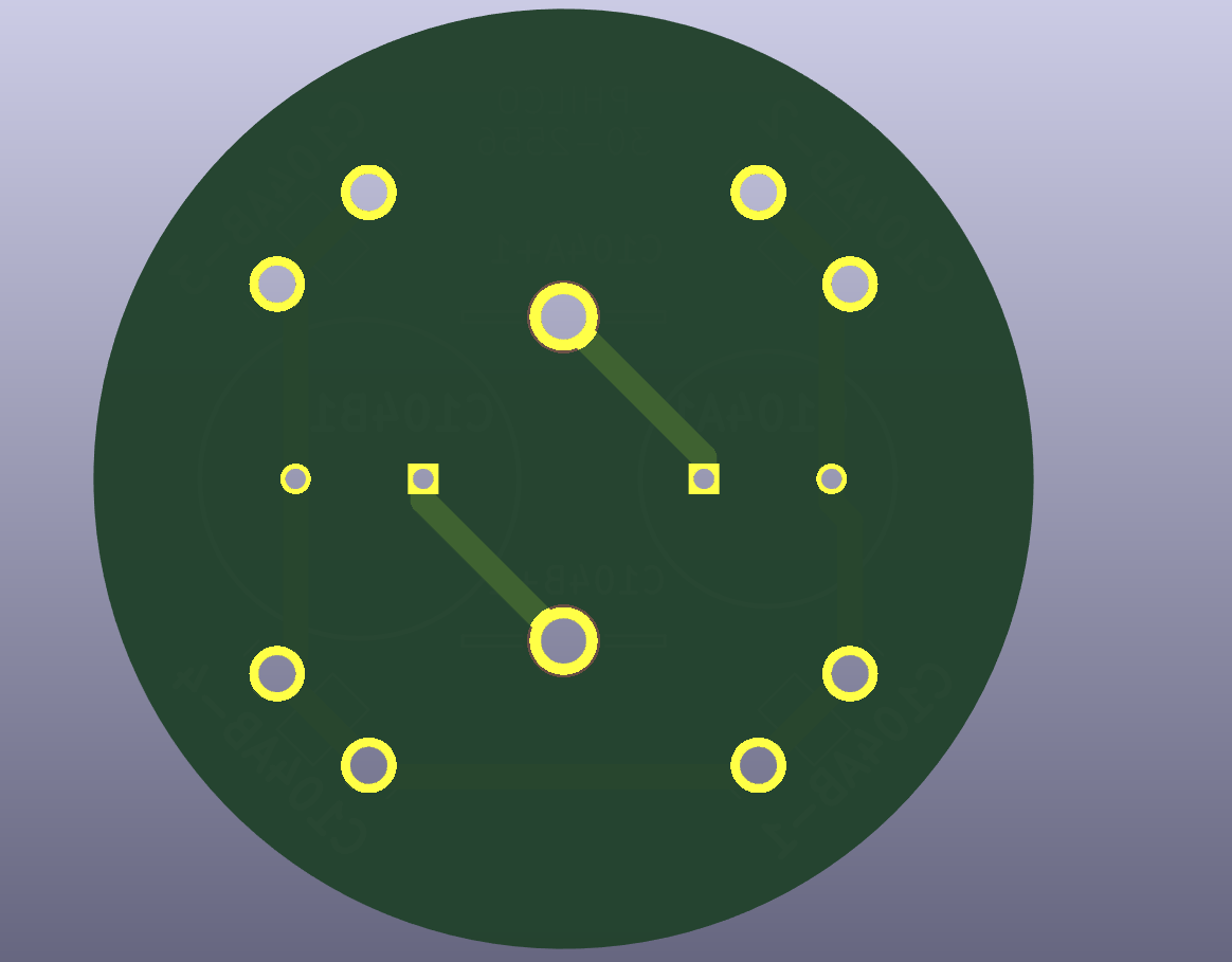
    From there I created the PCB. Here's a glance at the wireframe design.
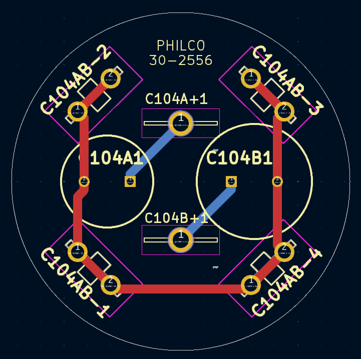
   

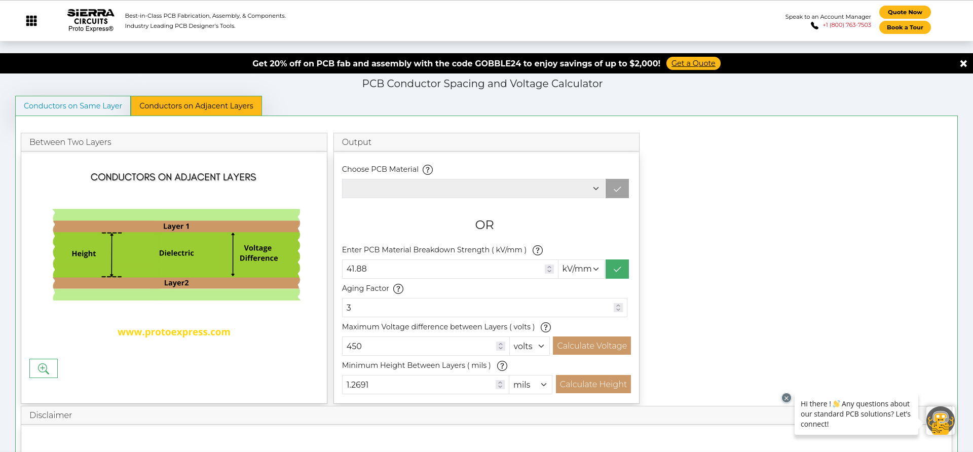
I placed all of the negative traces on the top copper trace layer (red), and the two positive traces on the bottom copper trace layer (blue). Note that there's no overlapping of these traces, but if there were then we would need to be mindful of the clearance between any two overlapping traces. According to one of the tools which OSH Park shared with me (https://designertools.app.protoexpress.com/?appid=CSCAL), the minimum separation of two traces rated for 450 V on adjacent layers would be 1.2691 mils. Here I have taken the dielectric breakdown of 67kV from the same attached datasheet. There's a note specifying that this value was calculated based upon test PCBs with an average thickness of 1.6mm, so I calculated a material breakdown strength of 41.88 kV/mm. 

    Per OSH Park's specifications, the core separating two layers of traces (speaking about their standard two-layer PCB) is 60 mils thick, +/- 6 mils. Thus, we are exceeding the minimum requirement of 1.2691mils of separation.
   

And here are the top and bottom views of the PCB from the 3D viewer tool.


Attached Files
.pdf two-layer-substrate-Kingboard-KB6167F.pdf Size: 226.89 KB  Downloads: 1

Joseph

Philco 46-480
Philco 49-906


Users browsing this thread: 4 Guest(s)
[-]
Recent Posts
$10 Fake Philco Baby Grand radio and a boring weekend
Who knew such a simple idea eould get so involved huh?Oldie Goldie — 05:31 AM
Philco 46-480 Electronic Restoration
Yep. It always help to put some sort of keepout outline, which is not necessarily the "keepout" keepout, bu...morzh — 11:58 PM
Philco 46-480 Electronic Restoration
Luckily my plan is for those solder lugs to be on the underside of the PCB, whereas the capacitors will be on the top si...jrblasde — 11:08 PM
Philco 46-480 Electronic Restoration
It always looks more colorful in CAD than on the PCB :lol: SInce I do not know the dimensions of your solder lugs/tabd,...morzh — 10:52 PM
Philco 46-480 Electronic Restoration
Here we are, I was able to relocate the solder lug connectors to be precisely 45 degrees from the respective terminal on...jrblasde — 10:49 PM
Philco 46-480 Electronic Restoration
BTA, the trick to add a teardrop to a pad that is not directly on the way of your 45 degree trace (your square pads) is ...morzh — 10:34 PM
Philco 46-480 Electronic Restoration
Here we are. Not too difficult at all! jrblasde — 10:17 PM
Philco 46-480 Electronic Restoration
Yes, fillet is another name for teardrops, or, rather, one of the type of it. The most popular one. Teardrops will not ...morzh — 10:12 PM
Philco 46-480 Electronic Restoration
Okay, yes. I’m familiar with the concept but knew it as a fillet. Let me make the modifications. You raise a good idea....jrblasde — 10:00 PM
Philco 46-480 Electronic Restoration
No. Teardrops is a style of a trace entry into a pad. morzh — 09:32 PM

[-]
Who's Online
There are currently 1693 online users. [Complete List]
» 1 Member(s) | 1692 Guest(s)
Avatar

>