Posts: 10
Threads: 3
Joined: Dec 2024
City: Denver
State, Province, Country: US-0-CO
Philco Phriends:
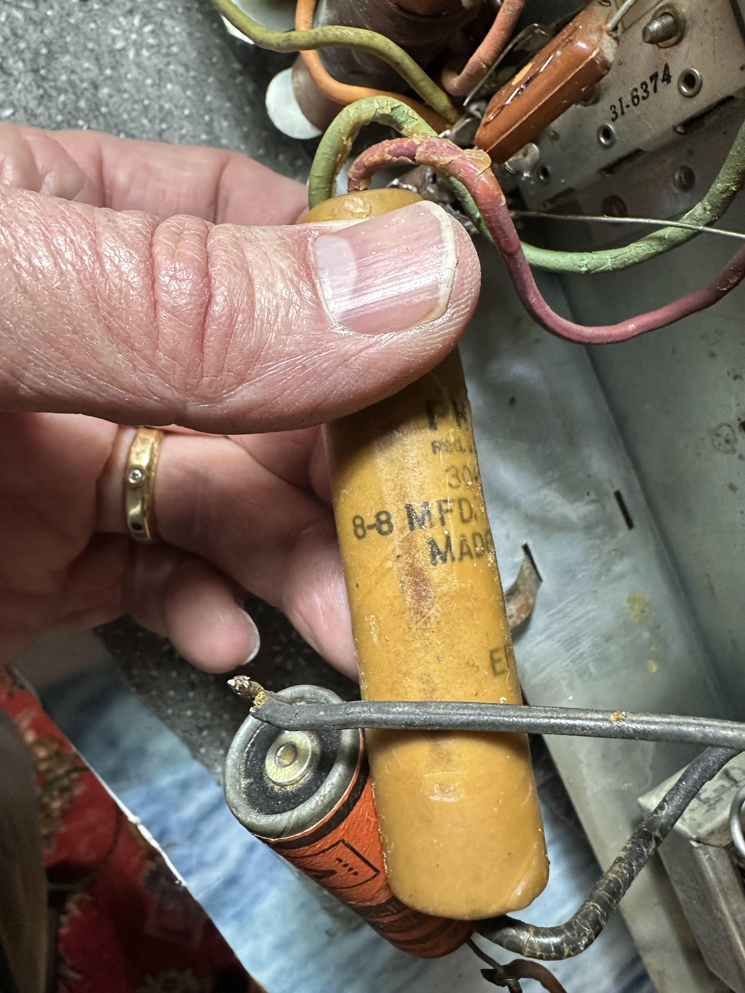
I'm working on my 42-365K, which I introduced to the Phorum last month.
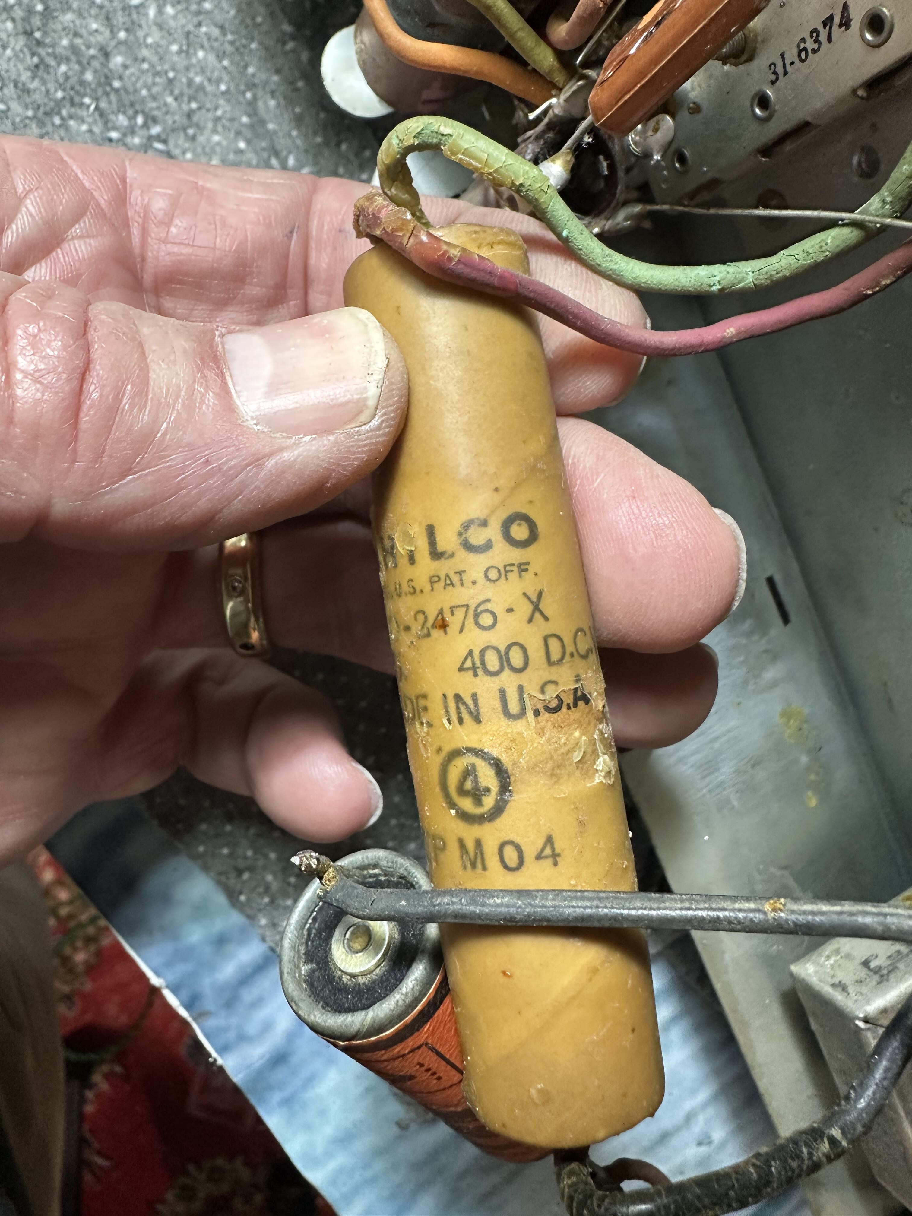
I have a plan to replace the biggest capacitors, which I believe get called electrolytics.
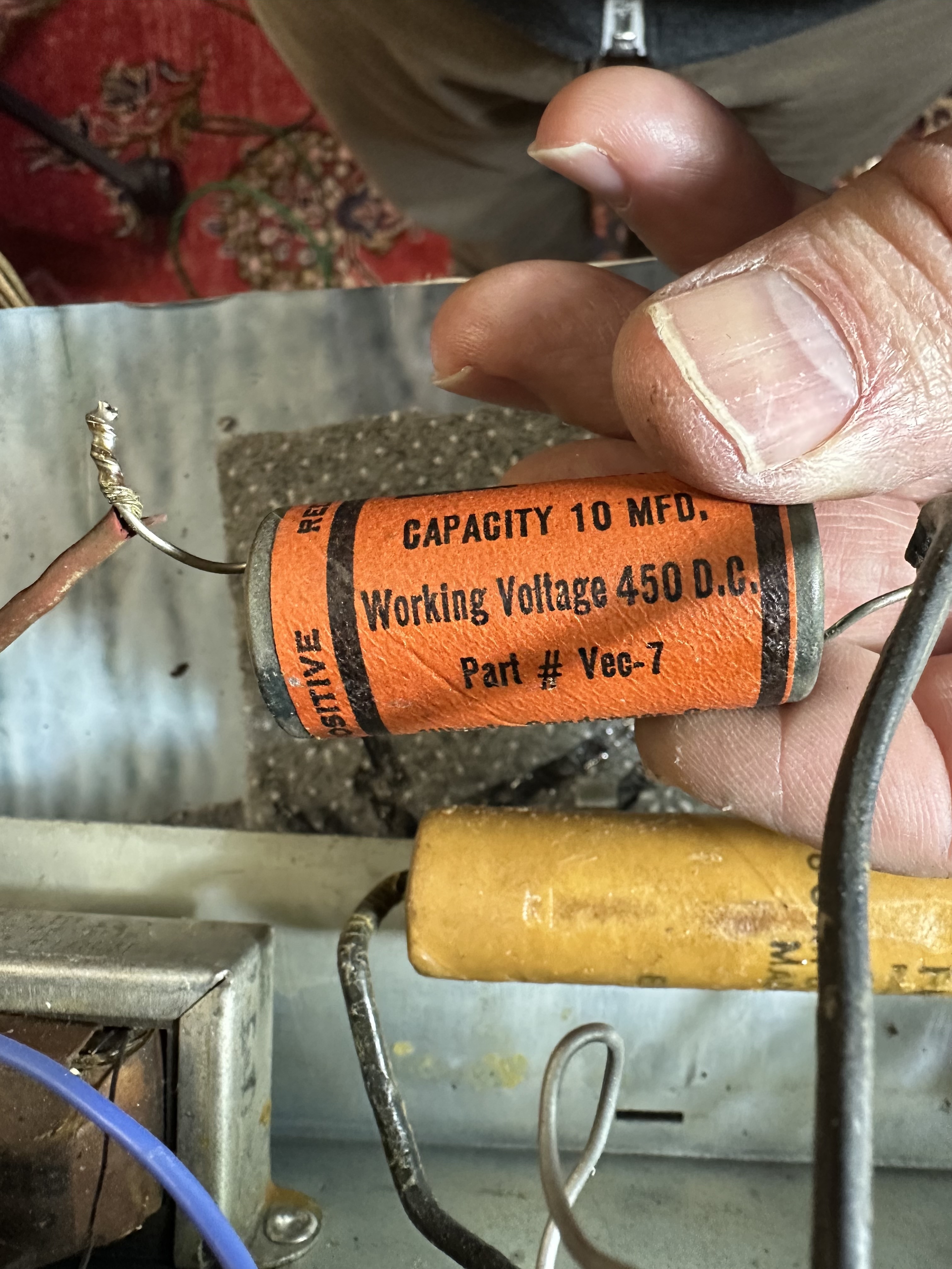
Here are some photos:

.

 I searched the archives and found Ron Ramirez's super helpful post from 16 years ago. He wrote:
"Okay. Here are the factory specs for the electrolytics used in Model 42-365:
"(37) Dual, 8 and 8 uF, 475 volts (per 1946 replacement 40-3003) - Part No. 30-2476
"(60) 12 uF, 400 volts - Part No. 30-2471
. . .
"Thus, armed with this information, it is safe to assume that 450 volt electrolytics will be just fine for this radio. In fact you could probably get by with 300 volt electrolytics for the two 8 uF units, but to simplify things, you may wish to go ahead and use 450 volts.
"8 and 12 uF are no longer standard values. 10 uF will be fine as substitutes for all three."
My questions are beginner basic.
Can I buy any 10 mfd 450 volt capacitors to replace the original monsters. For example, are these fine?
https://www.amazon.com/ALLECIN-Electroly...r=8-3&th=1
Second, how do I connect the 30-2476—which has two wires in and one wire out because, I think, there's a capacitor within the capacitor? Do I connect one new capacitor to the red wire, one to the green, and then both of them will connect to the black?
Note, btw, that I am replacing the rotten old rubber wires. (Side query: how was Philco getting rubber during WWII to use on the wiring of consumer radios?)
Once I replace these electrolytic capacitors and some of the worst wires, then I may turn to the other capacitors if the radio still works!
Thank you for helping a beginner. The question really is what replacement capacitors do I buy and how do I install the one that's a double.
Tom Russell
Posts: 243
Threads: 37
Joined: Jun 2022
City: Marion
State, Province, Country: NY
Hello Tom, If this was my radio I would be using 500 volt electrolytic caps. I would not be under sizing voltage ratings. I buy my capacitors and resistors from https://www.justradios.com/ Yes the dual cap would be wired as you say. The red and green wires are the positive side and the black wire is the negative side. I noticed the dual 8 does not indicate the positive or negative side but the 10 does. Based on what Ron said the 10 should be a 12, check your schematic. I think both of your caps are previous replacements.
Dan
(This post was last modified: 01-16-2025, 10:30 AM by dconant.)
Posts: 1,146
Threads: 47
Joined: Feb 2015
City: Roseville, MN
Hi Tom,
There's really no reason to use a higher voltage electrolytic capacitor than what the schematic shows unless it gives you a warm fuzzy feeling. Buying 500 volt electrolytic capacitors versus 450 will probably cost 50 per cent more. You'll also find that all the paper capacitors in your set will be in some stage of deterioration and will leak when DC voltage is applied or simply won't do the job when a signal is applied. You might as well order all the caps you'll need for the entire set as well as any resistors that are out of tolerance. It'll save shipping charges. I buy most of my parts from Mouser. Just Radios is also good. If you buy from either you can be sure of the quality. If I have an urgent need for one or two I'll find them on Amazon or ePay with free shipping.
Posts: 16,524
Threads: 573
Joined: Oct 2011
City: Jackson
State, Province, Country: NJ
Tom,
You are right to use 10uF 450V. 12uF is also fine, but for he very first cap after the rectifier you do not want to go much higher as this increases the voltage, and your tubes might run hotter.
300V Working voltage rating is not enough. 450V is good, and 500V is also popular.
For the second cap after the inductance (whether a choke or the Field coil of the speaker used as a filter choke) you could increase the capacitance if so desired, within reason; I often go with 22uF 450V/500V.
Now, this said, I would recommend NOT to buy caps from Amazon, with names like Allecin etc.
Also for that first capacitor, my recommendation is to go with those rated as "High ripple current" or "Lowe ESR" (which is almost the same).
The temp rating of 85C is OK, if it is 100uF, it is even better.
Panasonic is a very good source, sold in Mouser and other reputable places.
If you decide to go with film capacitors, this is fine too; if you decide to restuff the existing electrolytics with new caps inside them, the new electrolytics fit better inside due to smaller size. Many people do prefer the film caps, as they do not have limited life span, as the electrolytics do; however a well chosen electrolytic will outlive us all.
People who do not drink, do not smoke, do not eat red meat will one day feel really stupid lying there and dying from nothing.
Posts: 2,174
Threads: 158
Joined: Jan 2013
City: Westland, MI
Hello Tom. Having gotten the info you needed on capacitors, let's talk about the wiring in the pictures you provided. Some of the insulation is showing signs of hardening, splitting, and de-laminating. Inspect all wiring carefully. Insulation can be repaired by sleeving the wire with heat shrink tubing, or total replacement. If you chose the latter be sure to route new wiring in the chassis exactly as was originally. Take care and BE HEALTHY! Gary
"Don't pity the dead, pity the living, above all, those living without love."
Professor Albus Dumbledore
Gary - Westland Michigan
Posts: 1,262
Threads: 11
Joined: Jul 2020
City: Greenlawn
State, Province, Country: NY
Hi Pholks,
The 1942 model year for Philco actually started in 1941 when rubber wire was still available. (BTW, the rubber wire pictured in your radio is better than most. However, it should be replaced or covered with heat shrink tubing. The war started (for the US) on 12/07/1941, so it is likely that many of these sets were produced before the war started. Sometime in 1942, almost all civilian product production stopped because everyone from the Auto Industry (GM, Ford, Chrysler, Willys, Packard, etc.) Electronics Industry (RCA, GE, Westinghouse, Philco, Crosley, etc.) to rubber (Goodyear, etc.) to food, and so many other industries shifted to wartime production of products that they may never have produced, required for the War effort. For example, Crosley (and believe Philco) built proximity fuses. Ford built the B-24 "Liberator" Bombers, long after they stopped their dabbling in airplanes (The Stout Tri-Motor was bought by Ford in 1925 but Ford's interest ended in 1934) Chrysler built the Sherman tank as well as some of the trucks, GM built trucks and staff cars,
Willys and Ford built Jeeps, etc.
NCR (National Cash Register) played a very important part in building some of the earliest computers (almost fully electromechanical) used to crack many of the Japanese and German codes, which contributed greatly to the US winning WWII. Henry J. Kaiser, a construction Magnate (the Hoover and Grand Colee Dams), who never built a ship in his life, built the "Liberty" and "Victory" ships using mass production (welding, subassembly) construction.
"Do Justly, love Mercy and walk humbly with your God"- Micah 6:8
"Let us begin to do good"- St. Francis
Best Regards,
MrFixr55
Posts: 5,177
Threads: 276
Joined: Nov 2012
City: Wilsonville
State, Province, Country: OR
Here's a discussion of that rubber wiring that can be found in our Philco Library in the Shop Talk section:
https://philcoradio.com/library/index.ph...2-philcos/
Posts: 1,878
Threads: 120
Joined: May 2008
City: Omak
State, Province, Country: WA
Hello Tom,
few words of advice take lots of photos and mark the wires and don't do to much at one time so you don't get lost.
I have done half dozen sets that I had to rewire and I have sets waiting to work on too.
Ge, Philco and Zenith sets and some others all had the same issue .
Good luck !
Sincerely Richard
Users browsing this thread: 1 Guest(s)
|
|
Recent Posts
|
|
Philco 50-925 antenna connections
|
| Most loop antenna setups are either one continuous loop with two connections or 2 loops with 4 connections. The latter c...RodB — 02:16 PM |
|
Value of capacitor
|
| Not trying to answer for the OP, just commenting on the thread.
According to AI... ...assuming the electrolytic that'...HowardWoodard — 02:09 PM |
|
Philco 50-925 antenna connections
|
| Hello Keith! I've updated your thread with the proper model number. Take care, - GaryGarySP — 01:10 PM |
|
Value of capacitor
|
| Why are you having to replace it? Does it measure out of tolerance? Is it mechanically damaged?DaleHCook — 07:50 AM |
|
462ron
|
| Hi Keith, here is the official Philco service info found in the Philco Library under service info……https://philcoradio.c...462ron — 07:23 AM |
|
My collection presentation
|
| This article has been completely updated and finished.
The beginning of a portable collection.Vlad95 — 11:49 PM |
|
Philco 50-295 antenna connections
|
| Thanks Rod, That makes perfect sense. Is there a way to edit my post? It's a Philco 50-925 and not a Philco 50-295. D...keith49vj3 — 09:55 PM |
|
Philco 50-295 antenna connections
|
| C is for an external speaker.RodB — 08:39 PM |
|
Philco 370LZ chair side not a 71LZ
|
| Can you send a couple of pictures?slford310 — 07:11 PM |
|
Philco 370LZ chair side not a 71LZ
|
| Thank you for the reply. After much studying I figured it just sat there and you have to open the top and pull up and/o...Villager61 — 06:42 PM |
|
Who's Online
|
| There are currently no members online. |

|
 
|
 .
.


![[-] [-]](https://philcoradio.com/phorum/images/bootbb/collapse.png)


