HiFi (Chifi) tube amp build - but my own design.
Posts: 1,208
Threads: 85
Joined: Jan 2014
City: Annapolis, IL
State, Province, Country: USA
Ok, so I tried an experiment tonight. I put a switch on to kill the feedback or keep it in the circuit. Result? FAIL! That's a no-go. I thought it was great for a moment as the gain was tremendous and the highs and mids came alive, but so did the distortion, hum and all kinds of noise. Probably OK for a guitar amp, but on this HiFi amp, noooop. I also added a really cool Johnson Cinch jack to fill in an extra hole over the bias pot that I can use to check the bias voltage right on top of the chassis. So that experiment is a success. Once the current is set, you can check the voltage too. I have the voltage at -26.4 and current is about 30ma idle each tube. It's weird how the tone changes when you adjust this. This seems to be the sweet spot. It runs cool and had plenty of punch. It's really almost to the "leave it alone" point, and start on the next one. It's working really good right now. I almost hate to mess with it any more.
EDIT: The switch I added to turn on or off the NFB might actually not be a total failure. It could be used to help weed out marginal or noisy driver tubes. I note this in that some of the common 6GH8a's are noisy.
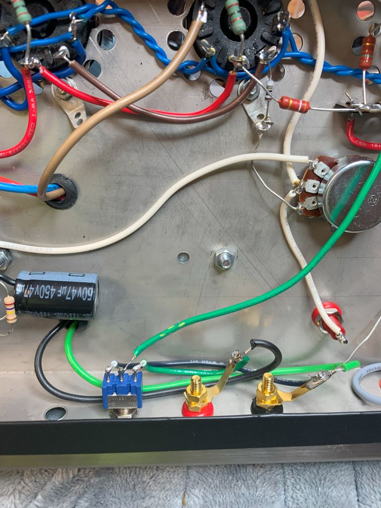
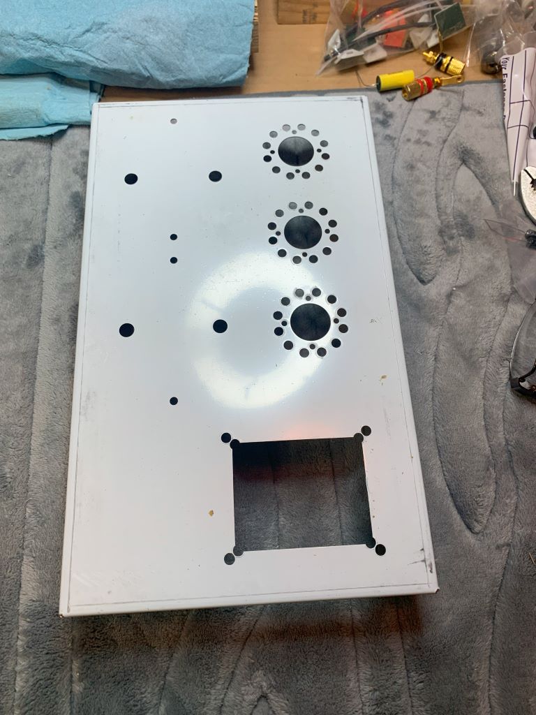
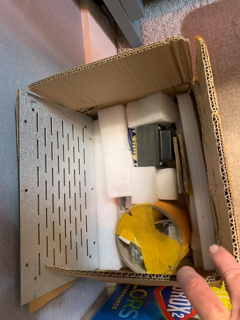
Sooo - at this point, time to start building it's twin sister. Now that I have the build down, I will try some more experiments as I go together with this one. Gonna try a better step bit and see if I can enlarge a couple tube holes for the octal sockets. I might attempt using a chassis punch, but not holding my breath that it'll work. If not, then I'll grab the die grinder and do a little more "redneck engineering" 
If I could find the place called "Somewhere", I could find "Anything" 
Tim
Jesus cried out and said, "Whoever believes in me , believes not in me but in him who sent me" John 12:44
(This post was last modified: 12-11-2024, 02:01 PM by TV MAN.)
Posts: 1,208
Threads: 85
Joined: Jan 2014
City: Annapolis, IL
State, Province, Country: USA
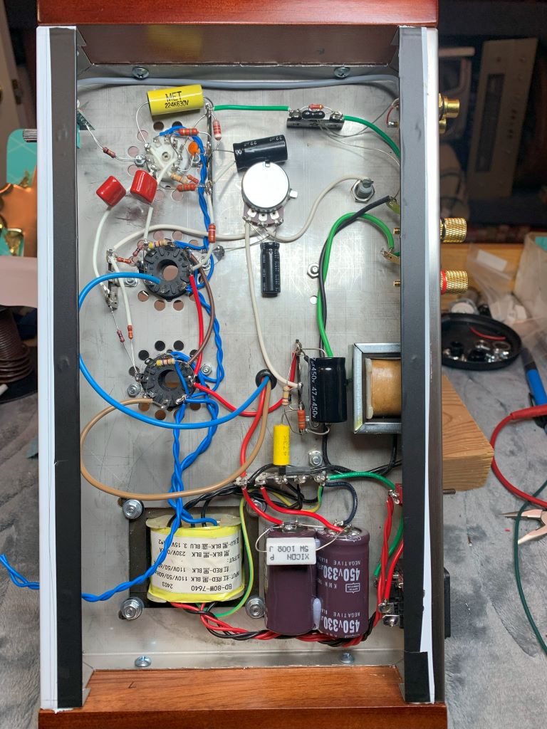
I finally had a chance to do a test power up on my twin amp build, which is a twin, but not identical twin. With this being my second crack at this, I revamped some things in the layout to simplify construction, clean up & be easier to service. I separated the FB network and put it on it's own terminal strip (upper RH corner) which cleaned up the terminal strip near the driver tube. I also rerouted some of the wiring around the driver to simplify. I pretty much left the output area as it was, except I am trying different screen resistors to see the effect on the G2. I used a 100r resistor on the original, tried a 4.7k and it only dropped it 10v. Just an experiment. I'll probably go back to 100 on the final, although I see a lot of those connected directly to B+. I personally feel there should be something there. I also moved the bias filter cap to the control. Plenty of room, and makes more sense to filter it there right before it's sent to the tubes, and neats up the bias terminal strip. I used different coupling caps, since I didn't order enough of the bigger ones. I'll see if it really makes a difference. They weren't cheap ones either, so I really don't expect anything super different. Same value.
You'll also note that I revamped the power supply. My initial was just that - an initial. I found that my choke fit the existing holes already in the rear of the chassis, and it fit perfectly in that area, which neats up the top of the chassis. I moved the filter caps between the PT and A/C plug, mounted to a couple stickys and glued in place, Stays put, yet not hard to snap off and replace when that day comes. I also used a 5w power resistor instead of that huge 10w. I let it play for 20 minutes and could lay my finger on it with out withdrawing forcefully. I'm using a plain ole 6GH8A driver, Japan, and a couple Russian made 6V6s.
It powered up beautifully without any setbacks other than the fact I must have put the line control in backwards. Simple fix. I did reverse the plate leads on the output tranny and had no feedback issues, so this DOES make a difference! It makes sense as this would reverse the phasing of the transformer. I found the blue lead (at least with this tranny) goes to the low side of the inverter, and the other (brown?) to the high side. I've made this mistake more than once on other amp builds, so learned something. I also had the SAME hum issues from the PT, so moved the trans nuts around and used washers and poly washers as before and made it totally quiet. Not quite as attractive as tying the transformer directly to the chassis, but I'll sacrifice some cosmos for performance. I'm still planning to play around with some other tube types and try a couple different output trannys but I need to set a standard for comparison. Next up is going to be a power, freq response and distortion test. So far my main tester (those 2 things on each side of my head) say is sounds pretty good!
Edit: Mike, I know you mentioned that large yellow cap by the driver tube. It has some pretty thick leads and feels solid. I ran the lead through the terminal strip to the socket. It's not going anywhere.
If I could find the place called "Somewhere", I could find "Anything" 
Tim
Jesus cried out and said, "Whoever believes in me , believes not in me but in him who sent me" John 12:44
(This post was last modified: 12-19-2024, 12:57 PM by TV MAN.)
Posts: 16,509
Threads: 572
Joined: Oct 2011
City: Jackson
State, Province, Country: NJ
Looks good.
Judging by the value of the caps, your rectifier is solid state?
If so, a small NTC to keep the inrush down could come handy.
People who do not drink, do not smoke, do not eat red meat will one day feel really stupid lying there and dying from nothing.
Posts: 1,208
Threads: 85
Joined: Jan 2014
City: Annapolis, IL
State, Province, Country: USA
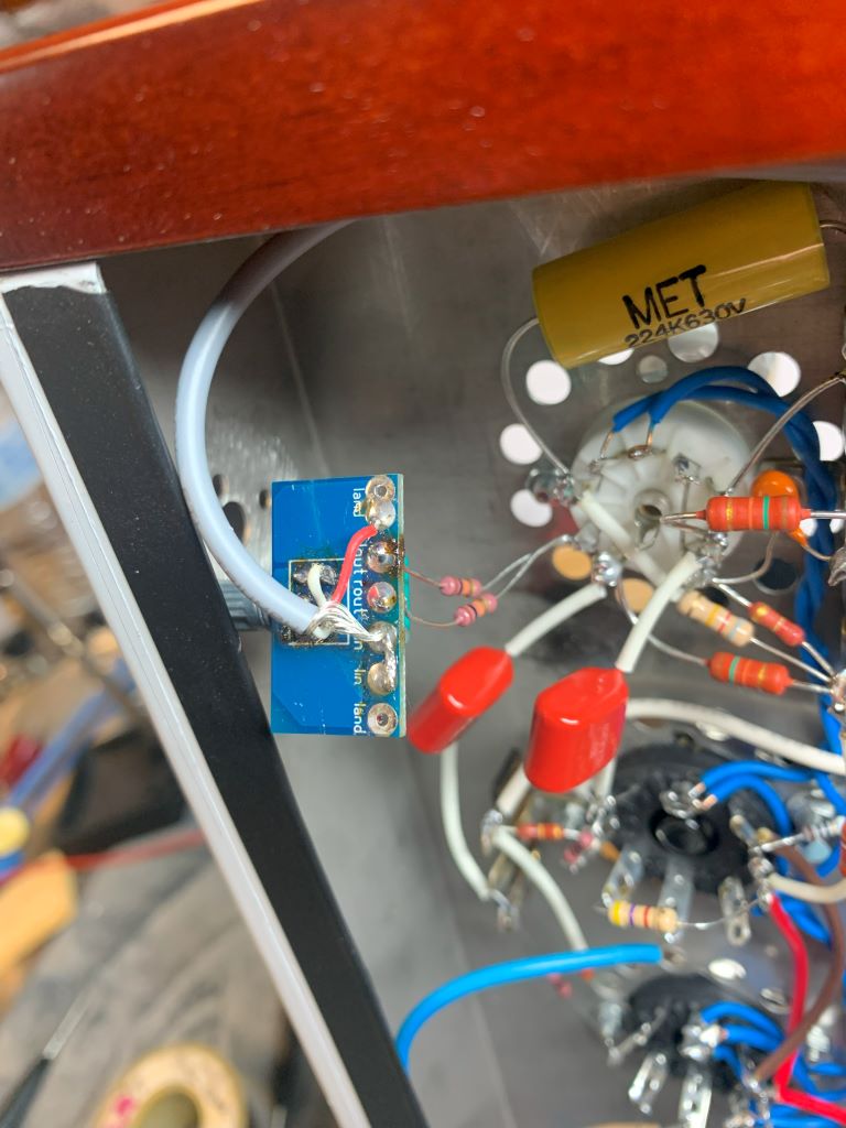
Mike, I have a CL90 I could put on. Honestly, I question if it really needs those big caps. Probably 47s would be fine. It's what came with the kit and they seem to work pretty good. I did reverse my level control. Ugh! Awful! You just TRY an desolder a 6 pin something without destroying it. I ended up cutting one of the traces and soldering direct to the control pins to make this thing work right. I have it set up so you can connect a stereo something or other and have it sound good. You can run it either way. Mono or stereo (mono).
Make SURE you solder that control on the side of that little PC board that has the square, otherwise - welcome to my world.
If I could find the place called "Somewhere", I could find "Anything" 
Tim
Jesus cried out and said, "Whoever believes in me , believes not in me but in him who sent me" John 12:44
Posts: 1,208
Threads: 85
Joined: Jan 2014
City: Annapolis, IL
State, Province, Country: USA
I did some testing, but I don't think my results are accurate. I think my scope is off, so I deleted until I can verify. I do know the amps sound pretty good, but I don't think I am getting the full output that I originally thought. So far, they sound really good on some 10" speakers I have, but they seem to lack a little on bigger speakers. That's about all I know at the moment.
If I could find the place called "Somewhere", I could find "Anything" 
Tim
Jesus cried out and said, "Whoever believes in me , believes not in me but in him who sent me" John 12:44
Posts: 1,208
Threads: 85
Joined: Jan 2014
City: Annapolis, IL
State, Province, Country: USA
I just finished some more power testing, and also used those testers on the sides of my head. Soooo - I tried several different sets of speakers and my PAT preamp. They both sounded about the same, pretty quiet and clean ... than is, until I really cranked it. Now bear in mind, even tho I'm an old timer (kinda), I like to feel my music as well as really hear it. That said, this should explain why I've blown a lot of foam speaker surrounds and tweeters. Sooo - back to the test. The 1st amp built sounded pretty OK up to clipping. That's where I backed off just a bit. The 2nd build, well, it lacked after just a shade over what I call 'cranked'. In fact, it sounded awful and fell totally flat!
Soooo - back on the bench! On my scope, I could only get about 21vPP before it clipped. I checked the other and it didn't clip until about 31v. I also tested my kit amp using the 6P1 version of the 6BQ5/6V6. and it peaked at about 33v before clipping. Woah! What?
So, then I remembered I'd left the 4.7K screen resistors on there, which is about the only difference I could think of. So I swapped for 100R. Powered back up and the output raised to about 28vPP before clipping. Then I jumped them, and that brought it up to about 29.5VPP before clipping. So, those screen resistors DO make a difference, even if idle voltages aren't much lower. A couple things that could also attribute to slightly different power output (very minimal) is that the tubes in the 2nd amp are very slightly lower emission, and a little farther apart concerning matching, where the 1st amp tubes are dead on matched. The other thing is for some reason my B+ is very slightly lower on the 2nd amp. The 1st is 330v on the 6V6 plates, and the 2nd is about 318 on the plates. The 1st kit is a little older, purchased in '22, and the 2nd is purchased within the last couple months. The Power trans might be slightly different. I'll do some more checking.
I also checked the signal at the grid of the inverter tube just to see how much and where it clips. Well, it is solid up to about the 90% setting, which is well below the setting where it clips on the output. I didn't check the output grids tho. Later.
I'm not sure how accurate my PP readings are on my scope, but I did note that the freq response was pretty flat from about -25hz to 15k (which is the highest I went), so as of right now, I'm not sure about the power output. I do know they sound good now.
If I could find the place called "Somewhere", I could find "Anything" 
Tim
Jesus cried out and said, "Whoever believes in me , believes not in me but in him who sent me" John 12:44
Posts: 16,509
Threads: 572
Joined: Oct 2011
City: Jackson
State, Province, Country: NJ
Tim
Those volts you measured: across the primary or across the load? If the latter...that is total too much.
If the primarey, OK, understood, though I do not know your turns ratio.
People who do not drink, do not smoke, do not eat red meat will one day feel really stupid lying there and dying from nothing.
Posts: 1,208
Threads: 85
Joined: Jan 2014
City: Annapolis, IL
State, Province, Country: USA
I finally have some numbers. It took watching a few YouTube videos and measurements to get there, but the tally is in. My scope IS accurate, which I confirmed with my Fluke. With my 1st tests on the 2nd amp, nothing was adding up or making sense. Now I know why. Never would have imagined the G2 resistors would have made that much difference, but they did! So, I corrected that and did some more tests and this time things made sense. My scope showed right around 30VPP, which I divided in half, then X .707, which gave me about 10.6v, then squared and divided by 8. and that gave my right at 14w. I confirmed the RMS voltage with my Fluke at 10.65 and used the same formula. This makes sense since I built the amp to push about 15w. So, it's doing close to what it should. With the 4.7k screen resistors, it was only pushing about 8w! So, no wonder it sounded so lousy when I pushed it. It sounds much better now. The 1st unit pushes 31v, which puts at at 15w. It's kinda hard to get an exact reading because the level control is stepped, but I can also adj the signal generator too. But, it's close, and about what a pair of 6V6s are suppose to put out.
A note: The PP kit amp put's out about 17w (33vPP). It DOES sound just a little stronger when I push it. It's actually rated at 12w, but I think since our line voltage is higher than 110 that it raises the B+. It could also be under rated.
My scope is just a little hand held unit and it's kinda hard to see things very clear, but I can see when the signal starts clipping. . I've got my eye on a new one with a bigger screen that I may pull the trigger on. This is still an experiment. More to come.
Edit: Mike, they are on the primary of the OP tranny. I think the lower B+ on the 2nd amp build is cutting my wattage slightly. The output across the load is in the 10.6-11v range A/C or 30-31v PP
If I could find the place called "Somewhere", I could find "Anything" 
Tim
Jesus cried out and said, "Whoever believes in me , believes not in me but in him who sent me" John 12:44
(This post was last modified: 12-21-2024, 02:57 PM by TV MAN.)
Posts: 1,208
Threads: 85
Joined: Jan 2014
City: Annapolis, IL
State, Province, Country: USA
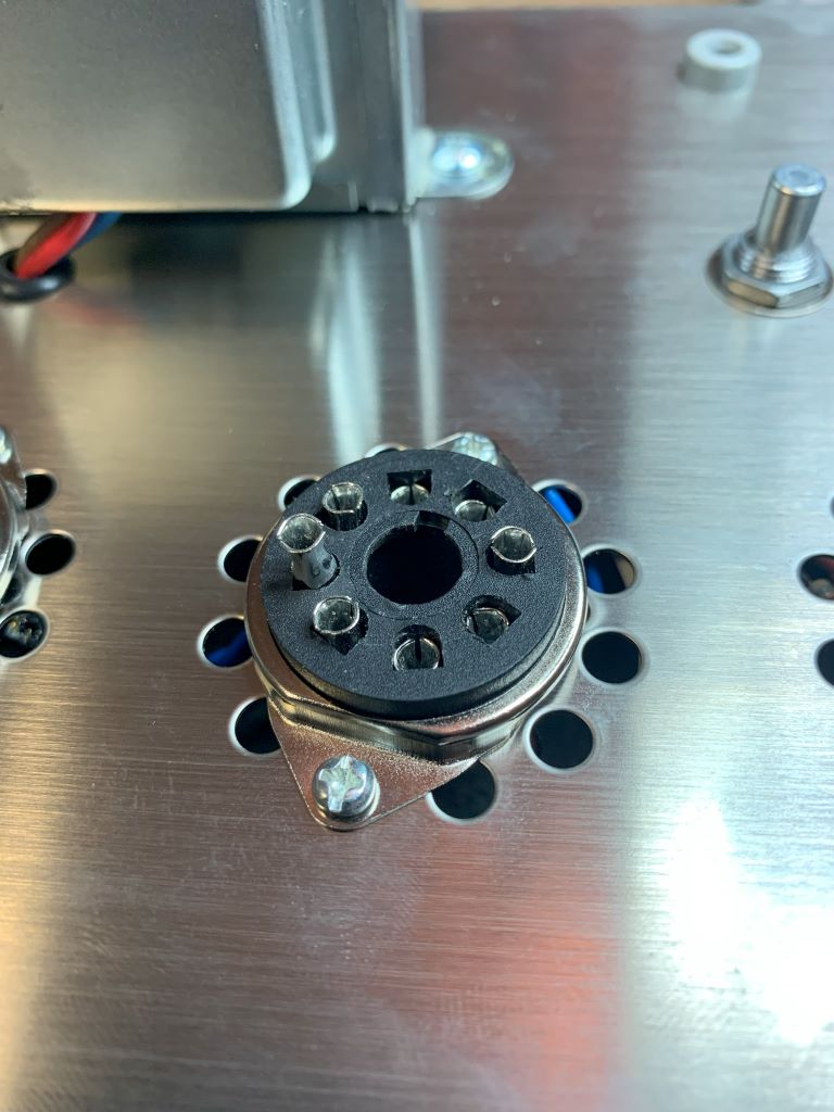
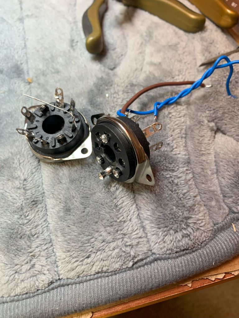
Hey all! I've been pretty quiet on this one because I'd been having some "mystery" problems, which really left me scratching my head. Amp 2 would work great, then it wouldn't, then it would, then it wouldn't. I've been testing different tube types, taking measurements, trying different voltages, having problems with red plating on different tubes, oscillations, then even having problems with sometimes one of the tubes not lighting up! I finally found the cuplrit(s). The octal tube sockets are junk! Usually if a socket is bad, you can move the tube around and get it to work or not work. Not in this case. I did have an occasional static in amp 1 and could move one of the tubes (same sockets) and get it to kinda quit. Figured it was a cold solder or something. It really came to a head when I stuck a "nice" set of 6V6's in there, and couldn't get things to sound right. Bass was weird, mids were scratchy - then they weren't, oscillations, low power ... things I wrote off as bad/weak tubes! Then I noted that only 1 6V6 was that nice pretty blue when I turned off the lights ... voltages checked fine. Well - ya get the point! This was a tough one! And now, almost all my tests and tweaks - trash can! I suspect it was losing G2 voltage. How would you even test for something like this? Maybe a socket adapter? Even pulling the tube partially out might affect things. So anyways, learn from my mistake.
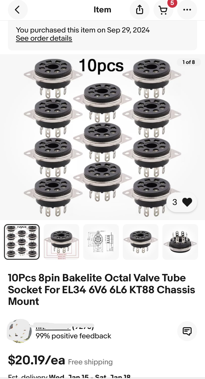
AVOID these sockets! Save yourself some misery. These came from the auction site. I'm not bashing any particular seller either, but these "bakelite" sockets are JUNK! I suggest some ceramic sockets.
If I could find the place called "Somewhere", I could find "Anything" 
Tim
Jesus cried out and said, "Whoever believes in me , believes not in me but in him who sent me" John 12:44
(This post was last modified: 01-13-2025, 12:34 PM by TV MAN.)
Posts: 1,254
Threads: 11
Joined: Jul 2020
City: Greenlawn
State, Province, Country: NY
Did the "bakelite" melt during soldering? Bad enough that the pins pull out, but the real issue is pin tension and not losing the springiness and tension of the pins. Hopefully the ceramic sockets don't use the same pins. I am not immediately running out to build a kit amp as I have 2 Fisher Tube receivers, (400 and 800B) a Scott 299 (if I can pry that back from my brother) a Dunhill (Harman Kardon) integrated amp, a bunch of Heathkits in various states of disrepair, but having 2 Acrosound TO300 transformers, 2 Bogen Challenger 100s,A Dynaco Mark IV, 2 Scott Mono amps (one an integrated amp, the other only a monoblock, with no pairs for either, etc., etc., etc.
Eventually, I have to post some of this on eBay (Have bought much but not these items, but never sold anything on eBay), then consider building some monoblocks or stereo amps, maybe 2 out of the Acrosounds, with 5881s or 6L6s or 2 out of the Bogen Challengers (a monster stereo amp with 4 7591s per channel. Problem is that 7591s are expensive as all heck!
BTW, High power amps are not always about power, they are about transients. One of the hardest types of music to reproduce is classical music. Pop music throughout the ages may have, in fact, been tailored for the recording and reproduction state of the art at the time. most Classical and Sacred music was written before either mechanical or electronic recording and reproduction. It has been said that it takes 200W just to reproduce the sound of a grand piano, especially the attack and decay, with accuracy.
"Do Justly, love Mercy and walk humbly with your God"- Micah 6:8
"Let us begin to do good"- St. Francis
Best Regards,
MrFixr55
Posts: 1,208
Threads: 85
Joined: Jan 2014
City: Annapolis, IL
State, Province, Country: USA
I got some NOS sockets from a vendor in the US, but got buried working on my Emerson. I have seen the pins pull out of the ceramics too, but don't recall any connection problems. I guess they don't always get that little clip bent right that holds the pin in. But, I've had problems with those sockets in both amps. Got them from a US vendor. I'm going to order some better ceramic sockets from over seas and give them a try. I've gotten some others that seem OK. Just have to watch not to crack them.
I have a couple Fisher 500c receivers and started to restore one, but got mad with so many different opinions at the time. I'd like to finish those and discern the advices and see what works best. I bought a bunch of 7591a tubes before the prices went stupid, so I don't lack. I'm really wanting to get of my couple Dyna Mk3s running again. (shelf time) and my Pas 2 recapped. I'm still interested in building a few more amps of my own design. Bucket list ya know. Might give me a holler when you're ready to turn loose of some of that stuff. I have a few of my own that I may shove on eBay myself.
If I could find the place called "Somewhere", I could find "Anything" 
Tim
Jesus cried out and said, "Whoever believes in me , believes not in me but in him who sent me" John 12:44
Posts: 4,899
Threads: 54
Joined: Sep 2008
City: Sandwick, BC, CA
Tim;
I'm not even sure that those sockets were molded out of Bakelite, the texture makes them look like they are molded out of some other form of plastic, and the bracket makes them look sort of like a Cinch made sockets, except the Cinch ones are old bottom mount ones. The last time I bought new tube sockets I had two choices other then paying ripoff prices for so called NOS North American made ones, buy Chinese ones, or buy Soviet/Russian ones, so I bought some from a guy in Ukraine. The ones I got look like a Soviet interpretation of top mounted Amphenol octal Sockets, but I like how they reworked the terminals, they made them thicker, and made a slot instead of a pair of holes. One thing is all have the dimensions given in metric, so to make the Soviet Amphenol copies work I had to turn them down in a lathe about .020'' of an inch to fit the chassis holes.
Other then this I typically used second hand sockets salvaged from a scrap chassis, either by me or someone else. I have heard mixed opinions about the porcelain sockets (China sockets from China) not to do with lose contacts but apparently the terminals can snap off, but that may be due to rough handling, and they may vary between manufacturers.
Regards
Arran
Posts: 1,868
Threads: 120
Joined: May 2008
City: Omak
State, Province, Country: WA
Hello Arran,
I too bought some of those tube sockets from a guy in Ukraine.
I have not used them yet but they sure look well made ,
they are for a amp project.
Sincerely Richard
Posts: 1,208
Threads: 85
Joined: Jan 2014
City: Annapolis, IL
State, Province, Country: USA
I got some sockets that were supposidly NOS, but when they showed up, they were in a bag marked "China". They didn't fit any of the screw holes and were smaller. Should have returned them but by the time I paid the shipping and took the time, wasn't worth it. So for the moment, I put a couple extra sockets I had left over, will, you can imagine this didn't help. Same problems. So, ordering some ceramic ones from over seas. I have some but they are bottom mount and don't look very good. Amp 2 still sounds a little lackluster, could be the socket. Just not sure yet. Arran, I'm not sure what they are made from. I didn't notice any melting, but I might try the soldering iron trick on one I know is junk. Now, I'm curious.
If I could find the place called "Somewhere", I could find "Anything" 
Tim
Jesus cried out and said, "Whoever believes in me , believes not in me but in him who sent me" John 12:44
(This post was last modified: 03-17-2025, 11:20 AM by TV MAN.)
Posts: 4,899
Threads: 54
Joined: Sep 2008
City: Sandwick, BC, CA
Tim;
I noticed your post a little late, but I would take one of the junk sockets and try to break a chunk out of it with a hammer, or with a screwdriver blade. We all know how Bakelite breaks, with that rough texture, would they make a socket out of Teflon, I would guess not since phenolic resin is cheaper? If you can find some Soviet/Russian sockets, those would be good, I also remember seeing some from a Bulgarian seller of a different style where the ears were molded in, I have some similar ones to those made by Eby, but most of the Iron curtain stuff was either a copy of, or a derivative of something Western anyhow. Some other sockets that I was looking at once were some relay ones made by Omron, I think it was a seller in Taiwan, or Thailand wo was selling those.
Regards
Arran
(This post was last modified: 04-03-2025, 09:15 PM by Arran.)
Users browsing this thread: 2 Guest(s)
|
|
Recent Posts
|
|
philco predicta
|
| Hi CGL18,
First off, welcome to the Philco Phorum. I have not worked on a TV for a while but here are some givens:
...MrFixr55 — 08:22 AM |
|
Another amp build - here I go again!
|
| Sweet!
I actually have a Dynaco Mark 4 that I had been running with 6L6s with no mods. Seemed to my 14-year-old head a...MrFixr55 — 12:57 AM |
|
PT-6 finished!!
|
| Hi Gang,
Tube heaters are not "Ohmic" devices (that maintain specified resistance over wide temperature, c...MrFixr55 — 12:03 AM |
|
Electrolytic restuffing/internals
|
| Look here:
Philco-F676-124
Vlad95 — 08:02 PM |
|
PT-6 finished!!
|
| Well the 35Z3 doesn't have a tap on the tube heater for a pilot light, so in this set they have the dial lamp paralleled...Arran — 06:21 PM |
|
Electrolytic restuffing/internals
|
| Thanks. I think I try to cut this as suggested. I don’t have a lathe, but I do have a tap and die set. I am going to see...bridkarl — 04:46 PM |
|
Another amp build - here I go again!
|
| Hey all! Well, I guess that with what I learned from my last build, it's time to move up the ladder another rung and tak...TV MAN — 04:38 PM |
|
Electrolytic restuffing/internals
|
| There are various ways to handle this, one is to cut near just above that rolled in area is near the bottom, using the r...Arran — 04:36 PM |
|
philco predicta
|
| If you have a television signal generator (a must-have for TV repair) and an oscilloscope (the same), then this problem ...RadioSvit — 04:23 PM |
|
HiFi (Chifi) tube amp build - but my own design.
|
| Thanks Rod for the offer but I don't think those would work. There's some differences in the sizing and mounting holes b...TV MAN — 03:13 PM |
|
Who's Online
|
There are currently 275 online users. [Complete List]
» 3 Member(s) | 272 Guest(s)
|
|
|

|
 
|


![[-] [-]](https://philcoradio.com/phorum/images/bootbb/collapse.png)


