Atwater-Kent 84, restoration.
Posts: 16,524
Threads: 573
Joined: Oct 2011
City: Jackson
State, Province, Country: NJ
Well, in the declining years folks sometimes tend to use what disposable income they have left to pamper themselves to their youth's dreams which they had no money when they were young and no time when they were mature.
After all money is not to be taken to the grave, so why not treat oneself to one or two luxuries that we salivated all over in our teens...
People who do not drink, do not smoke, do not eat red meat will one day feel really stupid lying there and dying from nothing.
Posts: 16,524
Threads: 573
Joined: Oct 2011
City: Jackson
State, Province, Country: NJ
My memory had not failed me when I was writing about those inductances. I found them, both 5.6mH and 10mH, both small axial ones.
So, I think, I will use the 10mH one; it is about 47 Ohm (which I think is not even important) and about 40mA (which is way more than I need there).
Today I could not do anything: came home, cook the meal, took out the recycling (ours is every other week, so it is lots of it), called mom...by then it was already 8pm.
Not today, no...
People who do not drink, do not smoke, do not eat red meat will one day feel really stupid lying there and dying from nothing.
Posts: 16,524
Threads: 573
Joined: Oct 2011
City: Jackson
State, Province, Country: NJ
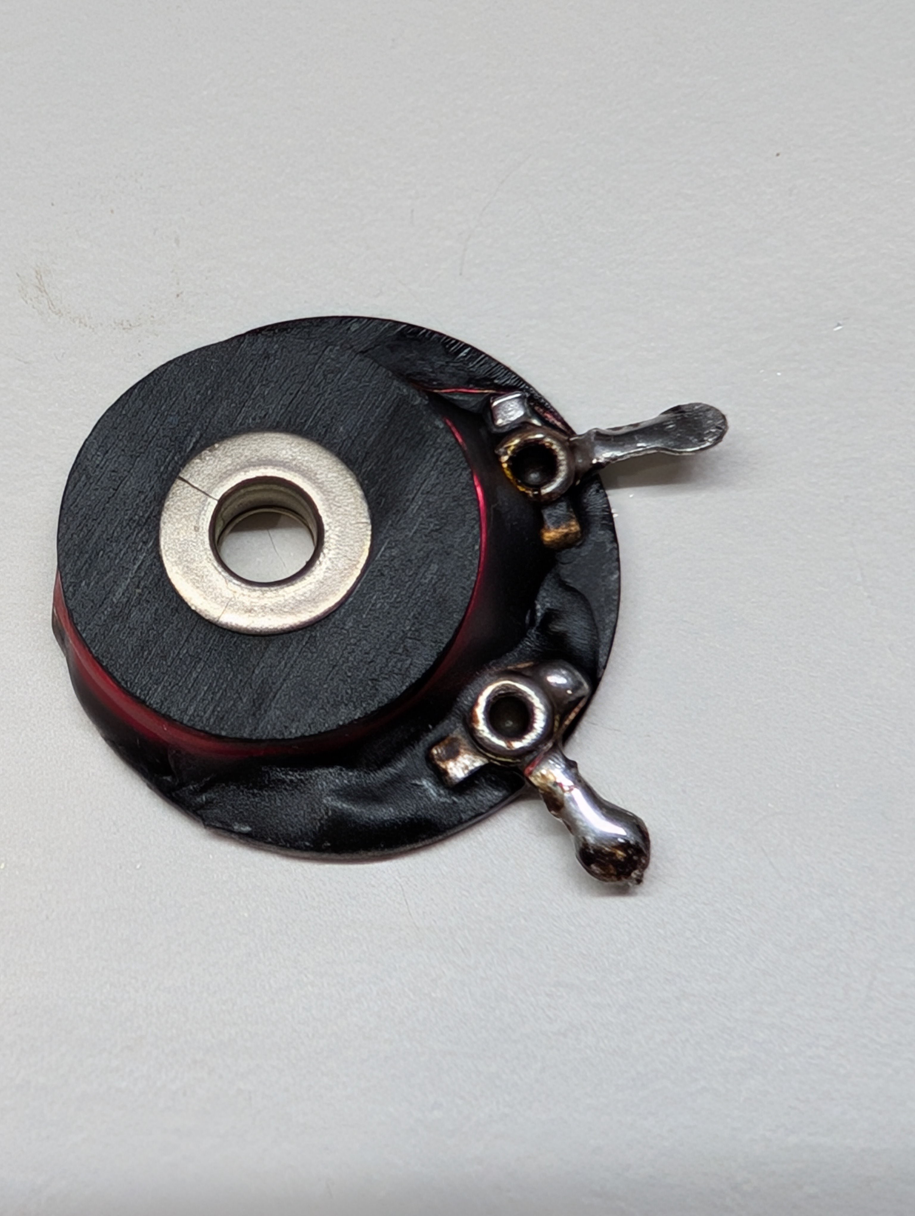
So, I sat down, and first tried 40 AWG wire. It broke quickly. I retook diameter: this one was 0.05mm whereas the one I took off was 0.08 to 0.09mm.
I took AWG 38 I have, which is 0.09 to 0.1mm, and in 30 minutes or so put manually 580 turns (it was 700). Condisdering this is a filter choke, this should be just fine.
I took the ohhmeter to it, and it gave me 64-65 Ohm (66 is the target), so that was right on, and the inductance on my LCR was 5.2mH (my first calculated value on one of the inductance calculator was 6mH).
So it is just fine.
I took a candle and heatgun and potted the open wire.
Tomorrow I will connect it back and try to power up.
People who do not drink, do not smoke, do not eat red meat will one day feel really stupid lying there and dying from nothing.
Posts: 1,877
Threads: 120
Joined: May 2008
City: Omak
State, Province, Country: WA
Hello mike,
Nice job hopefully it works and I am sure it will.
Sincerely Richard
Posts: 4,904
Threads: 54
Joined: Sep 2008
City: Sandwick, BC, CA
Mike;
Where was this RF choke located? I remember seeing on a few sets that had detector-amplifiers ahead of the power output stage that that they often had an RF choke involved to prevent IF interference from getting into the audio (at least it think that was what it was for). Sets that had a proper second detector diode, or pair of diodes didn't need it so much.
Regards
Arran
Posts: 16,524
Threads: 573
Joined: Oct 2011
City: Jackson
State, Province, Country: NJ
http://www.nostalgiaair.org/PagesByModel...001491.pdf
The 66 Ohm filter in the 1st detector's plate circuit.
Look in the early version sch.
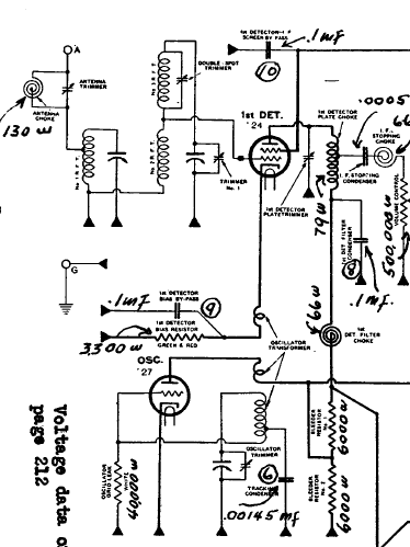
Here it is, the spiral that marked 66 Ohms.
I should've just used that 5.6mH or 10mH small inductance I have, but then I just wanted that a bit more original...absolutely no reason for it.
People who do not drink, do not smoke, do not eat red meat will one day feel really stupid lying there and dying from nothing.
Posts: 16,524
Threads: 573
Joined: Oct 2011
City: Jackson
State, Province, Country: NJ
Almost decided ot turn it on, but didn't like the power switch being 50 - 100 Ohms, so it is the same exact switch as in 96, and I gave it the same exact treatment: sprayed D5 into the small opening under the domed lid from both sides and worked it a bit.
Tomorrow then.
People who do not drink, do not smoke, do not eat red meat will one day feel really stupid lying there and dying from nothing.
Posts: 1,877
Threads: 120
Joined: May 2008
City: Omak
State, Province, Country: WA
Hello Mike,
that D5 is great for switches and I do the same I will try spraying it through a side hole first before taking it apart .
Sincerely Richard
Posts: 16,524
Threads: 573
Joined: Oct 2011
City: Jackson
State, Province, Country: NJ
That one cannot be taken apart well. It is riveted. But the domed switch luckily has some spacing (not much and not intentional), and oen could even see the actuator move through it.
This is what I use.
People who do not drink, do not smoke, do not eat red meat will one day feel really stupid lying there and dying from nothing.
Posts: 1,877
Threads: 120
Joined: May 2008
City: Omak
State, Province, Country: WA
Hello mike,
that is lucky that you were able to do that !
I have one of my radios that the volume control is getting scratchy again hopefully it's does not have bad spot .
Sincerely Richard
Posts: 878
Threads: 51
Joined: Feb 2013
City: Shenandoah,
State, Province, Country: Pennsylvania
Interesting design in that the plate circuits of the first detector and IF stage take full B+ right from the filament of the 80 rectifier with only small resistances in series of coils and IF transformer. The negative end of the power supply from the center tap of the power transformer going through a series of resistors and the field coil instead of putting the fc in the B+ side, my Philco 37-116 has a similar design!
Ron
Bendix 0626. RCA T64 Philco 20B
Philco 41-250. Philco49-500
GE 201. Philco 39-25
Motorola 61X13. Philco 46-42 Crosley 52TQ
Philco 37-116. Philco 70
AK 35 Philco 46-350
Philco 620B. Zenith Transoceanic B-600
Philco 60B. Majestic 50
Philco 52-944. AK 84
Posts: 16,524
Threads: 573
Joined: Oct 2011
City: Jackson
State, Province, Country: NJ
So...
4 out of 5 resistors in the resistor section were too much off, so I had to fix it.
I opened up the caps, removed the rod, and then parallelled the proper value resistor to them. Pretty much using them as solder posts.
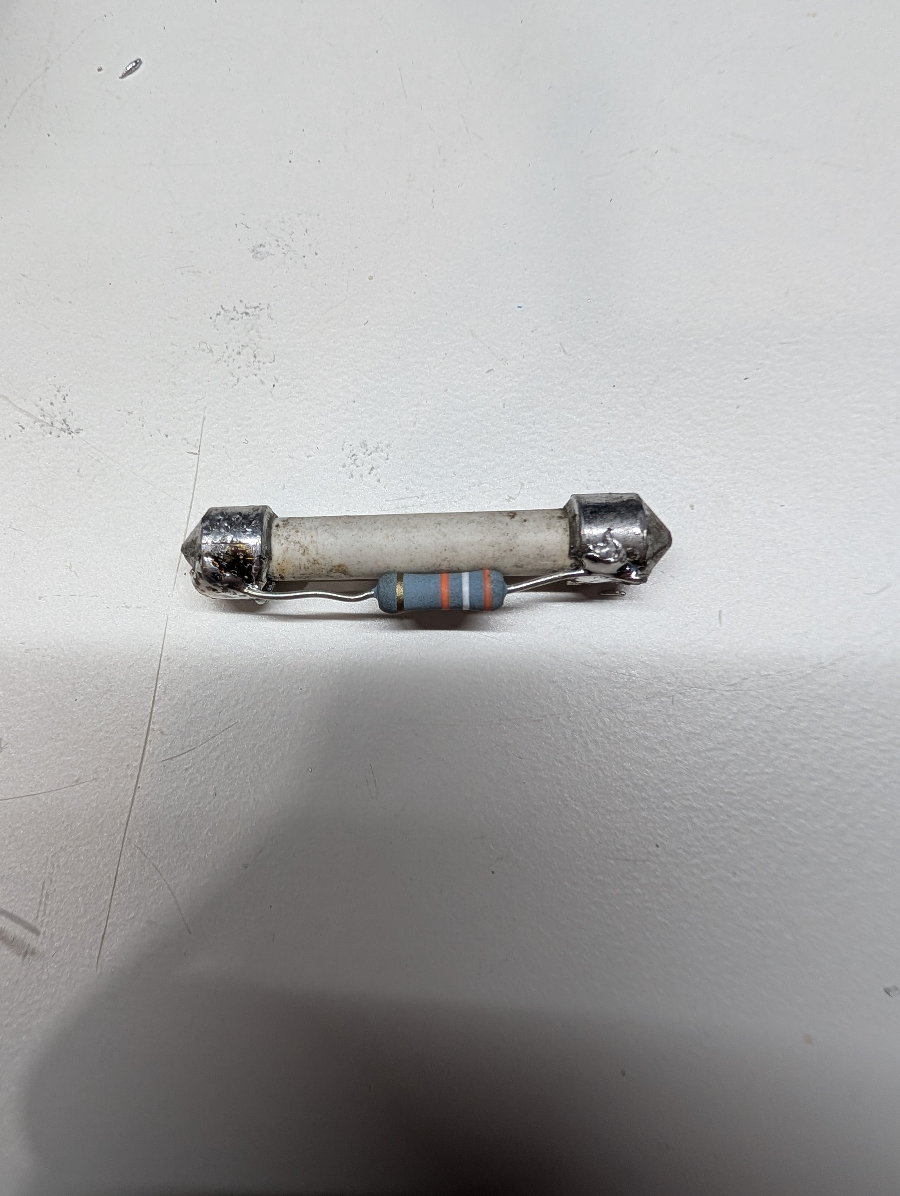
Then I soldered them back (the caps were already soldered and re-soldered to, so they are abut ugly) and, after having manufactured the insulating pressing gaskets from fishpaper (there was one original, but it was brittle, and I need two with extra resistors soldered) I put the back.
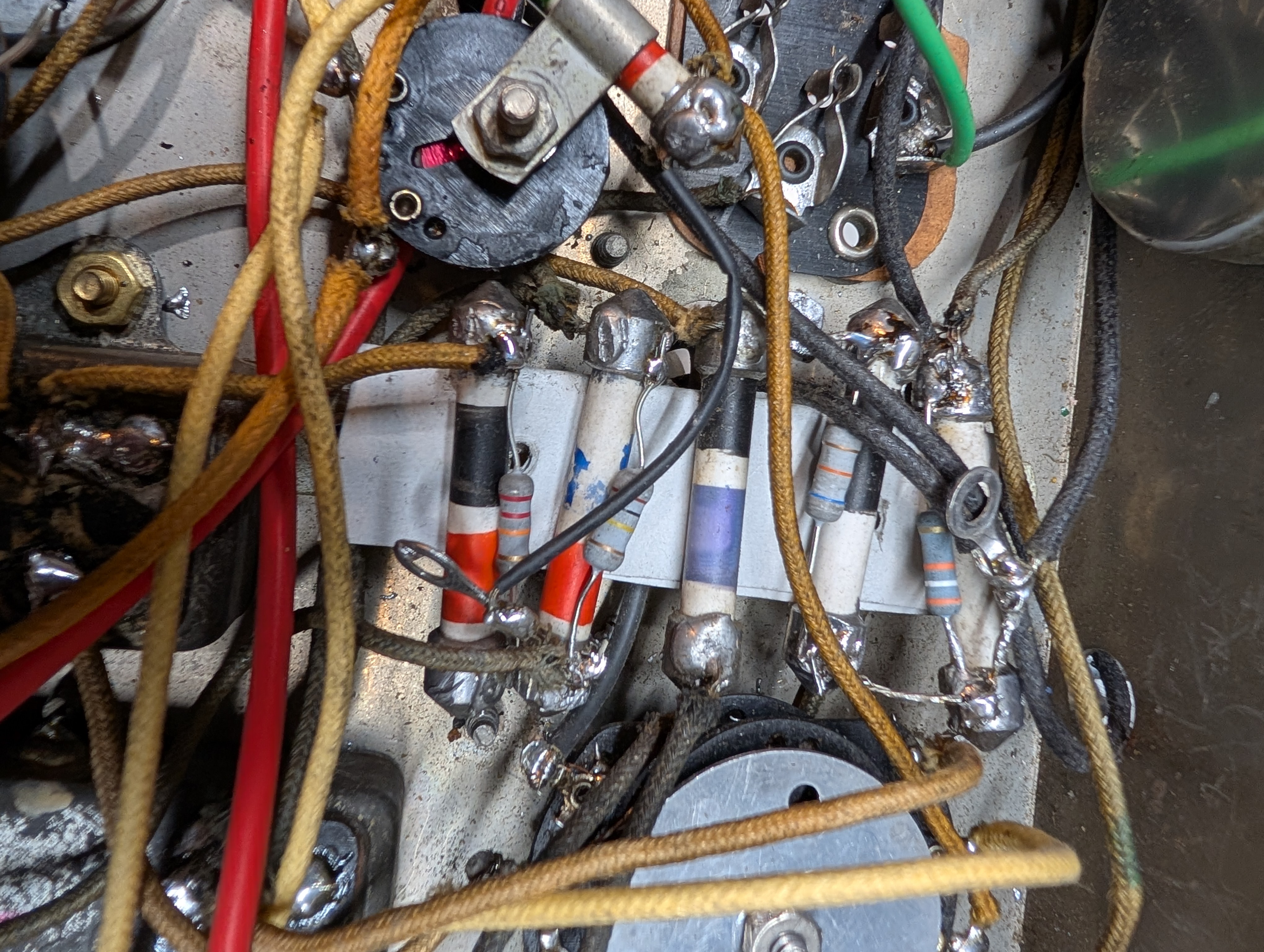
Then I eventually powered the radio up, and heard nothing but hum. The signal from the generator would not come through. Neither IF, nor the BC frequency.
The oscillator was fine, and the rest of everything checked out fine.
Then I put the scope on the 2nd detector Grid cap...it showed good signal when the radio was tuned to the frequency. All of a sudden the modulating beep slowly rose up and the signal became large.
I was able to tune the local station.
Then I removed the scope clip from the Grid cap, and the signal slowly faded away.
I am not sure what I did, but eventually the signal stayed.
So I removed the tubes, took Qtips, D5, and cleaned every single tube socket pin and tightened those that I thought were too wide.
Will let it dry and retry tomorrow.
The signal has some distortion. There could be two reasons:
1. The AK uses Plate detector
2. The speaker has been repaired (the cone), and the adhesive seems to be tar. I might procure a newer speaker or send this one for being re-coned.
People who do not drink, do not smoke, do not eat red meat will one day feel really stupid lying there and dying from nothing.
Posts: 16,524
Threads: 573
Joined: Oct 2011
City: Jackson
State, Province, Country: NJ
OK, it worked, but there is that hum issue.
I traced it to the balancing resistors from the 47 tube's filament to GND.
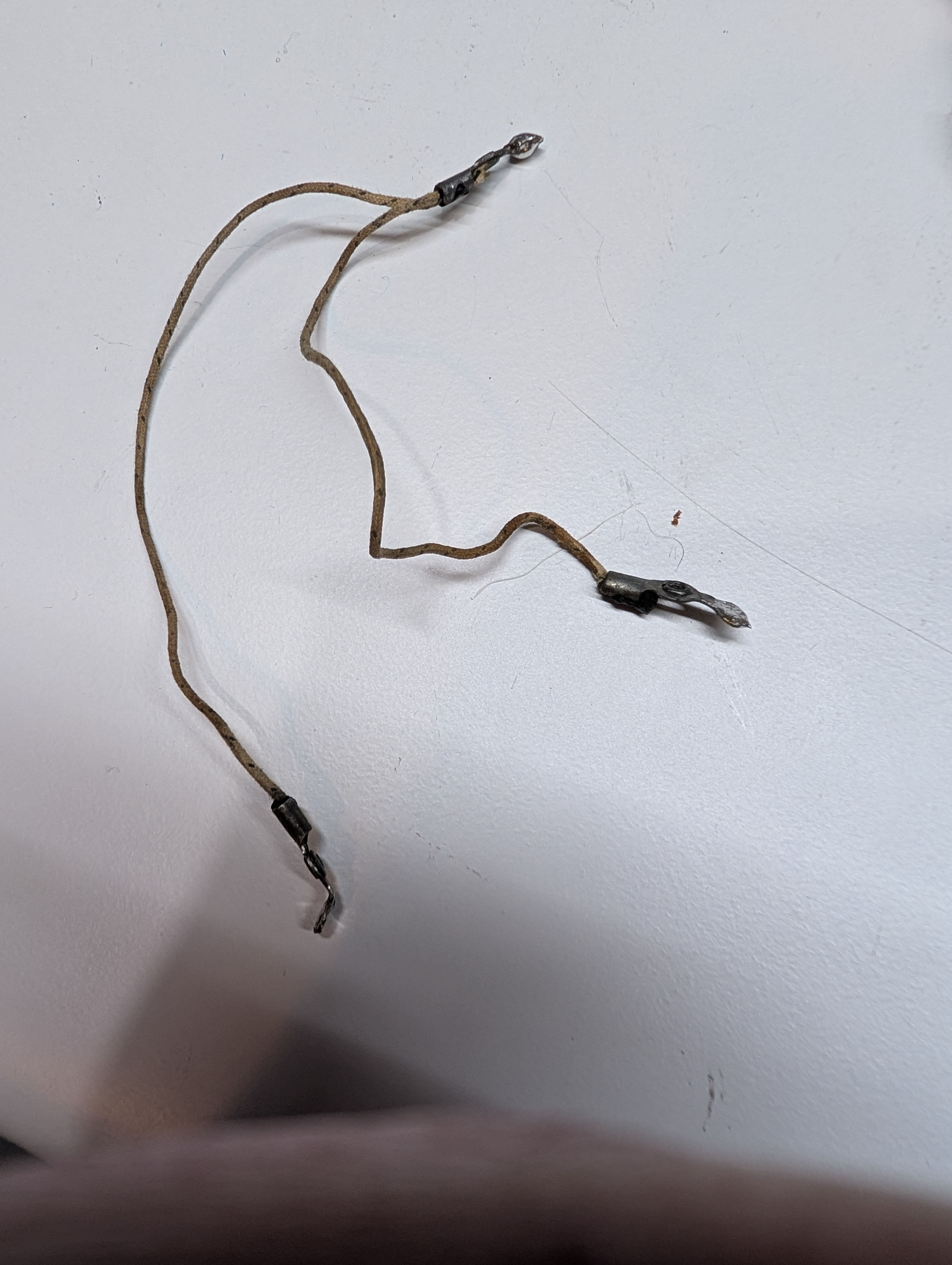
They are supposed to be 10 ohm (the sch shows that).
Removing the GND center removes the hum almost completely, but, of course, it is not right as the filament should be referenced to GND.
When I desoldered one resistor, it showed 5 Ohm from the center, and the one I did not desolder was 10 Ohm from the same point.
Upon desoldering it, both became 5 Ohm. The fact it was soldered by one end could not change that.
So, I am hesitant to solder it back as I suspect there is some issue in the resistive wire going to the lugs.
I have ordered 10 ohm resistors and will solder them instead tomorrow.
People who do not drink, do not smoke, do not eat red meat will one day feel really stupid lying there and dying from nothing.
Posts: 16,524
Threads: 573
Joined: Oct 2011
City: Jackson
State, Province, Country: NJ
Today the 10 Ohms resistors came (It might've meant in the sch it was 10 ohm total), and soldering them in improved things a bit.
I wiggled the originals and one of them does show fluctuations in resistance.
The hum periodically produced some more buzzing sound.
I looked in my stash and found a couple more of 47 tubes.
Checked them, both are nice.
Re-checked the one from this radio, and it is fluctuates: the value goes up to 1,200 and then goes down to like 700 and back, slowly...not so with the other two.
So, I put them in one by one, and that periodic buzzing component went away.
I unsoldered the voice coil and connected an 8 ohm (yes I know) speaker to it, and heard the same quality of sound with the distortion on the lower spectrum of music, which I was trying to figure out, if it could be attributed to the cone repairs. Nope. They could not.
Then I decided to turn on my 82 I repaired 2 or 3 years back.
I hear the same exact hum and the same exact distortion.
Actually, late version of 84 and the 82 are exact same radio, with AFC tube added to 82; Otherwise the sch is even drawn the same.
But the early 84 is also the same, with 24A tubes instead of 35. So, no wonder that they suffer from the same ailments.
(And 82 specifically says about the flex resistor "10 ohm TOTAL") which tells me that yes, the halves should be 5 ohm each. Not sure it matters much.
I will wait for a few days and, if I do not come up with a plan to tame the distortion, I will align it and be content.
People who do not drink, do not smoke, do not eat red meat will one day feel really stupid lying there and dying from nothing.
Posts: 16,524
Threads: 573
Joined: Oct 2011
City: Jackson
State, Province, Country: NJ
Found this
https://antiquewireless.org/wp-content/u...del_84.pdf
It says the same thing:
Filament Balancing Pot
When the set is tuned off station, there is enough gain so that you hear a small
hum. This hum has nothing to do with filter capacitors; it is due to capacitive pick up
from the filament/heater circuits. I found it loud enough to be annoying.
There is a way to reduce this hum that has been used in audio amplifiers for many
years. A small pot is connected to the two sides of the filament/heater circuit and
the arm of the pot is grounded. The pot is adjusted for minimum hum. Adding this
pot balances the ac pickup on one side of the circuit against that from the other
side, effectively nulling it out.
An incentive to make this addition is that local Radio Shack stores stock 25-ohm 3-
watt pots that are ideal for this application (Catalog number 271-265). Purists will
have to decide whether it is ok to add something to the radio that was not there
originally
-----------------------
I thought of the same and since before yesterday trying to get an offer through on some 10 ohms 5W small pots. Those are the cheapest I found. But my guess was correct: the hum is inherent to the circuitry.
People who do not drink, do not smoke, do not eat red meat will one day feel really stupid lying there and dying from nothing.
Users browsing this thread: 3 Guest(s)
|
|
Recent Posts
|
|
Philco 370LZ chair side not a 71LZ
|
| Can you send a couple of pictures?slford310 — 07:11 PM |
|
Philco 370LZ chair side not a 71LZ
|
| Thank you for the reply. After much studying I figured it just sat there and you have to open the top and pull up and/o...Villager61 — 06:42 PM |
|
Philco 370LZ chair side not a 71LZ
|
| Sorry, I haven't gotten to this project yet, so I don't have the answer, but I bet one of the experts on this site does....slford310 — 05:54 PM |
|
Value of capacitor
|
| That’s what I thought, but when I’m undoing 50 years of “repairs” it never hurts to check. Thanksbridkarl — 04:03 PM |
|
Value of capacitor
|
| According to AI, "Yes, you're reading that correctly. A .005 capacitor typically refers to 0.005 microfarads (µF), ...HowardWoodard — 03:57 PM |
|
Value of capacitor
|
| I’m having to replace this audio coupling cap between the plate of a 6F6 and a phone jack.
The parts list just says .005...bridkarl — 03:45 PM |
|
Philco 50-295 antenna connections
|
| Shoot, just realized that the blue wire connecting to the top of the tuning cap can't go to terminal D since that's on t...keith49vj3 — 01:20 PM |
|
Philco 50-295 antenna connections
|
| I forgot to mention that the IF and audio stages for AM work and FM plays great. Really confused by the antenna set up....keith49vj3 — 01:16 PM |
|
Philco 50-295 antenna connections
|
| All, I picked up a Philco 50-295 for a couple of dollars so I could demo sweep alignments for folks in my radio club. T...keith49vj3 — 01:14 PM |
|
Philco newbie with P-1891-WA console questions
|
| Hi Jeffcon,
First off, Welcome to the Philco Phorum!, a Phamily Phriendly Phorum, Phull of Phine Phriendly Pholks and ...MrFixr55 — 07:53 AM |
|
Who's Online
|
There are currently 2353 online users. [Complete List]
» 1 Member(s) | 2352 Guest(s)
|
|
|

|
 
|


![[-] [-]](https://philcoradio.com/phorum/images/bootbb/collapse.png)


