Posts: 202
Threads: 45
Joined: May 2023
City: Pocatello
State, Province, Country: idaho
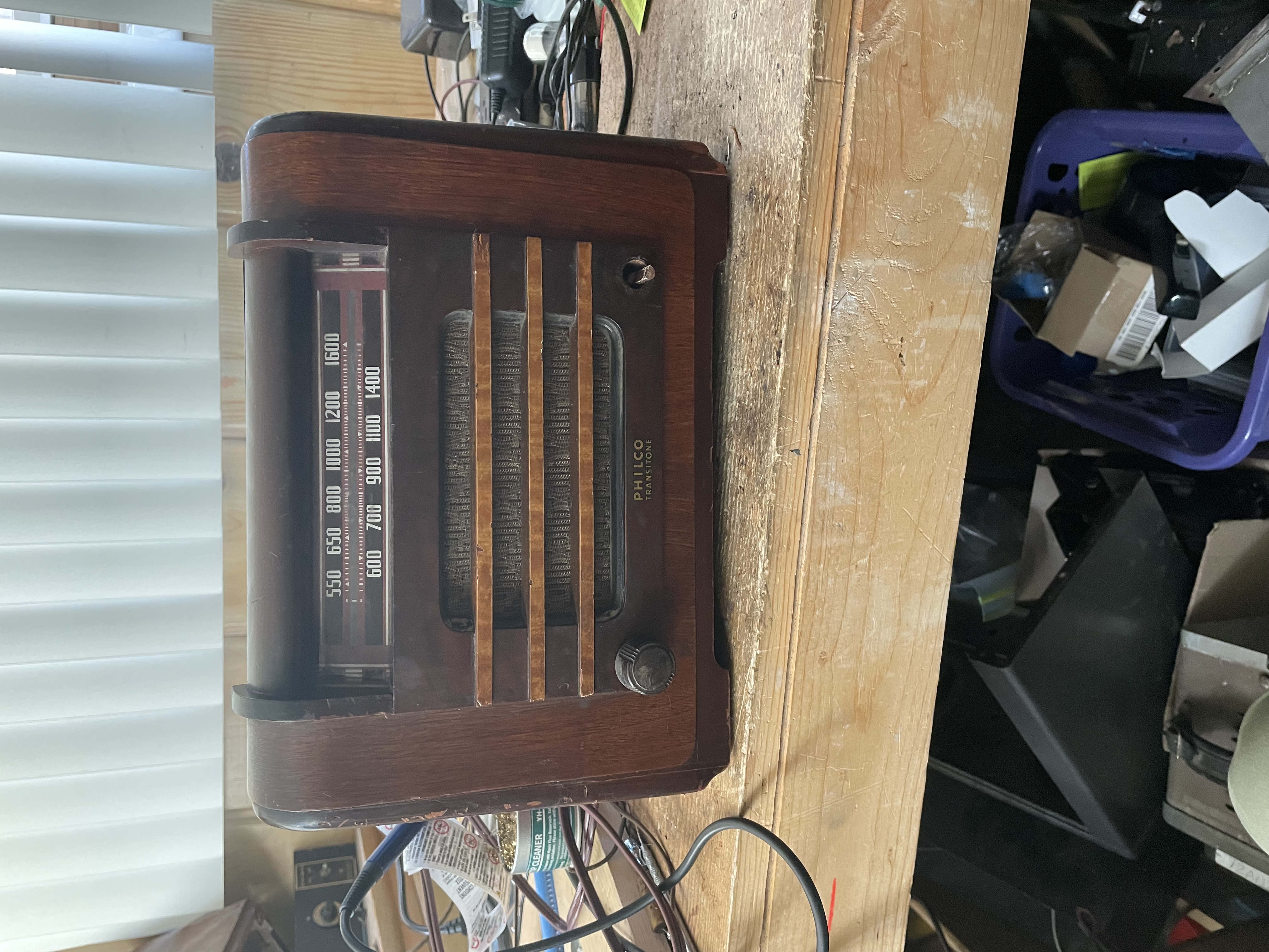
All recapped and checked. Had to order a new knob. Seems to work ok.
The bulb seems to be an issue. It’s bright for a moment and then gets truly dim. Seems to be drawing too much B+. I haven’t replaced any tubes so that may be the issue.
I also couldn’t figure out if the original power cord went under OR through the antenna. I put it under using a polarized cord with the hot side to the switch. I’m debating if it needs a fuse, but since I use it through a fused isolation transformer I think not.

(This post was last modified: 04-20-2025, 03:57 PM by bridkarl.)
Posts: 287
Threads: 16
Joined: Jan 2024
City: Tulsa
State, Province, Country: Oklahoma
Fantastic progress so far! You bring up an interesting question regarding fusing. I don’t hear much about people fusing transformer less AC/DC sets. Maybe I just haven’t happened to catch those particular conversations, I don’t know. But I’ve long wondered.
Does the bulb remain bright if you pull the 35Z3 tube? You won’t get any plate voltage if you remove this tube, but the rectifier is really the only thing I can imagine would suddenly dim the bulb, once it heats up and starts rectification.
Joseph
Philco 46-480
Philco 49-906
Posts: 202
Threads: 45
Joined: May 2023
City: Pocatello
State, Province, Country: idaho

the bulb is acting as a current limiter. Sort of a cheap solution to save the rectifer and the power supply filter. I’m thinking there’s some better solution.
I’ve used an inline fuse in the hot side of the switch before. Not sure it’s worth it given there’s a fuse on my isolation transformer, but if they have one at Ace Hardware next time I’m there…
Not sure what else this needs aside from an alignment. I haven’t swapped out tubes yet
(This post was last modified: 04-20-2025, 06:06 PM by bridkarl.)
Posts: 4,901
Threads: 54
Joined: Sep 2008
City: Sandwick, BC, CA
I have heard of some people adding current limiting resistors ahead of the heater string in AC/DC sets but I never bothered, I don't use most of them enough to blow out tubes anyhow. The last tube I had fail was after the radio had been on for an hour, and it wasn't even at one end of the heater chain, nor did it go open until after I tried checking it in a tube tester. There were a lot of dodgy components used in post war sets, and this one was from 1947-48, including tubes sometimes, I think the PT6 was a 1940 model was it not? I like the design of the cabinet by the way, clean yet elegant.
Regards
Arran
Posts: 202
Threads: 45
Joined: May 2023
City: Pocatello
State, Province, Country: idaho
It’s a 1941 model. I won’t be using it enough to justify figuring out.
All that’s left is getting the knob I have on order and figuring out what size screws I need to hold the chassis in the case.
I suppose a thermistor in series with the bulb might work but what value??
(This post was last modified: 04-20-2025, 06:41 PM by bridkarl.)
Posts: 872
Threads: 50
Joined: Feb 2013
City: Shenandoah,
State, Province, Country: Pennsylvania
I don’t know exactly how dim your pilot gets but this is the typical of the response of many transformerless AA5s where the bulb, usually a #47, is in series with the filament string and across a portion of the rectifier filament and plate of the rectifier. When first switched on, the filaments are cold, thus at a low resistance for a bit. The bulb flares up bright but then dims down as the filaments heat up and increase in resistance. Then the tubes start to conduct and draw current through the rectifier and the bulb so the brightness comes up slowly. From what I’ve seen, it doesn’t get as bright as it does when first switched on and filaments are cold.
Ron
Bendix 0626. RCA 8BX5. RCA T64
Philco 41-250. Philco49-500
GE 201. Philco 39-25
Motorola 61X13. Philco 46-42 Crosley 52TQ
Philco 37-116. Philco 70
AK 35 Philco 46-350
Philco 620B. Zenith Transoceanic B-600
Philco 60B. Majestic 50
Philco 52-944. AK 84
Posts: 287
Threads: 16
Joined: Jan 2024
City: Tulsa
State, Province, Country: Oklahoma
I agree with Ron. That’s how my 49-906 behaves. That’s why I’m curious if the bulb stays at full brightness if the rectifier tube is pulled.
Joseph
Philco 46-480
Philco 49-906
Posts: 202
Threads: 45
Joined: May 2023
City: Pocatello
State, Province, Country: idaho
I’ll get on doing that and see what happens.
Just to keep this all in one thread -
Anyone know what length/size is used for the screw holding the chassis on And any recommendations for touch up paint for the black trim? I have several Philcos with that black edging.
Posts: 4,901
Threads: 54
Joined: Sep 2008
City: Sandwick, BC, CA
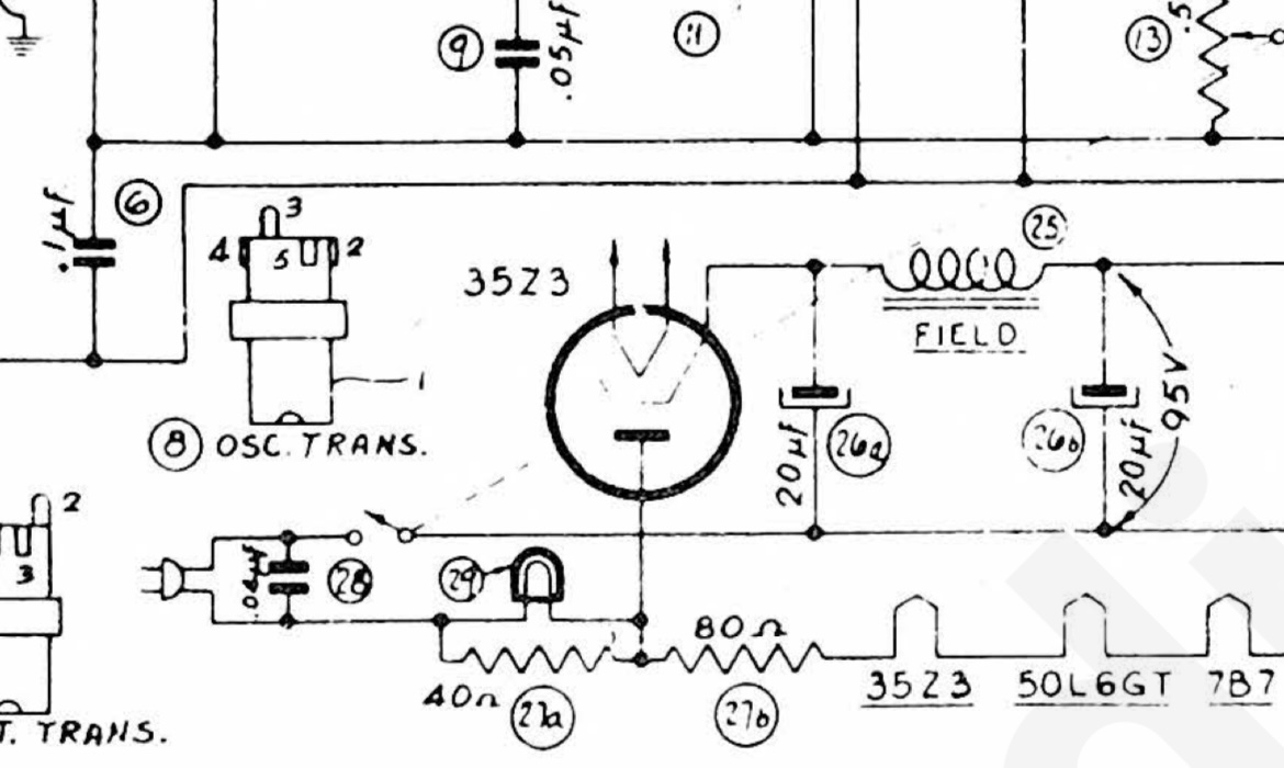
Well the 35Z3 doesn't have a tap on the tube heater for a pilot light, so in this set they have the dial lamp paralleled with a 40 ohm power resistor, between the hot side of the power line and the plate of the 35Z3. In some sets, like my 42-327, they used a 120 volt candelabra bulb across the power line to light the dial, and basically the whole back of the set for that matter.
As for the cabinet trim it's probably medium walnut or dark walnut shading lacquer that was used, Mohawk paint makes both of these in dye and pigment based varieties. If it really was black then lacquer or acrylic paint will work, as you can coat over either with clear lacquer.
Regards
Arran
Posts: 1,257
Threads: 11
Joined: Jul 2020
City: Greenlawn
State, Province, Country: NY
Hi Gang,
Tube heaters are not "Ohmic" devices (that maintain specified resistance over wide temperature, current, etc.). They start out at a very low resistance and draw a lot of current. If you observe the filaments, it is possible that you will see a similar but less dramatic effect on some of the tubes. Every AA5 set I have with a pilot light behaves the same way, with the bulb getting very bright at turn on, dimming as the tubes warm up and then getting brighter as the rectifier starts conducting.
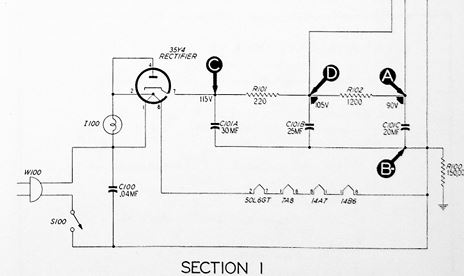
As for fusing, most sets using a 35Z5, 35W4 or 35Y4 (the ones with the tapped filament heater) puts the rectifier plate (and the B+ load on the tap. A short in the B+ or heaters in the other tubes would blow the section of the 35Z5 heater between the power input and the plate (and also the pilot lamp).
Attached below is the Power Supply section of my 47-205 that uses a 35Y4 in the manner described above. No resistors are used because the convertor, IF and detector / 1st AF are 14V tubes, so the total filament voltage of the string is 127V nominal. See below:

In your set, the 35Z3(a Loctal) tube does not have the tap that a 35Z5 does. In addition, since the convertor, IF and detector / 1st AF tubes are 7V types, you need the 120 Ohms that the Candohm resistor, #27A / 27B provides. Since the 35Z3 is part of the heater string, pulling the tube not only breaks the B+, it breaks the filament string, therefore no current will flow and the pilot remains off. IMHO, the Candohm acts as a fuse (albeit an expensive and had to replace one) in a manner similar to a 35Z5 filament as described above.
Hope this helps.
"Do Justly, love Mercy and walk humbly with your God"- Micah 6:8
"Let us begin to do good"- St. Francis
Best Regards,
MrFixr55
Posts: 4,901
Threads: 54
Joined: Sep 2008
City: Sandwick, BC, CA
Actually the Loctal tube series, with number beginning with "14" are 12.6 volt tubes, at 150 ma, I'm not sure why Sylvania did this anymore then why the ones beginning with a "7" are actually 6.3 volt tubes. To make matters more confusing Sylvania made some 6.3 volt loctals in their "7" series with 150 ma heaters, like in the PT6, but there were others that had 300 ma heaters as well.
Regards
Arran
(This post was last modified: Today, 02:14 AM by Arran.)
Posts: 1,257
Threads: 11
Joined: Jul 2020
City: Greenlawn
State, Province, Country: NY
Hi Arran,
Yes, you are correct, the "nominal" voltage for these Loctal tubes was the same 6.3 or 12.6 V as the other tubes whose numbers began with either 6 or 12.
My guess is that the Loctal tubes were meant for auto radios. Since a car electrical system could run as high as 7.2V or so for 6V systems and 14.5V or so for 12V systems, this may be the reason for the nomenclature used for the 7 and 14 Loctal tubes. Note that the first number, denting heater voltage was not changed for the 35V and 50V tubes between Octal and Loctal tubes. Granted that the stated voltages for these "7" and "14" tubes are the same 6.3 and 12.6V as the tubes that they replaced, but I believe that when the original tubes were released for car radio use, they had wider filament specs than other tubes. I don't know if these "7" and "14" numbers came into existence because type numbers in the "6" and "12" range were already reserved for the plethora of tubes to be introduced in the late 1940s and early 1950s.
Since Philco became a major supplier of automobile radios, Philco was an early advocate of using these 6V tubes, originally designed for DC filament or heater operation in car radios, in home radios, supplying these heaters with 6.3VAC, while others, especially RCA, advocated for the series of tubes using 2.5V AC heaters. this allowed Philco to keep a trimmer tube inventory than RCA and others who were making both home radios using 2.5V tubes and car radios using 6V tubes. Philco was also an advocate of the Loctal tube types that Sylvania was introducing, even using them in their TV sets where locking in the tube to prevent it from being dislodged by vibration was not a particularly big issue.
I would guess that some of the "7" tubes had 150 mA filaments for both economy (less power draw) and for compatibility with the 150 mA heater strings that the AA5 sets started using with the development of the 50L6 / 50A5 and the 35Z5 / 35Y5 to eliminate ballast resistors and "curtain burner" power cords.
"Do Justly, love Mercy and walk humbly with your God"- Micah 6:8
"Let us begin to do good"- St. Francis
Best Regards,
MrFixr55
Users browsing this thread: 1 Guest(s)
|
|
Recent Posts
|
|
Electrolytic restuffing/internals
|
|
Did as suggested. Cut can with hacksaw, removed internals, attached new 8mf cap - with ample use of cardboard and elec...bridkarl — 03:36 PM |
|
The list of my radio & TV collection!
|
| For fans of antique radio...
My new video...
How to test radio tubes on a Hickok 530B tube tester?
Test radio tubes o...RadioSvit — 01:25 PM |
|
philcorepairbench.com - shadow-meter
|
| Thank you
Billpoulsbobill — 11:53 AM |
|
philcorepairbench.com - shadow-meter
|
| Hi, Try here
Philco Service Hints & Tips, Number 1
It's from the web archive (Way Back Machine).Keith — 10:17 AM |
|
PT-6 finished!!
|
| Hi Arran,
Yes, you are correct, the "nominal" voltage for these Loctal tubes was the same 6.3 or 12.6 V as...MrFixr55 — 07:48 AM |
|
PT-6 finished!!
|
| Actually the Loctal tube series, with number beginning with "14" are 12.6 volt tubes, at 150 ma, I'm not sure ...Arran — 02:14 AM |
|
philco predicta
|
| The model is the holiday without UHF It has no sound and I don't have an oscilloscope or signal generator.cgl18 — 08:51 PM |
|
Philco model 38 code 121 not receiving signal.
|
| I will definitely check my lead length and wire dressing. Thanks for the ideas.Stormlord5500 — 08:06 PM |
|
Philco model 38 code 121 not receiving signal.
|
| Do make sure that you twist the 3 wires from the chassis to the transformer, and dress away from tubes, especially audio...MrFixr55 — 07:38 PM |
|
Philco model 38 code 121 not receiving signal.
|
| The cone unfortunately got damaged when I removed it. The glue that held the cone to the basket was sloppily applied and...Stormlord5500 — 07:12 PM |
|
Who's Online
|
There are currently 826 online users. [Complete List]
» 1 Member(s) | 825 Guest(s)
|
|
|

|
 
|


![[-] [-]](https://philcoradio.com/phorum/images/bootbb/collapse.png)


