Philco 42-345 Restoration/Repair
Posts: 17
Threads: 2
Joined: Mar 2025
City: Bristol
State, Province, Country: VA
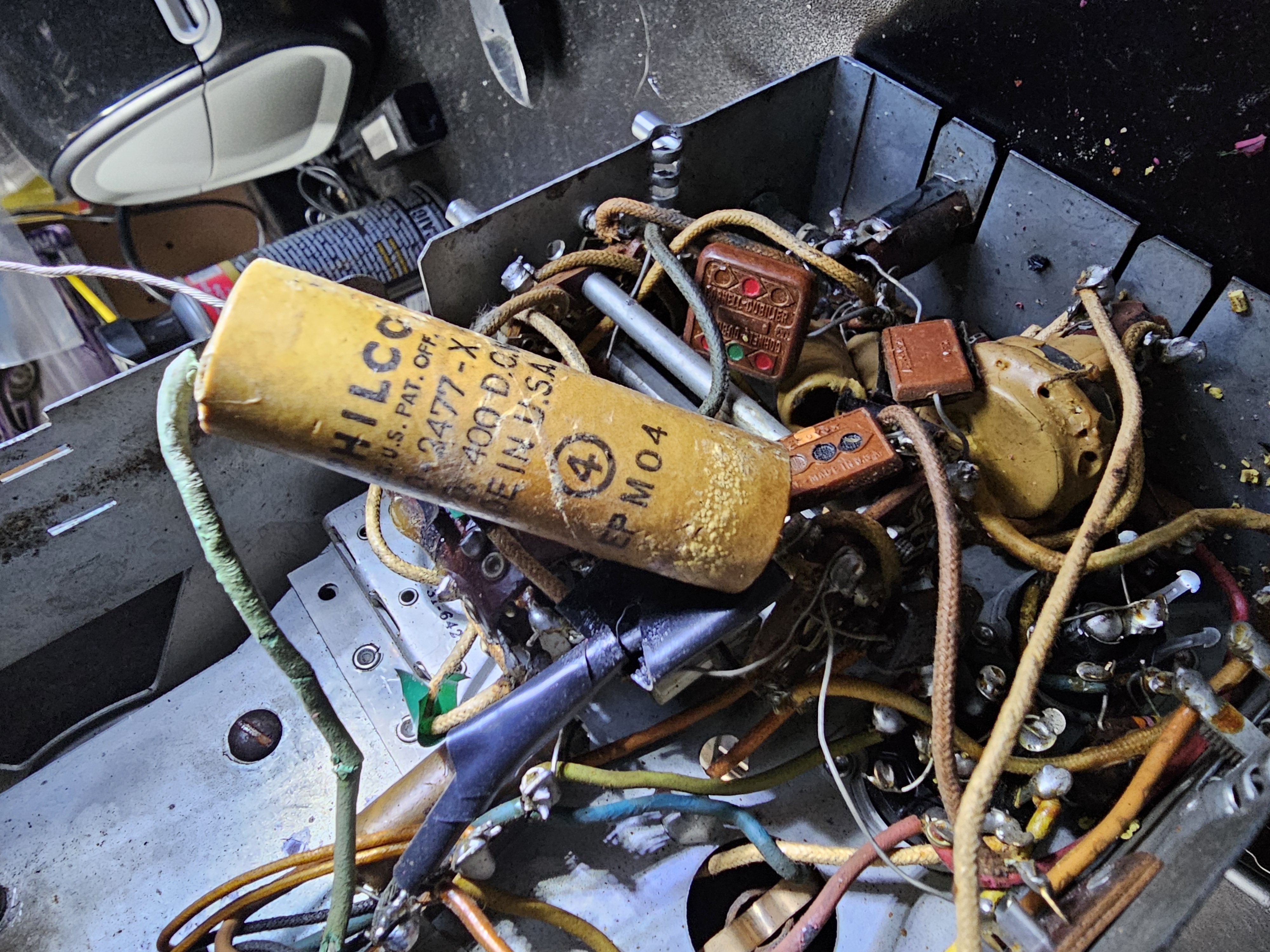
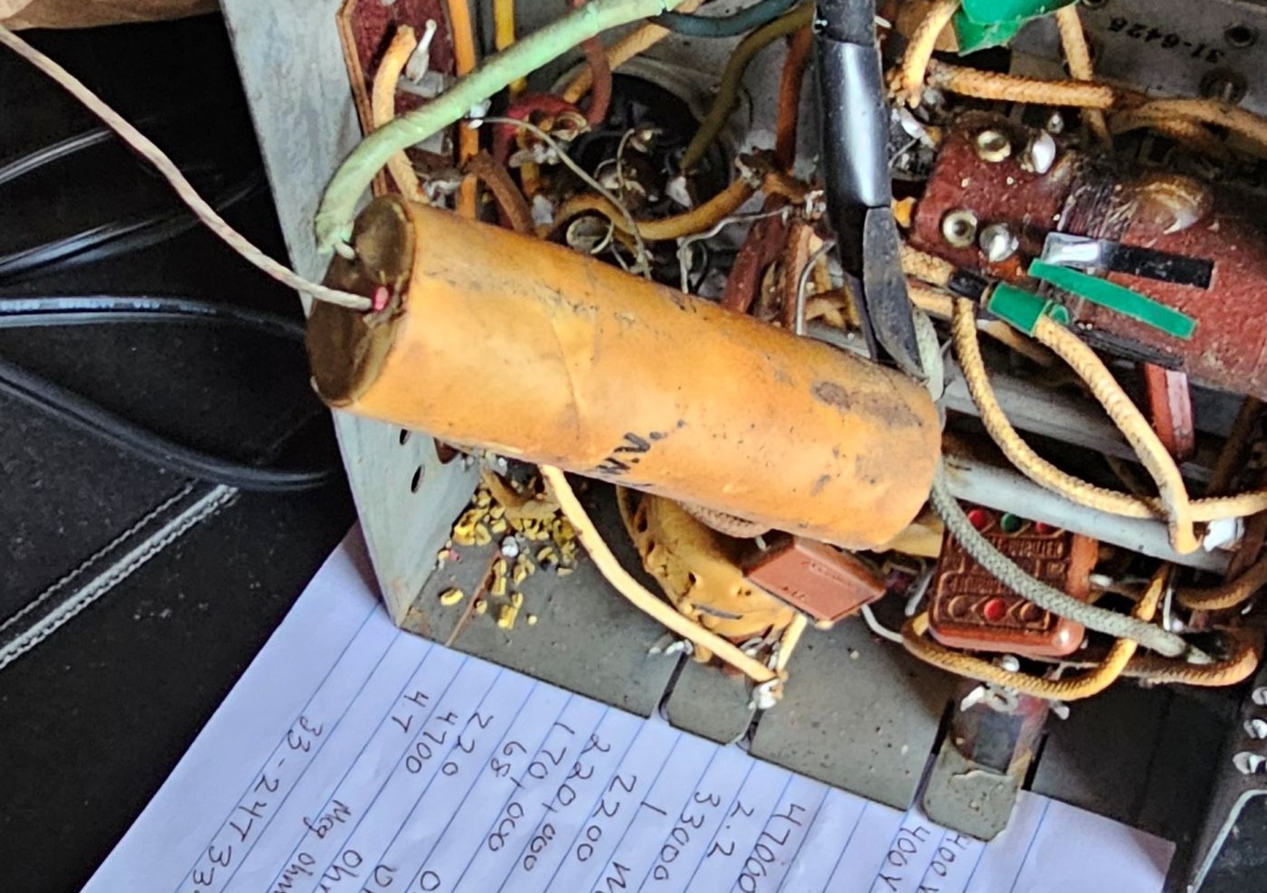
Can anyone help me figure out a capacitor that has 3 wires coming out of it red and green on one side and a black wire on the other. I seem to only find ones with 2 wires and not sure about the difference. It's a Philco 400V, 4-4 MFD. I will try and include a photo.
Thanks,
Guys

Posts: 1,153
Threads: 47
Joined: Feb 2015
City: Roseville, MN
That's a dual 4 MFD, red and green are both 4mfd and black is common negative. You should be able to see them in the power supply circuit of the schematic diagram.
Posts: 28
Threads: 3
Joined: Apr 2025
City: SPRUCE GROVE
State, Province, Country: Alberta
Regarding picture 5 on page 1 of this thread this capacitor is #40 on scematics diagram - 4mF+4mF. Black wire is "-" (grount), red and green "+".
But it look like this capacitor was dead and as parralel was soldered two another, in blu and metal.
My advice - foud two new capacitors 4mF x 400V. It may be very small. And restore old as I present in my message here:
https://philcoradio.com/phorum/showthrea...#pid206311
[Image: https://philcoradio.com/phorum/attachment.php?aid=32368]
Posts: 17
Threads: 2
Joined: Mar 2025
City: Bristol
State, Province, Country: VA
Thanks, RodB and Vlad95,
I was mainly trying to figure out this capacitor to locate a replacement, Vlad thank you for reminding me of the blue capacitor which I almost forgot about being that I couldn't find it on the schematic. I was so busy trying to get the other unsoldered and forgetting the 2 were soldered to the same contacts. Seeing the blue capacitor and some taped wires and missing antenna tells me someone worked on it in the past. I do wonder if they started on it and gave up.
Vlad thank you for the link for restoring the old capacitor, I'm really not concerned about returning to original and wonder if I can just install the 2 capacitors separately. Which brings me to another question in regard to the blue capacitor it's 450V 8MFD, is having a capacitor with more MFD's bad for the radio? If the blue capacitor is ok to use, I can keep it connected and get another for where the green wire is connected from the old capacitor. Hopefully I am testing it correctly, but I have tried testing the old capacitor and not getting any reading.
Posts: 28
Threads: 3
Joined: Apr 2025
City: SPRUCE GROVE
State, Province, Country: Alberta
The more the better. (Within reasonable limits.)
2-5 times more is no problem in this case.
Posts: 17
Threads: 2
Joined: Mar 2025
City: Bristol
State, Province, Country: VA
Posts: 1,153
Threads: 47
Joined: Feb 2015
City: Roseville, MN
Yes, 57 is an electrolytic cap that should be 12 mfd 400 volts according to the parts list from the Phorum library schematic. Someone replaced it with the duo 20 mfd 150 volts and it looks like they used only one section. You can use 12 to 16 mfd 400 volts and the negative lead is not grounded. BTW the schematic I used is very clear.
Posts: 17
Threads: 2
Joined: Mar 2025
City: Bristol
State, Province, Country: VA
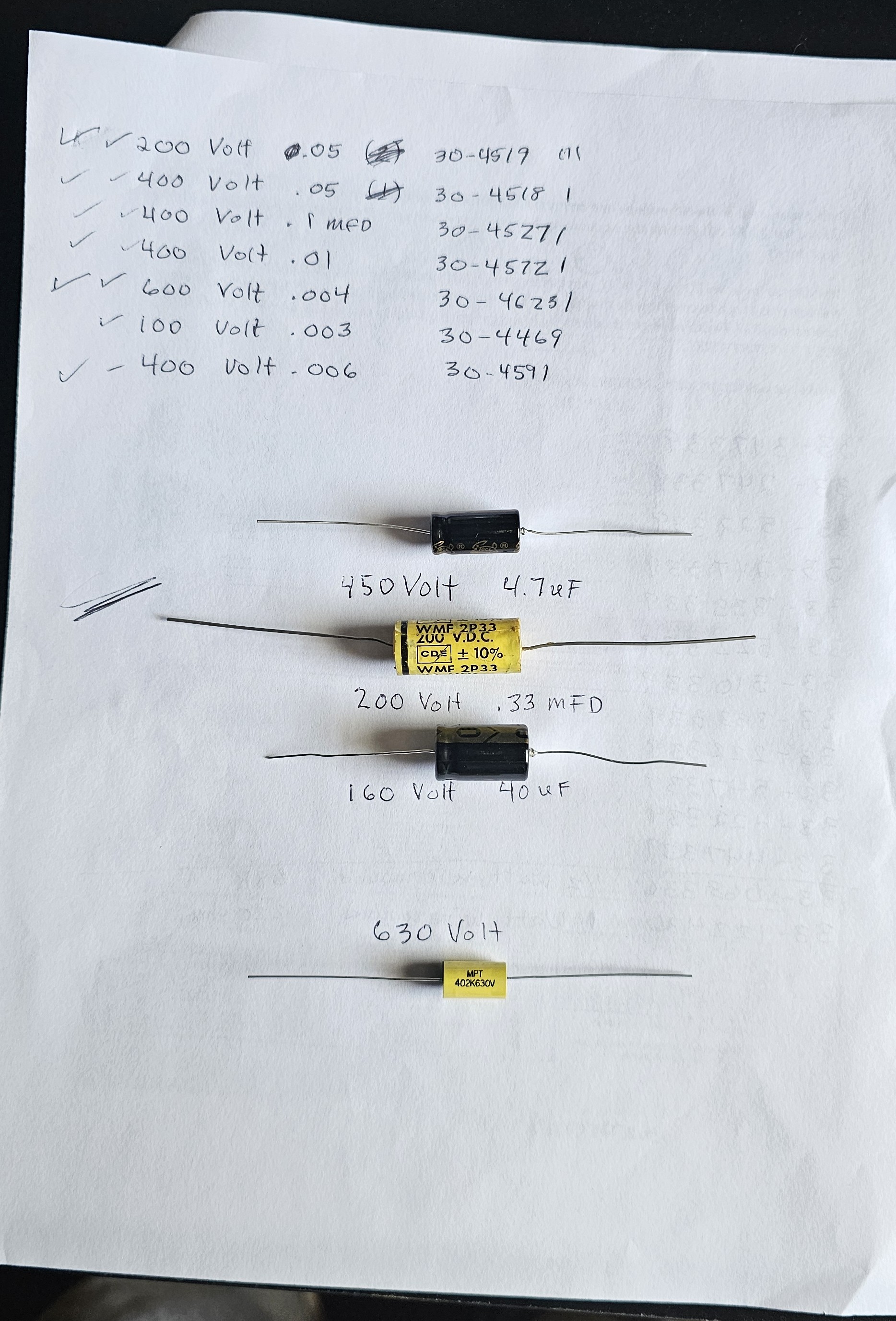
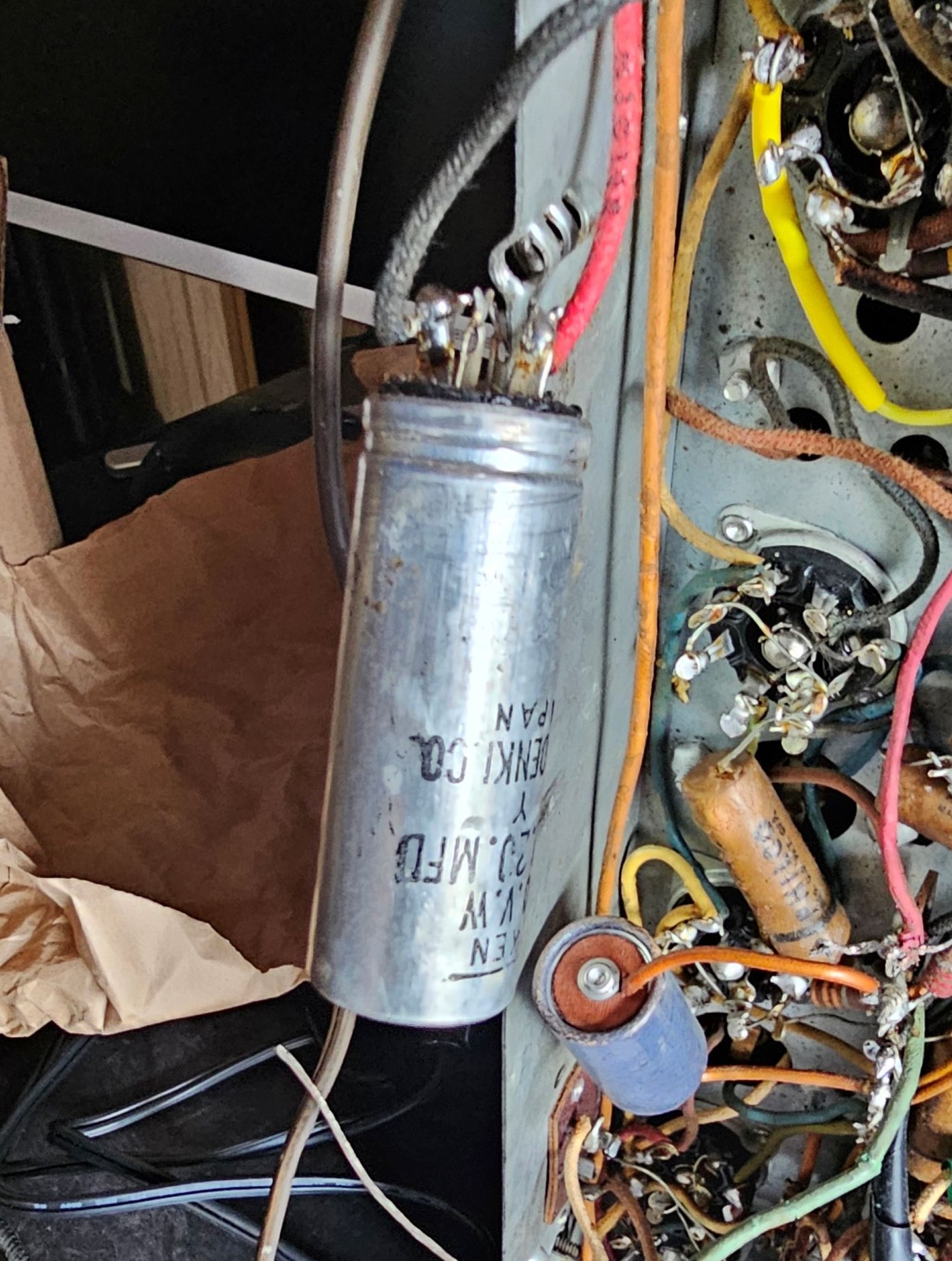
I have ordered and received new caps for this radio and hope I've ordered the correct ones. I tried matching them to the schematic as best as I could but matching the voltage was difficult, so I ordered ones with slightly higher voltages. They are also smaller in size based on the ones installed but I read that this is normal. I am attaching pictures and not sure about the big silver cap and a 400V cap in the picture. Does the silver cap need to be replaced with a large cap of the correct voltage (400V) as in the picture? also the dual 400V 4-4MFD tan paper cap which earlier was pointed out as possibly dead. The tan cap has a replacement blue 450V cap in parallel with it but probably the 2nd 400V is still needed


I am confused about the differences in Electrolytic condenser/capacitors and the metal vs paper material and the sizes.
Posts: 1,153
Threads: 47
Joined: Feb 2015
City: Roseville, MN
Hi, there's a lot to consider when designing these circuits so you shouldn't have a lot of concern when replacing caps. A lot of people concentrate on replacing them with exact values but remember that these circuits are 60-80 years old and when they were designed components had a 20 percent tolerance. Standard values for caps are different today than 60 years, or more, ago. So, a 0.05 mfd cap in your chassis is now a 0.047 mfd and 0.02 mfd is 0.022 mfd. These are all within tolerance of circuit design. You'll pay more for exact values than getting replacement values.
Electrolytic caps are manufactured for low frequency applications thus have higher capacity. In the old days they were made of paper impregnated with an electrolyte which apparently increases the capacity.
When you buy poly film caps you can get them all at 630 volts and you'll save some money because that is the most common voltage and manufacturers see this and give a price break when they can make them in bulk quantities. Also, if you have to buy 6 or more of a certain value you might as well get ten and pay less.
Quite often you will find that someone has either substituted a cap with a different value or wired in the new cap across the old one. In this case stick with the schematic. Either practice does not fix the problem and causes confusion. If a circuit calls for a 400 volt electrolytic then that voltage would be the same or higher for the replacement. Remember, the higher the voltage, the greater the size.
Hope this shreds some light on capacitors.
Posts: 272
Threads: 12
Joined: Nov 2005
City: Nashville, TN
Hi, all the caps I order, other than the electrolytics, are of the 630V rating. No worries on it being too high, and no reason to try and scrounge around to find a 200V, 400V 600V specific caps.
As mentioned, same with the values. Modern values are within 20% of original spec and will work fine. .022 for the .02 .047 uf for the .05. For what we do, they will work just fine.
The large silver cap can is not original, so you must remember to not base your order on what the non factory can says.
Look at the diagram and parts list. I see a couple other electrolytics that were not stock as well. Sometimes a later repairman may have wired something in with too high of capacitance.
I go by the diagram as you don't want to replicate a wrong value.
If I've repeated something that was already mentioned, I apologize. Good luck with your project!
Posts: 17
Threads: 2
Joined: Mar 2025
City: Bristol
State, Province, Country: VA
Thank you Rodb and Gary for helping with clarification on these capacitors. Other than the Tiny 630volt one I'm not sure about the others I'm hoping are OK. I was still questionable about the silver capacitor which should be 400volts but think I found a replacement, please correct if wrong. The original appeared to be a can type electrolytic capacitor clamped to the chasis. So does the replacement need to be a can as well? This is what confused me because the ones I already received are also called electrolytic capacitors.
Today I unsoldered one and only one capacitor, I think my soldering gun is crap or the original solder is made of steel ?. It was a pain getting lose in the tight space. But I checked a resistor that was attached to it and had zero reading so resistors are on order. The capacitor I started with is in the area with the double paper cap which appeared to possibly be dead. I am thinking there was an issue in that area worked on before.
Posts: 1,153
Threads: 47
Joined: Feb 2015
City: Roseville, MN
That silver can capacitor is an aluminum electrolytic. You should replace it with an aluminum electrolytic with the values from the schematic not from the part. I repeat, use the schematic to identify and replace capacitors. You can have the can capacitors specially made but you can get the same effect with the individual units for less than a couple bucks each. Technology has shrunk them, so don't expect to see the same size as what was there.
Resistors don't usually short to zero. They will measure high or open and sometimes measure low. I don't know what you mean when you say a capacitor is dead. Capacitors either get leaky, open or short. Quite often shorted ones explode.
Posts: 4,910
Threads: 54
Joined: Sep 2008
City: Sandwick, BC, CA
With regard to the speaker, unless the cone is so brittle that it crumbles as soon as you touch it I would try to repair it, oval speakers with a field coil are not exactly easy to get anymore. There are a few options to re-enforce the cone, you can coat it with fabric glue, contact cement, speaker cement, or Thompson's water seal. Very likely it will only need the tear/crack fixed, and a smear of glue over the area will fix that.
If your solder gun can't heat up the joints on the tube sockets and terminal strips, it may need the tip taken out, cleaned where it goes into the barrels, and retightened. The tips used on Weller soldering guns are kind of weak and break over time, I started using thick copper wire as a replacement, though I may try using steel wire from a coat hanger, all it needs is for the metal to be tinned. A lot of people like using soldering stations but I learned how to work on tube electronics with soldering guns, and old fashioned irons, and still use them. I use a 100 or 120 Watt iron for soldering to the chassis, you can still buy them new for stained glass work but I got mine at flea markets, swap meets, and garage sales.
Regards
Arran
Users browsing this thread: 1 Guest(s)
|
|
Recent Posts
|
|
Another amp build - here I go again!
|
| Well, never enough yet how much is too much? I ordered some spare parts from a couple vendors in China and now have ship...TV MAN — 10:49 AM |
|
A Marconi model 86
|
| This Marconi was a bit of a challenge. It was totally missing one electrolytic capacitor, and the photos show a couple ...Dan Walker — 10:48 AM |
|
Philco 42-345 Restoration/Repair
|
| With regard to the speaker, unless the cone is so brittle that it crumbles as soon as you touch it I would try to repair...Arran — 04:07 AM |
|
Philco 42-345 Restoration/Repair
|
| That silver can capacitor is an aluminum electrolytic. You should replace it with an aluminum electrolytic with the valu...RodB — 11:46 PM |
|
Philco 42-345 Restoration/Repair
|
| Thank you Rodb and Gary for helping with clarification on these capacitors. Other than the Tiny 630volt one I'm not sure...osanders0311 — 10:17 PM |
|
1949 Motorola 5A9M
|
| Hello All;
I found the CMB41L down in the basement, it is definitely a 1950-51 model, the capacitors have date codes ...Arran — 07:48 PM |
|
Philco 42-345 Restoration/Repair
|
| Hi, all the caps I order, other than the electrolytics, are of the 630V rating. No worries on it being too high, and no ...gary rabbitt — 05:46 PM |
|
Philco 42-345 Restoration/Repair
|
| Hi, there's a lot to consider when designing these circuits so you shouldn't have a lot of concern when replacing caps. ...RodB — 02:03 PM |
|
Philco 42-345 Restoration/Repair
|
| I have ordered and received new caps for this radio and hope I've ordered the correct ones. I tried matching them to the...osanders0311 — 11:35 AM |
|
Philco newbie with P-1891-WA console questions
|
| Hello Jeff ,
Far as the Electrolytic capacitors go here is a list of parts.
that will work . I like using Nichicon and...radiorich — 09:50 PM |
|
Who's Online
|
There are currently 1148 online users. [Complete List]
» 1 Member(s) | 1147 Guest(s)
|
|
|

|
 
|


![[-] [-]](https://philcoradio.com/phorum/images/bootbb/collapse.png)


