Hey all! Well, I guess that with what I learned from my last build, it's time to move up the ladder another rung and take a shot at a more powerful amp build. With mowing (and rain) season upon us, this will be a rather long build. Hopefully finished by fall. I'm hoping for around 50w out of this one using some of the common and good performing Dynaco circuit and readily available off the shelf current production parts that anyone following this thread can duplicate. I'm using a prepunched stainless chassis from over seas (eBay) which is attractive, inexpensive and comes with almost all the hardware you would need. It looks different than my previous builds and will be lightly modded in staying with a more traditional old school design. While sticking to a very common schemo, I am also looking at the Williamson and Mullard design, but with my limited socket holes (octal), I may try the Dyna circuit using a triode/pentode driver, and a par of 6L6GC outputs. This, as before, will be my design (with the assistance of others) using fixed bias and the KISS theory. I figure if Dynaco can get 60w out of this simple circuit, I should be able to get 50w using similar design, transformers, voltages and currents.
As of this writing, I have the layout of the major components in place and it will be built similar to my previous attempt. I'm using a beefy Hammond PT with enough juice to put my voltages in the mid/high 400v range with 200+ma force. Enough filament for 20 tubes and 5 rectifiers (alright, maybe one current hungry 5R4 and a handful of sound bottles) and a nice affordable 50w UL, 5k output tranny. Yeah, it's from overseas (also eBay), but on some initial live power tests sounds very "alive". Trying to keep costs down and quality up. Most of the parts virtually bolted right in place with a half dozen new holes drilled to make it right. So far, very simple and straightforward. Sure, nitpickers will see some errors, but for a prefab, this is very affordable and works nicely with my choice of iron. Ok, so just how am I gonna use triode/pentode drive in an octal hole? Well, a nice little 9pin to octal adapter! Oh no, not one of those hobcob socket adapters that sticks up 2" with a variety of different sockets hanging out the top! Nope noooo, this is a real adapter that allows me to screw a 9pin socket into an octal hole! And, I think it looks "factory"!
Now, this is NOT a kit, nor is it a sacrificed/modded kit. This is a fresh, ground up build and has been a goal of mine since a youth. And yeah, it'll be a pair of mono blocks.
Anyway, below are a few pics of the proposed build to date, and will be a rainy day project through the summer. Yes, I have powered things up and "hum tested" to check the placement of my transformers. Even a 1/16th inch movement makes a difference (PT powered up and headphones connected to speaker wires).
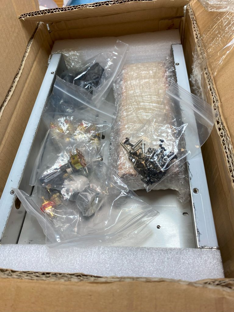
Chassis kit. This came with bottom, wood sides, speaker posts, power cord & plug, line control, feet, knob, screws, input jacks - just about everything exc tube sockets and components. It's a little narrower than the kits, but deeper and thicker.
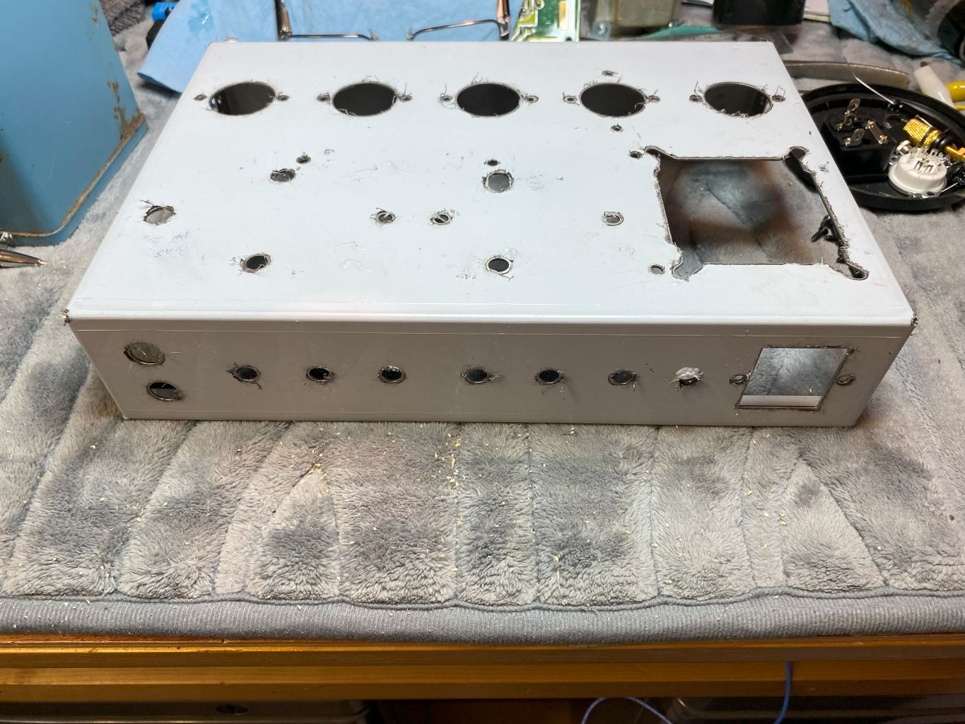
Holes drilled
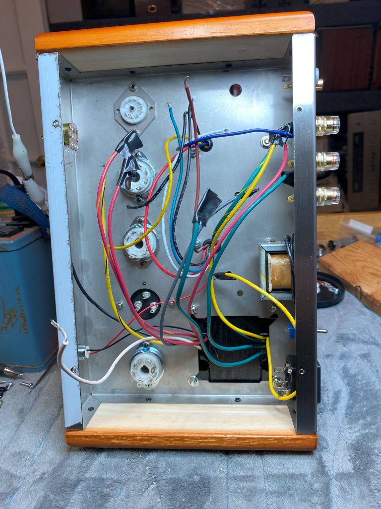
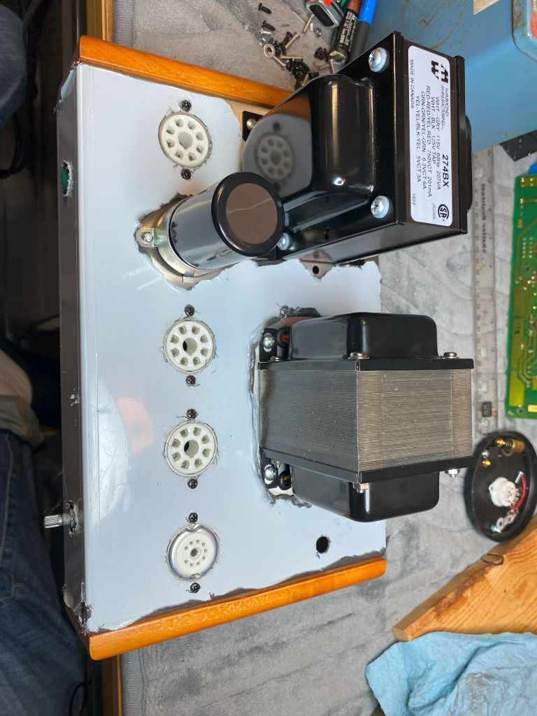
My choke screwed perfectly to to the inside rear of the chassis, and the power trans covers the recess hole for the laydown trans designed for. Had to trill a couple mounting screw holes. The output tranny lined up almost perfect, however I did also have to drill a couple mounting screw holes and enlarge a hole to allow the primary wires to pass through the chassis. The secondary used the existing hole (and grommets). You can also see my socket adapter which sandwiches the 9pin bracket between the chassis and adapter and allows you to turn the socket any direction needed. It's solid and doesn't move at all. No mods to the chassis so if I decide to use an octal tube, it's a simple drop out and replace with octal socket. I also mounted the filter cap on top of the chassis, but found that if I need to use the hole for another socket, it can be mounted underneath near the PT using a strap bracket. I can also go SS on the rectifier and free up a hole, but as of now, I'm planning on a bulb. I also drilled a 1/4" hole on the rear near the power plug for a mini switch and enlarged an existing hole on top near the driver tube for a bias control. It can also be enlarged if I want/need to add an additional 7 pin driver tube if needed. Control can be moved somewhere else or put underneath the chassis.
The Mk3 diagram - which is identical to the Mk4 exc for the output tubes, choke, and couple very minor component value differences. I'll likely use a variant between the two and slightly different bias supply since my PT doesn't have a bias winding. I'll likely use a 6U8a or 6GH8a driver tube, but if it doesn't perform well, the 6AN8a tubes are readily available, just a little more costly, but still reasonable. I'll wire it in such as way as 6CA7 (EL34) can be used with a minor bias adjustment (pin 1 grounded).
If I could find the place called "Somewhere", I could find "Anything"
Tim
Jesus cried out and said, "Whoever believes in me , believes not in me but in him who sent me" John 12:44
(This post was last modified: 12-20-2025, 12:26 PM by TV MAN.)
I actually have a Dynaco Mark 4 that I had been running with 6L6s with no mods. Seemed to my 14-year-old head and RCA Receiving Tube Manual, that no mod was needed. Bias? Hey, I was 14, getting a Franciscan Catholic High School education and was taught that bias was BAD. OOOOH, Tube bias, not bias against others. Doph! When I resurrect it, I will put EL34s that I now have into it.
Seems that the Classic Dynaco circuit appears similar to the Heath Williamson amps other than the lack of the push pull driver stage that the Williamson amps have.
The advantage of the EL34s is that you can make a true triode (screen and suppressor to plate, which you can't do with 6F6, 6L6, 6V6, etc. What's a KT88? Similar to a 6550? Heath used KT66s in the W5M Amps. My understanding was that they had similar ratings to a 6L6GC, but so did the 5881s in the W3 and W4 amps.
"Do Justly, love Mercy and walk humbly with your God"- Micah 6:8
"Let us begin to do good"- St. Francis
I have a pair of Mk3 Dynas and they always sounded great with plenty of punch. 6550 is the same as a KT88 except usually the KT has the larger glass bulb, which I think looks pretty neat. In wiring the 6L6 socket, to be able to use either, pin 1 needs to be tied to the cathode, not a tie point for something else. 6L6 has NC on pin 1 where the supressor on the 6CA7 is ties to pin 1.
If I could find the place called "Somewhere", I could find "Anything"
Tim
Jesus cried out and said, "Whoever believes in me , believes not in me but in him who sent me" John 12:44
Well, never enough yet how much is too much? I ordered some spare parts from a couple vendors in China and now have shipping problems. Got some ceramic tube sockets in without problems using speedpak, but seems some other parts wont ship to the US. Seller says my (and about 4 other addresses ) all say "remote address" and wont ship. Just be aware in following my thread. Hopefully this will be resolved soon. In the meantime, I'm having to use an address in Mexico to get my parts. What a pain!
If I could find the place called "Somewhere", I could find "Anything"
Tim
Jesus cried out and said, "Whoever believes in me , believes not in me but in him who sent me" John 12:44
I've been doing some tweaks and experiments on my 6V6 build since the results will affect how I build this amp. I'm using a very similar driver stage but may have to change to something else if I can't get enough PP voltage for the 6L6s, or use 6CA7 that takes less drive. Stay tuned!
If I could find the place called "Somewhere", I could find "Anything"
Tim
Jesus cried out and said, "Whoever believes in me , believes not in me but in him who sent me" John 12:44
Tue pin 1 to pin 8, ensure pin 1 is not a tie and you can swap in either (if using as a pentode). You can also come up with some sort of switch job to switch from Pentode to Triode for EL34s (6CA7s).
"Do Justly, love Mercy and walk humbly with your God"- Micah 6:8
"Let us begin to do good"- St. Francis
That does sound interesting Mr Fix! I started construction on the basic power supply. Still need to twist some wires and neat up but - it's started. Been kinda following the techniques of the Dyna MK series and Eico HF-22 (thanks Mike), and while maybe not the neatest as some I've seen, if those highly regarded amps work well, maybe mine will too. I'm largely following the Dyna MK2 50w schemo.
If I could find the place called "Somewhere", I could find "Anything"
Tim
Jesus cried out and said, "Whoever believes in me , believes not in me but in him who sent me" John 12:44
UPDATE: It's alive! I did an initial resistance check a few days ago and all checked good (no shorts or anything funny). Let it set a few days then rechecked my work. I did a partial power up last night and it worked - kinda. Well, she sure whistled and sputtered when I hit the 200+v mark, so I shut down. Knew what I did wrong. I had a little time this morning so I switched plate and G2 leads between the top and bottom tubes (yes, I could have also switched couplers or transformers ground and feedback connections) and reattempted a power up. This time, she sang! I still haven't done a full power up, but I do things in steps - just in case. I powered up with the rectifier removed and used my bench power supply to slowly bring up the B+. It's current limited and can shut down if somethings wrong. Also used a dim bulb on the amp itself along with current and voltage meters.
So that said, I'm going to mention a couple observations so far and a mistake I made. 1st, my mistake. On the bias supply, I put the divider resistors (100k x2) on the G1 side of the stoppers. Honestly, I don't know if this really makes a difference since some amps don't use a stopper. I also made the same mistake on my previous amp build using 6V6s. I'll change and take a listen. Next, the lead colors on the China transformers don't correspond with the colors on US made transformers! So, once I'm absolutley sure I have things running right, I'll list those colors/connections for those adventurous ones like myself. Just for testing, I stuck a pair of those inexpensive Russian 6L6 (6N3C) and a cheap 6GH8a in case something blows. Yeah, those are the ones that want to red plate when you get over 400v on the B+. And - they did. But, I cranked the bias up little and B+ at 425v and she's sounding great so far! Very alive! I'll switch to some better 6L6s a little later and bring it up on it's own power supply using a variac and see how things do.
If I could find the place called "Somewhere", I could find "Anything"
Tim
Jesus cried out and said, "Whoever believes in me , believes not in me but in him who sent me" John 12:44
I did a full power up last night and - it works! Actually, pretty good! I was pleasantly surprised. I brought it up on a variac using some Raytheon 6L6gcs and a 5R4gyb. It came up flawlessly. I did some voltage measurements. Bias is rock solid. I set it blindly to -41v. B+ with the 5R4 was 430v when I tested it on the 1st filter cap.
I later did some swapping around, trying a 5U4, 5AR4, Russian 5Z3 (says 5U4c on it), and my solid state rectifier. The 5U4 was 5v higher than the 5R4 (about 435v), and the 5AR4 added about another 5-8v, putting me at 440-445v. The 5Z3 was about the same as the 5AR4, just a couple-three volts lower. The solid state put me at about 465v. Our line voltage jumps around, which affects the final B+. Ran it for a couple hours with the 5Z3 on and off, and it settled at around 450v. Not 100% sure if the 5Z3 is up to the task, but has held it's own so far. I could lay my hand on the power trans without a violent retraction, and the output trans was just over room temperature. That's after running for an hour.
Soooo - how does it sound?? My first impression - very solid, much like a Dynaco Mk. I was bench testing it with some 'junk' odd impedance bookshelf speakers and it drove them very well. I later connected a much better Yamaha speaker and sounded crisp and clear, smooth bass. I did hear some light static tho at zero volume. Guessing it's my cheap 6GH8a, or a "not well tightened" ground screw. I didn't hold my ear to the speaker, but no notable obvious hum or distortion in a quiet room. I haven't run any power tests, scope tests or really even actually set the bias yet. I did take note that it sounded a little more crisp and solid with solid state rectifiers, sounded a little softer with the 5R4 & 5U4. Another note, I left out the little 390pf feedback(?) cap simply because AES must have given me 2 extra 22pf caps and NO 390pf. So, I'll reorder later. It may have very little effect anyway.
However, back to the power supply: I noted the 5AR4 and 5Z3 gives it a soft start, with the B+ not going much over 465-70v. However, the solid state shoots it to 510-20v, and the 5U, 5R shoots it right to 500v, so if I use either of those, I either need to up my input cap to 525v, add a CL90 or something. I'd probably be OK with the 5U4. My input cap is a modest 22uf at 500v. I'm a little mixed about an inrush current limiter - they always have a "hot" smell, and I don't like that. But, if need be, then need be. I'm inclined to either leave the 5Z3 or try to find a couple robust 5AR4 tubes. In the future, I'll probably go solid state.
I started construction on it's twin sister. Going a lot faster since I have a workable pattern to follow. Got almost all of the physical parts (trannys, sockets, etc. ) mounted. I'll post back in later with some power measurements and distortion tests. Got a square wave gen coming soon, right now, only have an old school AF generator, which only generates a sine wave.
If I could find the place called "Somewhere", I could find "Anything"
Tim
Jesus cried out and said, "Whoever believes in me , believes not in me but in him who sent me" John 12:44
If your B+, when settled, is in upper 400-s, I would use the caps with higher voltage than 500V or even 525V.
If those are hard to find, serializing two 450V caps (and, if the measurement asks for it, adding equalizing resistors across) does the trick. Even though the voltage only goes into the formula as the 1st degree (inversely proportional), it is still a significant factor.
People who do not drink, do not smoke, do not eat red meat will one day feel really stupid lying there and dying from nothing.
I think you have a good point Mike. It would sure help put some cushion in there. Thanks for the idea! I had been looking but could only find 525v in the big FP can.
If I could find the place called "Somewhere", I could find "Anything"
Tim
Jesus cried out and said, "Whoever believes in me , believes not in me but in him who sent me" John 12:44
Nice job, TV man. @ Morzh, exactly right. Have a Heathkit W6M. They did the exact same thing, put 2 caps in series because the B+ on this monster (2 6550s) was somewhere around 480V (Theoreticaly because voltages were not listed. However, the AC input to the B+ full wave voltage doubler circuit was 170V RMS. Multiply that by 2, then multiply by 1.414 and the peak DC voltage was 480V. They used 300V caps, but Heath started by buying a few trainloads of government surplus parts. This is why the A7 general purpose amp had 12V tubes .
"Do Justly, love Mercy and walk humbly with your God"- Micah 6:8
"Let us begin to do good"- St. Francis