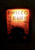
It requires an Eveready 746 (4.5v) A battery and an Eveready 467 (67.5v) B battery. I was able to locate an old 746 so I could scan it and make a new label. The bonus is that I get the small/large pin connector that goes with the battery.
I'm attaching the raw scan pdf of the label. If anyone wants to take a stab at cleaning it up please feel free to do it. That's not something I've attempted yet. Surprisingly the battery still has 3.9 volts although that’s with no load.
I've got the recap done, did not elect to restuff caps on this one so it went quickly. There was also a lot more room under the chassis compared to the Motorola 5A9M. I have some supplies coming for the battery remake so I started to look at restringing the dial. The schematic has the diagram so that's easy but I don't have a pointer. I was able to find some pictures of a pointer in a youTube restoration video by Troy Brokenshire. I 'think' I can make a pointer based on the images. I've got some think gauge steel sheet that should be good. The hard part will be getting the cutting and metal bending done on such a small little piece. I'm sure they were just punched out on a press in the factory.
Here's a picture from Troy's video and then my first paper trial. I have some more dimensions to figure out but I think I have the origami part of it figured out. I may have to get creative about ways to hook the dial string onto the pointer if I can't make the tiny cuts I'll need. Its going to take some trial and error I think. I have a piece of brass that will serve as the actual pointer and I will glue that to the pointer frame you see in the photo. There seem to be a number of examples of this radio on eBay in various states of disrepair so if all else fails, I should be able to find a donor or someone parting one out.
Bob;
I've made pointers before out of thin sheet metal from a various things, I think I made one for a Guild Spice Chest out of the steel cover from a junked home theater amp I picked up to scrounge the power transformer from. Tin snips, and a Dremel tool are very useful, as is a bench vise.
The plug on that battery looks familiar, I have a Canadian Marconi 260 portable that originally used a pair in the same style for the "A" batteries, which someone clipped off. Unfortunately the Marconi set is AC only at the moment, it used a tapped output transformer to accommodate the use of a 50B5 and a 3Q4, both the speaker, and the output transformer were replaced with a Hammond substitute, which is far too large.
Regards
Arran
Thanks Arran, that's the approach I took. My first metal prototype is seen here. It doesn't quite do the job as its hitting something as it travels along the dial face but with a few more iterations I'll have something that works. At the moment my dial string is slipping as well so I have some adjusting to do on that but all in all I think it will work out fine in the end.
I was able to get the homemade pointer to work and got the dial stringing together. After connecting up the A and B batteries however, I had absolute silence with the radio so there will be more trouble shooting on the horizon.
I took some voltage measurements and all the readings were nominal with the exceptions of the 1S5 pin 4 at 0v instead of 12v and the 3S4 Pin 3 grid at -6v instead of -1.3v.
The 3.3Meg, 470k, and 1.5Meg resisters were all in spec and the #18 .01uF and 0.005 uF caps were replaced. The 820 ohm resistor was high at 1.2k so I'll change that out would not think that's the problem.
(also.. 0.2v of audio signal on the grid of the 3S4 yielded no sound)
My next step is to check my recapping to be sure all are connected correctly and nothing is missing.
It is strange that the screen has 0V. I thought that a 3 megohm resistor from B+ to screen was very high but other sets using this tube combination are similar wired. I don't know if 0.2V is enough to drive the output tube; I think that you need more like 1-3V to drive it. I wonder if your output tube is dead and if the 1st audio is seriously gassed or has a screen to suppressor short. Yes, it may not be common to have more than one failure, but The set may have been in storage for a long time. Pull the 1st audio tube and measure the plate and screen pins. They should go very high with a DVM. If measuring with a traditional passive VOM, the voltage at the 1S5 screen may be artificially low. The RCA BP10 schematic states to measure with the RCA Voltohmyst or Channelyst, which, I believe were VTVMs.
"Do Justly, love Mercy and walk humbly with your God"- Micah 6:8
"Let us begin to do good"- St. Francis
Finally able to get back to this radio. I worked through the circuit and did not see any mis-wiring issues. I rechecked voltage readings and all were the same except pin 4 on 1S5. It now was at 15 or 16 v instead of 0. Its most likely I simply measured incorrectly (perhaps wrong pin) last time since I did not really change anything. In any event the radio was still dead silent so I decided to check the speaker. It did not show an open voice coil and the transformer ohmed out OK. I put 1.5v across the voice coil by intermittently touching a lead to it...nothing. That seemed strange, I should at least hear some static since its a PM speaker. I figured, what the heck and moved to a 9v battery and a quick tap on the voice coil. I heard a loud pop...darn, did I just fry the voice coil? I went back to the 1.5v battery and lo and behold now I'm getting the static and clicking I expected. I think at the end of the day I simply had a stuck voice coil and the 9v jolt freed it up. Playing like a champ now. First thing I picked up was talk radio but then I got the Phillies vs Mariners...being a Philly phan on the west coast it was a real treat!
I'd rather be lucky than good was the old saying. You worked hard on this little guy so I would say you were good and lucky. I love baseball on radio. Paul
Interesting issue. Is the voice coil rubbing on the magnet pole? If so, music will sound rather bad. Do check the voice coil flexible leads. They may be broken and intermittent, although at 0.1 - 0.2 Watt output, I don't expect much flexing of these leads from earthshaking bass and large movement of the voice coil and cone.
"Do Justly, love Mercy and walk humbly with your God"- Micah 6:8
"Let us begin to do good"- St. Francis
I've played music as well and it sounds OK as does voice. Its possible it was something other than the voice coil but I can't think of what that might have been. Like most of the radios I work on they only actually get played once in a long while. Thanks for the advice and comments, you guys always help me get through these radios! I truly enjoy the resurection of these vintage pieces. Its the challenge of making them look better than they are when I find them and getting them back to playing condition if possible. I learn new things and like the problem solving. Once done, I've kept a few, sold a few, given a number of them away to friends and charities. In this case my wife thought it was so cute she put it on her book case along with the advertisement.