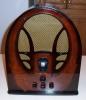
Hi, new user here from the Netherlands, who recently got a Philco-Tropic model 48-828 to repair.
major issue is the "burned" 32-8189M output transformer, which does give me the following questions.
-the schematic shows a push pull AF amplifier stage with 2 7B5E tubes, that some how work without a separate phase shifting tube .. ? I expect the output transformer pay a roll in the push pull concept
-where can I get a replacement transformer or a 32-8189 ? I can buy a universal push pull transformer (%W) for company like Hammond, but will it work looking an my other question??
Thanks
(This post was last modified: 12-09-2025, 05:54 AM by vckrijt.)
From what I understand most of the post war Philco Tropic sets were either manufactured in Canada, or in Great Britain, without seeing the set from the back it's hard to tell which. I think it's likely that this was a British made Philco as the knobs are different from any I have seen on U.S or Canadian sets, this is assuming that the knobs are original.
With regard to the power output stage, a lot of Philco sets used a "screen grid inversion" setup so they could eliminate using a phase invertor/splitter tube, I've never seen this in a set with 7B5s but not reason it could not be done. A 7B5 is basically a 6K6GT or a #41 with a loctal base so an output transformer that will work with those should work with a 7B5.
Regards
Arran
thanks Arran, I will chatgpt on "screen grid inversion" and try to post a inside back picture (I see no add picture function n this quick reply field ..?
BR Victor
Just a thought, you may be able to adapt a push pull output transformer from a scrapped European radio like a Phillips, that uses push pull power pentodes. It would have to be something close in plate load impedance to a 6K6GT, maybe some other power pentode like an EL95, but I would have a look through the tube/valve specs, most of which are posted online.
Regards
Arran
thanks for the thought Arran, what I noticed on the Philco transformers in this push pull (Philco screen grid phase conversion concept) that the centre tab primair is not symmetrical (ohm values differ a little 205/240) how does it matter for a other output transformer ??! Gr Victor
vckrijt Wrote: ... the centre tab primair is not symmetrical (ohm values differ a little 205/240) ...
What is critical in a transformer winding is the number of turns. The farther away from the core the more wire is required per turn. A tapped winding can have the same number of windings per section but different resistances per section.
In the Philco Library, under "Service Info" you can find a schematic and service information on this specific radio. It is in the Philco 1948-1949 Home Radio Year Book document.
Courage will follow when Faith takes the lead.
(This post was last modified: 12-13-2025, 08:52 PM by Joe Rossi.
Edit Reason: admin: link added to Joe's post
)
I think that the schematic is just giving a literal DC resistance measurement value for the output transformer primary, such as one half of the primary is would on top of the other in a different layer. I haven't heard of any issues regarding replacing an audio output transformer in any sets with the screen grid inversion setup, they just used a replacement that matched what the tube types required. In terms of why it failed it could be corrosion, or it could be that the set was played with leaky coupling capacitors, C-206 being leaky could also cause a failure.
Regards
Arran
Victor, you don't have to get the transformer from Amplified Parts but I'm sure there's an online source in Europe saving you big bucks in shipping and tariff. The one from AP is the one to copy. Or, you could find a junker chassis with 2-6K6 output tubes. That output transformer would work just fine.