Posts: 257
Threads: 39
Joined: Jul 2016
City: Spring Lake MI
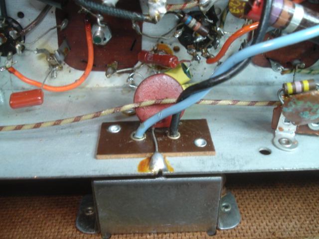
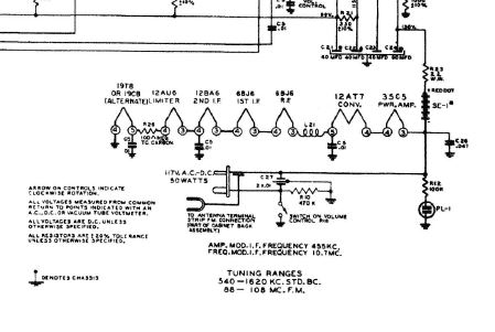
This cap is labeled 2X.01. It is C27 on the schematic Duel Ceramic .01 - .01 It has three leads one to each side of the line and one to ground.
It is bad, one side is shorted to ground not sure if this is an "X" or 2 Ys, what should it be replaced with.
Thanks
This radio is a Zenith H725 not H724, sorry.
Jim
Spring Lake MI
(This post was last modified: 01-08-2026, 08:06 PM by Jimradio.)
Posts: 18,427
Threads: 622
Joined: Oct 2011
City: Jackson
State, Province, Country: NJ
Since this goes to the chassis, this should be two Y-caps (safety caps Y-rated), 10nF each.
https://www.mouser.com/ProductDetail/Mur...EBWA%3D%3D
People who do not drink, do not smoke, do not eat red meat will one day feel really stupid lying there and dying from nothing.
Posts: 257
Threads: 39
Joined: Jul 2016
City: Spring Lake MI
Thank you so much morzh.
Jim
Spring Lake MI
Posts: 18,427
Threads: 622
Joined: Oct 2011
City: Jackson
State, Province, Country: NJ
Your radio and the one I've just finished, 7H920, are nearly the same.
Mine has no cap across the AC line.
I am not sure you need it either.
Actually, when I found H724 on Riders, it shows exact same tubes as in mine.
Yours has two 6V tubes, hence a series resistor in the filaments tring.
Which one do you actually have?
Is it 724Z?
People who do not drink, do not smoke, do not eat red meat will one day feel really stupid lying there and dying from nothing.
Posts: 257
Threads: 39
Joined: Jul 2016
City: Spring Lake MI
Sorry I did a typo in the title of my radio it is an H725....I can't find an exact schematic for mine. Mine has a 35C5, 19T8, 12AU6, 12BA6, 12BA6, 12AT7 and 6BJ6 the closest schematic is the CH7G01Z1 but it shows two 6BJ6.
Radio Museum shows a H725Z1 mine is Green. My chassis is stamped H725, the label on the bottom of the radio is gone.
The schematic shows a 470K resistor from switch to ground? I put a polarized cord on the chassis with neutral direct to chassis or ground, the hot side goes through the switch then to B+. Also replaced the selenium rectifier with a 4004 diode and a 75 ohm 5 watt resistor B+ is 133v schematic shows 130v. I eliminated the 470K resistor.
Jim
Spring Lake MI
Posts: 257
Threads: 39
Joined: Jul 2016
City: Spring Lake MI
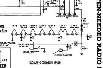
This a Beitman schematic of this location, no C27 cap or 470K resistor.
Jim
Spring Lake MI
Posts: 18,427
Threads: 622
Joined: Oct 2011
City: Jackson
State, Province, Country: NJ
>The schematic shows a 470K resistor from switch to ground? I put a polarized cord on the chassis with neutral direct to chassis or ground, the hot side goes through the switch then to B+. Also replaced the selenium rectifier with a 4004 diode and a 75 ohm 5 watt resistor B+ is 133v schematic shows 130v. I eliminated the 470K resistor.
I explained it on ARF about 470K.
The way it is shown, it is a bleeder.
People who do not drink, do not smoke, do not eat red meat will one day feel really stupid lying there and dying from nothing.
Posts: 1,420
Threads: 41
Joined: Jan 2014
City: Wellborn Florida
Jim look at this has a 35B5 not a 35C5 but is a H725. David
Posts: 18,427
Threads: 622
Joined: Oct 2011
City: Jackson
State, Province, Country: NJ
I guess there are variations.
My radio has undeclared resistors to GND on the SG of both 12BA6.
People who do not drink, do not smoke, do not eat red meat will one day feel really stupid lying there and dying from nothing.
Posts: 257
Threads: 39
Joined: Jul 2016
City: Spring Lake MI
Here is another schematic showing two 6BJ6, my radio has only one in the RF position.
Jim
Spring Lake MI
Posts: 257
Threads: 39
Joined: Jul 2016
City: Spring Lake MI
Here is the tube layout with the 6JB6 in the RF position.
Jim
Spring Lake MI
Posts: 257
Threads: 39
Joined: Jul 2016
City: Spring Lake MI
Thanks for all your help. I will change C26 to a X .047 B+ to chassis or ground. I ordered some Y .01 to put on the power leads not too sure if it needs them.
Jim
Spring Lake MI
Posts: 3,188
Threads: 226
Joined: May 2008
City: Omak
State, Province, Country: WA
Hello Jim,
Here is the safety capacitors that I use made by Vishay .
https://www.mouser.com/ProductDetail/Vis...l4eQ%3D%3D
• X1, Y2 according to IEC 60384-14
• Line-to-line filtering (Class X)
• Line-to-ground filtering (Class Y)
• Primary and secondary coupling (SMPS)
• EMI / RFI suppression and filtering
Sincerely Richard
Posts: 2,327
Threads: 23
Joined: Jul 2020
City: Greenlawn
State, Province, Country: NY
Hi folks,
Do be careful, this, and most other of these AM FM sets are not a warm chassis sets; they are HOT chassis sets. And doubly dangerous because the line to the chassis is what is switched. I think that there is only 1 cap, and it is between hot and chassis.
"Do Justly, love Mercy and walk humbly with your God"- Micah 6:8
"Let us begin to do good"- St. Francis
Best Regards,
MrFixr55
Posts: 3,188
Threads: 226
Joined: May 2008
City: Omak
State, Province, Country: WA
Hello MrFixr55,
Well Said I always use a isolation transformer when working on sets like this .
Sincerely Richard
Users browsing this thread: 2 Guest(s)
|
|
Recent Posts
|
|
Plug Voltages Needed For A 1943 CRV-20130 Power Supply
|
| hello david,
I have a similar generator in my collection that features a cast iron, single-cylinder Briggs & Stratt...radiorich — 01:00 AM |
|
under chassis parts locator diagram for 1938 Zenith 9s262
|
| Has anyone gone to the trouble of creating an under chassis parts locator image? Yes, I can identify components by foll...bobloney — 08:57 PM |
|
Plug Voltages Needed For A 1943 CRV-20130 Power Supply
|
| Try looking at this site the book mark is for a old generator that I was given. David https://radionerds.com/index.ph...David — 08:36 PM |
|
Plug Voltages Needed For A 1943 CRV-20130 Power Supply
|
| Hello Everyone,
I am looking for voltage identification for all the pin positions on the socket of a CRV-20130 power su...Tonym4704 — 08:16 PM |
|
Philco P45-6365 Universal Transformer Instruction Manual
|
| Can anyone guide me to where this may be found?GRG — 03:00 PM |
|
54C Complete Teardown/Rebuild
|
| I don't think that I have encountered a 12Z3 before, curious how it uses one of those but includes a #43, which is a 25 ...Arran — 02:17 PM |
|
HiFi (Chifi) tube amp build - but my own design.
|
| It's the other forum. I'm also in DIY, but mostly read there. Honestly, I kinda jumped into this without much thought to...TV MAN — 10:43 AM |
|
Philco 71 Code 125
|
| Hello,
I am in need of a schematic for this radio. Mine has the three separate circular tube shields and a shadow me...dconant — 08:06 AM |
|
Stromberg Carlson 1500 Squeal
|
| And life just keeps getting more complicated.dconant — 07:57 AM |
|
54C Complete Teardown/Rebuild
|
| Hello Roy,
here is this one
sincerely Richardradiorich — 12:45 AM |
|
Who's Online
|
| There are currently no members online. |

|
 
|