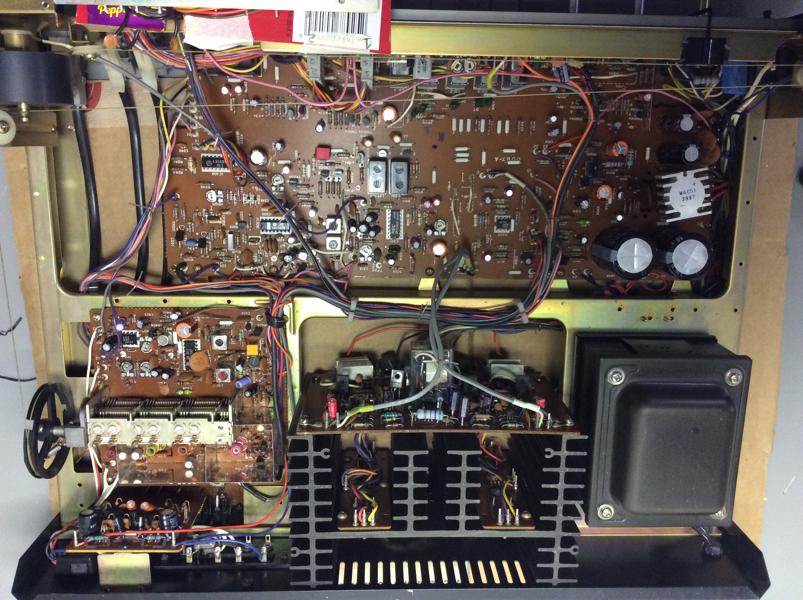
Hello Guys,
I am currently restoring a Realistic model STA-240 Receiver for a friend of mine.
Its two main filter capacitors were low in value and had leakage.
So, I pulled a few more Electrolytics and decided to make list of ones to order.
So, between cold solder joints and scratch controls I started replacing the capacitors so far, I replaced about 30 and I decided to stop while my luck was good there about a dozen of the original ones in the whole set like 6 of them are on the Phono preamp board.
A little side note is this unit was built by Matsushita for radio shahack and was only built for one year 99 % of the electroytics were Chem-Con .
Anyway Here is some photos of my handy work and you will see a few spots where traces lofted and I had to do some minor repairs .
The one thing I dread is to clean all the controls and switches I already did the speaker relay .
Sincerely Richard
Hello guys,
I wish I would took photos of before the chassis was covered in 1/8 of pure dust ,
Far as the two main filter capacitors the original ones were rated at 8000ufd at 50 volts .
I bought two Nichicon rated at 8200ufd at 50 volts I wanted to get some better ones but 30 mm diameter was limit since they were so close because when I tested the new ones in place with the set at idle the B-plus and B-minus rails measured like 47 volts DC .
One thing I wish I could find is a schematic but being offered one year makes it tough .
Sincerely Richard
P.S. this set lives in a workshop !
Nice work. I like how the original wiring is neatly laid out and attached and soldered to the posts. I could never do that. Must have been done by machine?
Hello guys,
I’ve finished replacing all the electrolytic capacitors, cleaning the switches and other controls, and even gave the tuning capacitor a bit of attention. Altogether, I replaced 68 capacitors. This weekend, I’ll wrap it up, record a video, and upload it to show it working.
I was looking for that repaired traces, eventually found them. Yea, one-sided board and, likely, the vias are not plated. Makes it easy to lift traces.
From the reflection of the light from the soldermask I cannot see if the flux residue has been cleaned off; in case rosin is still there, I recommend removing it (IPA works nice and is sold much cheaper than all those flux strippers in pressurized cans), because it is corrosive to copper and eventually results in that green.
PS. I bought a full recap kit for my Philips CD880, but never recapped it. I put the caps in my LCR meter and realized they are all good with no degradation whatsoever, so I chose to keep the originals for now.
People who do not drink, do not smoke, do not eat red meat will one day feel really stupid lying there and dying from nothing.
I know, they neglected cleaning rosin off. I guess, soldermask shielded it some, but once we touch it and the soldermask gets damaged, this is where it really gets corrosive.
I've seen rosin sipping in a rocker switch of one of our devices and getting the innards green after a few years to the point of the switch stop getting made. I opened it to investigate and this was what I found.
People who do not drink, do not smoke, do not eat red meat will one day feel really stupid lying there and dying from nothing.
Hello guys,
my main question is about the two original main electrolytic capacitors, which were 8000 µF at 50 volts, and I replaced them with 8200 µF at 50 volts. I measured the positive and negative voltages, and they are both ±46.00 DC volts, which leaves only a 4-volt DC margin. The biggest issue was the space between the two capacitors on the main circuit board—I could have gone bigger, but there was no room.