Posts: 24
Threads: 3
Joined: Nov 2017
City: Bloomington
State, Province, Country: Indiana
Just finished rewiring dial lamp, it now works. Replaced dial string. Works better. Replaced resistor 23 and 24 with correct ones with 2 watts. Taped and numbered all wires coming from power transformer and removed it from chassis. That was quite challenging, but kinda fun. Wires were totally crumbling even inside transformer. I put heat shrinking tubing on each wire and renumbered them. Tomorrow I plan on reinstalling the transformer and replacing the rest of crumbling wires. Then I’ll bring it up slowly and see if it plays and rewards me for all my time consuming work. Thanks again for all your help. Hope the blizzard moves out quickly.
Jeff
Posts: 24
Threads: 3
Joined: Nov 2017
City: Bloomington
State, Province, Country: Indiana
OK, so I’ve replaced all cracked wire especially from the power transformer. Rebuilt pilot light, and now it works. Replaced dial string. I now have a slight buzzing sound only. There was a small wire broken on the coil in the back of set. I tried to find out where and connected to nearest protruding wire, but it did not affect the reception. All voltages on electrolytics where good. I’m making progress, but seems that antennae is it functioning.
Posts: 18,427
Threads: 622
Joined: Oct 2011
City: Jackson
State, Province, Country: NJ
That one I think might be the antenna coil. Makes sense to see if you soldered it to where it should be.
People who do not drink, do not smoke, do not eat red meat will one day feel really stupid lying there and dying from nothing.
Posts: 24
Threads: 3
Joined: Nov 2017
City: Bloomington
State, Province, Country: Indiana
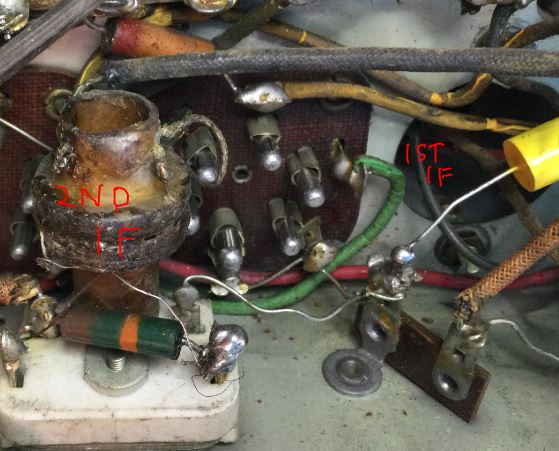
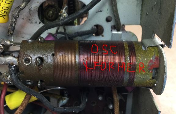
I do think it’s the antenna coil. Now that the audio is working. Here’s some pics.
Posts: 18,427
Threads: 622
Joined: Oct 2011
City: Jackson
State, Province, Country: NJ
Well, the 1st one I think is the 2nd IF coil and the second photo is the oscillator coil.
People who do not drink, do not smoke, do not eat red meat will one day feel really stupid lying there and dying from nothing.
Posts: 24
Threads: 3
Joined: Nov 2017
City: Bloomington
State, Province, Country: Indiana
in the 1st pic…..
When I attach the small wire (coming off the green side of the resistor) to the connection right above, I get some serious motor boating. It’s not the sound I want, but it’s something.
Posts: 18,427
Threads: 622
Joined: Oct 2011
City: Jackson
State, Province, Country: NJ
You need to figure the coil out. And do use schematic when you solder wires.
People who do not drink, do not smoke, do not eat red meat will one day feel really stupid lying there and dying from nothing.
Posts: 2,327
Threads: 23
Joined: Jul 2020
City: Greenlawn
State, Province, Country: NY
Hi Jeff,
Refer to the pictorial and the parts list for the radio, found in our Philco Library, a link posted here:
https://philcoradio.com/library/download...20Book.pdf
Below are snags of your 2 pics. I identified the transformers based on the pictorial in the above service document:
The exposed coil in the pic below is the 2nd IF transformer. The one in the can is the 1st IF transformer:
The coil in the pic below is the oscillator transformer:
The following tests may help you. Do use the RCA Receiving Tube Manual for the pinouts (Tube socket wiring) for the 75, 78 and 6A7 tubes as your problem now lies in these stages. The diagram below has been modified to show most of the connections for the 39-7 and eliminate the connections for the 39-6. Ensure that your work is true to the diagram other than you can leave the pushbuttons out of the circuit and connect tuning cap 3 (A and B) per the diagram.
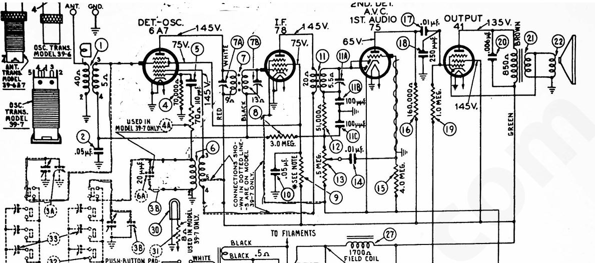
Start out by disconnecting power and set your DVM to Ohms, auto ranging. - Measure between the diode plates (Pins 3 and 4 tied together) of the 75 Detector / 1st AF amp and the junction of the secondary of the 2nd IF transformer #11 and 51 KOhm Resistor #12, across 1Trimmer cap 11A. You should read about 5 Ohm. This validates the secondary of the second IF transformer.
- Next, measure between the plate (#Pin 2) of the 78 IF transformer and the 6A7 Mixer Plate (Pin 2). You should get a reading close to 15 ohms. This confirms connection from the 78 Plate, through the 2nd IF primary, Pins 4 and 5 of the Oscillator coil, the 1st IF Primary and the Plate of the 6A7 Convertor.
- Next, measure between the Plate (pin 2) of the 6A7 and the "Grid Plate" (Oscillator Plate, Pin 4) of the 6A7 Convertor tube. There should be about 6 Ohm. This again confirms the 1st IF transformer primary abd confirms the continuity of the Oscillator Coil between pins 3 and 5.
- Next, measure between chassis ground and the stator of the oscillator section of the tuning cap (usually the section closest to the front of the tuning cap and the shaft. There should be a reading of somewhere between 5 and 40 Ohms (resistance is not on the diagram). This confirms continuity of the coil and connection to the oscillator section of the tuning cap.
- Next, measure between the grid cap of the 6A7 and the grid cap of the 78 IF tube. This confirms continuity of the secondary of the antenna coiland the secondary of the 1st IF transformer. Resistance reading should be about 18 Ohms. Next measure between the RF stator of the tuning capacitor (the rear section; the grid cap of the 6A7 connects to it and the grid cap of the 78 IF tube. This confirms connection to the tuning cap.
- Next, verify continuity between the frame of the tuning cap and the rotor of the tuning cap and between the frame of the tuning cap and chassis ground. These readings should be Zero Ohms.
- Next, verify continuity between the antenna and ground connections. This should be about 40 Ohms.
- Finally, verify that you replaced the 0.05uF cap between chassis ground, pin 4 of the Antenna transformer and the 1st IF secondary (this is the AVC Line)
Correct any defects found, and you will likely restore operation of the radio.
Good luck!
"Do Justly, love Mercy and walk humbly with your God"- Micah 6:8
"Let us begin to do good"- St. Francis
Best Regards,
MrFixr55
Posts: 24
Threads: 3
Joined: Nov 2017
City: Bloomington
State, Province, Country: Indiana
OK thanks, I’ll try and follow your instructions
Posts: 2,327
Threads: 23
Joined: Jul 2020
City: Greenlawn
State, Province, Country: NY
Hi Jeff,
Sorry for the long drawn out instructions, but just take it one step at a time. I think that you will find the issue using this procedure.
Good luck.
"Do Justly, love Mercy and walk humbly with your God"- Micah 6:8
"Let us begin to do good"- St. Francis
Best Regards,
MrFixr55
Posts: 24
Threads: 3
Joined: Nov 2017
City: Bloomington
State, Province, Country: Indiana
well, I started at the top and was getting good reading or close. Then I got to your 5th point checking grid cap o 6A7 and 78. Got no resistance. and the rest of it. Nothing. 6 was OK. but 7 point was a no show also. There is only one wire coming out of the back, which I assume is the antenna. Shouldn’t there be a ground wire also. if so where would it connect in chassis. Schematic doesn’t show.
I rechecked all of your points a 2nd time and everything checked out the same.
Posts: 18,427
Threads: 622
Joined: Oct 2011
City: Jackson
State, Province, Country: NJ
Then try tthe Grid cap of 6A7 to the Cap #2 (in the sch it is the top one) OR Resistor #8 (3 Megohm, the lefmost pin in the sch).
Then from the same Cap or Resistor pin measure to the 78 grid cap.
This will tell you which one is open.
People who do not drink, do not smoke, do not eat red meat will one day feel really stupid lying there and dying from nothing.
Posts: 24
Threads: 3
Joined: Nov 2017
City: Bloomington
State, Province, Country: Indiana
So with grid cap not on 6A7 tube I get 5.5 ohms on Cap #2.
On Resistor #8, I get 611k ohms.
with the grid cap on the tube 6a7 I get 8 ohms on cap 2 and 611k on Res. 8.
Posts: 18,427
Threads: 622
Joined: Oct 2011
City: Jackson
State, Province, Country: NJ
Jeff,
OK, I will ask again, as, short of your wire connecting cap #2 to resistor #8 being open, what you are saying is impossible.
Find the point where the two are connected.
Then:
1. Measure to the Grid Cap of the 6A7 (and BTW what does "So with grid cap not on 6A7 tube" mean? If NOT on the grid cap of 6A7, what is it on then?)
2. From the same point (the resistor and the cap connected) measure to the Grid Cap of the 78.
If however the Resistor and cap are NOT connected (remember, each has two wires so there are 4 possible combinations; if the wire connecting them is not strikingly obvious, try all for combinations, see if at least two pins are connected and then use THAT point as the point to measure to both grid caps). It is possible you are measuring from the wrong Res #8 pin.
People who do not drink, do not smoke, do not eat red meat will one day feel really stupid lying there and dying from nothing.
Posts: 24
Threads: 3
Joined: Nov 2017
City: Bloomington
State, Province, Country: Indiana
OK, I found where the cap. and res. we’re connected. I connected that point to 6a7 and got no reading at all. I then connected It to 78 and got 13 0hms.
Users browsing this thread: 1 Guest(s)
|
|
Recent Posts
|
|
Stromberg Carlson 1500 Squeal
|
| And life just keeps getting more complicated. By dconant.
Dittos'Jimradio — 08:01 AM |
|
Plug Voltages Needed For A 1943 CRV-20130 Power Supply
|
| That looks a lot like an aircraft connector of some kind, even if it's a U.S.N power supply. I have a book somewhere abo...Arran — 02:56 AM |
|
Plug Voltages Needed For A 1943 CRV-20130 Power Supply
|
| hello david,
I have a similar generator in my collection that features a cast iron, single-cylinder Briggs & Stratt...radiorich — 01:00 AM |
|
under chassis parts locator diagram for 1938 Zenith 9s262
|
| Has anyone gone to the trouble of creating an under chassis parts locator image? Yes, I can identify components by foll...bobloney — 08:57 PM |
|
Plug Voltages Needed For A 1943 CRV-20130 Power Supply
|
| Try looking at this site the book mark is for a old generator that I was given. David https://radionerds.com/index.ph...David — 08:36 PM |
|
Plug Voltages Needed For A 1943 CRV-20130 Power Supply
|
| Hello Everyone,
I am looking for voltage identification for all the pin positions on the socket of a CRV-20130 power su...Tonym4704 — 08:16 PM |
|
Philco P45-6365 Universal Transformer Instruction Manual
|
| Can anyone guide me to where this may be found?GRG — 03:00 PM |
|
54C Complete Teardown/Rebuild
|
| I don't think that I have encountered a 12Z3 before, curious how it uses one of those but includes a #43, which is a 25 ...Arran — 02:17 PM |
|
HiFi (Chifi) tube amp build - but my own design.
|
| It's the other forum. I'm also in DIY, but mostly read there. Honestly, I kinda jumped into this without much thought to...TV MAN — 10:43 AM |
|
Philco 71 Code 125
|
| Hello,
I am in need of a schematic for this radio. Mine has the three separate circular tube shields and a shadow me...dconant — 08:06 AM |
|
Who's Online
|
There are currently 1795 online users. [Complete List]
» 1 Member(s) | 1794 Guest(s)
|
|
|

|
 
|








