RCA 6K3 Preliminary Capacitor/Resistor Research
Posts: 172
Threads: 10
Joined: Mar 2026
City: Franklin
State, Province, Country: Maine
I'm working on getting together an order for replacement capacitors for the RCA 6K3 I picked up a few weeks ago and I have some questions. In a couple cases, I'm finding the part list and schematic either lacking clarity on the difference between two parts, or differing entirely from what is actually present in the radio.
The parts in question are:
C15 and C19: both are listed as 0.1 mfd, but in a part list for another device that uses these same parts by number (11414 and 4841 respectively), the C19 is explicitly listed as 200V. I presume the voltage is the difference between these? Voltage is only listed on a couple caps, and in those cases, it is 200V, otherwise it is not listed at all. Since most of what I'm ordering is 630V, I'm reasonably certain I'm good to just use the same replacement part in either case. Agree?
C24: one of three 0.01mfd caps, this appears to have a metal shield around it which is screwed to the chassis - I doubt it is available in a shielded form as a new replacement part. If I can evacuate the old shield and the replacement part fits inside, would I be okay to reuse it or should I try to fabricate something new?
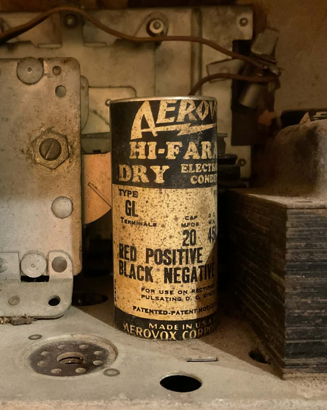
C16, C30, and C31: the electrolytics - the schematic and parts list specify 10, 10, and 18 mfd respectively, but all three bear different part numbers and further, in the chassis, they are all three the same 20 mfd 450V cans from Aerovox, at least according to the label. Should I replace what is actually there with the same values already present or is it better to adhere to the schematic where possible?
I have tested all of the resistors I can access in-circuit, which I know can throw off the readings, but most of them tested to 10% variance or less. There are three that I plan to replace, but I had a surprising result in one section of the voltage dividing resistor. Every section tested well except one, R15, which is supposed to be 13K ohms, but when first connected shoots up to around 1M and then over a minute or two of sustained contact dropped to 530K. I'm guessing this is related to this piece being tested in-circuit? Or would this suggest something wrong in this piece?
The only resistors I was unable to test were the ones inside the transformers. The cans around these appear to be riveted on so I don't think I'm going to go down that route unless I find something amiss later on.
On what is probably an unimportant note, there is a capacitor on the part list, C33, 0.015 mfd, that I can't find anywhere in the diagram, ,schematic, or chassis. It is not part, nor is it indicated as are other components for the circuit for the magic eye tuning tube included on the two other models that share this same basic chassis. Possibly an error that it is included? These documents seem to be fallible.
Thanks in advance for guidance on these components.
Best wishes,
Roy
Posts: 18,427
Threads: 622
Joined: Oct 2011
City: Jackson
State, Province, Country: NJ
630V is good across the parts.
Why would you need to replace a shield which is a piece of sheet metal? Find a cap that fits inside.
Find the cap that is right against the rectifier tube output (C50). This value should be observed. The other two, which usually are after some sort of filtering choke or a resistor, could be increased. This said, it is always best to follow the original values.
Your R15 is likely bad. In or out of circuit.
C33 - what you can't find won't hurt you. Deal with what you see.
People who do not drink, do not smoke, do not eat red meat will one day feel really stupid lying there and dying from nothing.
Posts: 172
Threads: 10
Joined: Mar 2026
City: Franklin
State, Province, Country: Maine
Mike,
Thanks for the verification of 630V.
Re: the shield, I don't want to replace the shield if I don't have to, just wasn't sure if there was some electrical/electronic property of the shield or the capacitor inside it that would necessitate replacement. The replacements I've been ordering should fit inside, I think.
Re: electrolytic values, C30 (10 mfd according to documents) is the one that connects to the rectifier. I'm attaching a photo of the part that is installed. It's definitely old, but I'm not sure if it's original. Obviously, if the radio was serviced and parts were replaced, they could have been replaced with different values than original or designed. When you say that this value should be observed, would your recommendation then be to go with the value prescribed in the schematic vs what is in place? I have no desire to replace with something that is out-of-spec, on any of the three, let alone the one connected to the rectifier.
Best wishes,
Roy
Posts: 2,327
Threads: 23
Joined: Jul 2020
City: Greenlawn
State, Province, Country: NY
Hi Glyphmon,
+1 on what Morzh said. For non-electrolytic capacitors, the modern mylar capacitors rated 630VDC are best. For these caps, the higher the voltage the better.
The original caps may have been rate 200V because the old paper / foil / wax caps were much larger at higher voltages. Mylar or polypropylene dielectric is much more efficient, hence, these caps are smaller.
RE C24, yes, if you can hollow out the shield that the existing cap is in, certainly do so and install the new cap in that "can". This is the audio input cap. It is possible that it was shielded because of its physical location, but this was not common.
For electrolytics, it is different, at least it used to be. These were rated in "working volts". A 20 uF 450WV electrolytic would not achieve 20uF at 150V. With modern electrolytics, this may have changed.
It is best to replace the electrolytics with capacity values close to spec. However, the electrolytics back then had a tolerance (the level of accuracy) between -20% and +50% so a little more wasn't bad. However, for the capacitor closes to the cathode of the rectifier should not be too high. 20uf is not bad. I suspect that these caps have been replaced already as electrolytic caps do fail.
When you test a resistor in circuit, devices that parallel the resistor or in series-parallel with the resistor can affect readings. However, they often cause a lower reading than the actual resistance. I suspect that the resistor in question is open (burned out), as the resistors in series with it read correctly.
R5 and R7 can be tested easily. To do so:
"Open" the link between Terminals 1 and 2 on the back of the set. This terminal board is marked "Phono"
Locate Pin 5, "P1" of the 6H6 and connect one probe there. Connect the other probe to Pin 1 of the Phono terminal board. You shoud see a reading that is a sum of the value of R5 and the resistance of the IF transformer secondary. Since the secondary is only about 15 Ohm, then the received reading accurately reflects the reading for R5, 56,000 Ohms. If open, then you need to remove, disassemble and verify coil and resistor continuity.
To check R7, check between Pins 1 and chassis ground or pin 3. The reading should about 220,000 Ohms
If you did not find C33 in the radio or on the schematic, I wouldn't worry about it. Unfortunately, you can't call their tech support department and ask about the error in the documentation. The person that designed the radio was likely dead as of 1990, and RCA itself is dead. In fact, when I work on one of the radios in my collection, I say a prayer for those who built it and used it. Thinking about the history and the lives of the people surrounding these vintage radios is for me a touching part of this hobby.
Hope this helps.
"Do Justly, love Mercy and walk humbly with your God"- Micah 6:8
"Let us begin to do good"- St. Francis
Best Regards,
MrFixr55
Posts: 5,653
Threads: 56
Joined: Sep 2008
City: Sandwick, BC, CA
The Aerovox can pictured is an older replacement, possibly from the 1940s, or early 50s, the original RCA caps would have been in bright aluminum cans, no label, and may have been wet electrolytics, or at least the input filter cap. Traditionally the value of the input filter cap should be as close to original as possible, within 20 % of what the schematic suggests, or a tube manual if you have one handy, but I'm not sure that this matters as much with model electrolytic caps.
Regards
Arran
(This post was last modified: 04-15-2026, 02:44 AM by Arran.)
Posts: 172
Threads: 10
Joined: Mar 2026
City: Franklin
State, Province, Country: Maine
MrFixr55, thanks for the confirmation on those points.
As for the potentially open resistor R15, since that is a segment of what appears to be one large single component, what would be the way to repair this? Does the entire voltage dividing resistor need replacing, or can the existing piece be modified/supplemented with an appropriate replacement?
I'll pull the chassis back out of the cabinet to check the readings on R5 and R7 as you described before placing an order. If the readings come back poor, is there any best practice for removing the shields around the transformer since they are riveted on?
Arran, thanks for confirming the existing electrolytics are not factory original. I will make sure to match the replacements with the values specified in the schematics.
Best wishes,
Roy
Posts: 5,653
Threads: 56
Joined: Sep 2008
City: Sandwick, BC, CA
Roy;
It was the common practice, in the past to replace sections of a tapped voltage divider resistor if one section was open, by bridging the failed section with a new resistor, but at the same time you had to make sure that the old section wouldn't repair itself leaving you with two resistors in parallel with a net lower resistance. Given the vintage of this set it was probably a type of candohm wire wound resistor which was riveted to the chassis for heat dissipation. Opinions vary on what to do with these, some replace them with chassis mounted Arcol resistors, others gut the resistance wire out of the Candohm and reuse the terminals with discrete resistors, the third option is to mount a terminal strip and use higher wattage resistors then the originals.
Regards
Arran
Posts: 18,427
Threads: 622
Joined: Oct 2011
City: Jackson
State, Province, Country: NJ
Generally speaking, in Philco sets, any cap that is not marked "Philco" is a replacement.
People who do not drink, do not smoke, do not eat red meat will one day feel really stupid lying there and dying from nothing.
Posts: 2,327
Threads: 23
Joined: Jul 2020
City: Greenlawn
State, Province, Country: NY
Hi Roy, Arran beat me to it and with really good info. How to proceed depends on whether you are trying to produce a museum quality piece where you hollowed out all the original caps and used the casings to hide the new caps (called "stuffing" caps) or if you only care about everything above the chassis to look vintage and the underside can look new. The resistor we are discussing, RCA P/N 11466is a "Candohm". This resistor based voltage divider supplies the various "B+" voltages and the bias voltages for the 1st AF and Output tubes. Note that chassis ground is not the most negative point in the power supply. The center tap of the HV section of the power supply is. Please note that the negative lead of the Caps C30 and C31 does NOT go to chassis ground, the negatives go to the center tap of the HV secondary of the transformer. The negative of C16 DOES go to chassis ground. BTW, as Arran stated, the Aerovox 20/20 uF cap shown in the picture is definitely a replacement. The Parts list shows 3 different P/Ns for the 3 electrolytic caps.
You can leave the cap mounted but cut the wires from the under-chassis connections and replace these with modern caps under the chassis.
In either case I would completely replace all resistors in this voltage divider. (R13 through R18). Granted, the section that blew dissipated the most heat and power as it had the highest resistance, however, it's like headlight bulbs in the car. If you have to replace one, you will be doing the other really soon.
I think that the easiest and most reliable way to replace these resistors is to remove the Candohm (Drill out the rivets), mount a terminal strip or 2 and use 10W ceramic resistors. Dress these so they get as much ventilation as possible and keep them as far away from other devices as possible. They can be placed against the chassis and allow the chassis to dissipate heat, especially if the voltage divider resistor was a metal enclosed resistor ("Candohm") mounted against the chassis. DO make sure that you connect the wires routing the resistor correctly. Alternatively, get the aluminum encased resistors that Arran referred to as "Arcol" resistors and mount them on the chassis, or on a metal plate that you then mount to the chassis.
"Do Justly, love Mercy and walk humbly with your God"- Micah 6:8
"Let us begin to do good"- St. Francis
Best Regards,
MrFixr55
Posts: 431
Threads: 9
Joined: Apr 2023
City: Roanoke
State, Province, Country: Virginia
glyphmon Wrote: Since most of what I'm ordering is 630V
In plastic caps I only buy 630 volt. Plastic caps don't care what the voltage is as long as it is below the rated voltage.
I do the same thing with 1 amp rectifiers in the 1N400x series. I only buy 1N4007 (1 kv) because they can be used in place of the lower voltage 1N400x rectifiers.
Note that I buy each value of plastic cap in a quantity of at least ten, and I buy 1N4007 100 at a time. I stock parts for a variety of electronic work.
Dale H. Cook, GR/HP/Tek Collector, Roanoke/Lynchburg, VA
https://plymouthcolony.net/starcity/radios/
Posts: 172
Threads: 10
Joined: Mar 2026
City: Franklin
State, Province, Country: Maine
MrFixr55, I'm going for functional and generally authentic external look. I'm not laboring over minor cosmetic alterations, but I am trying to keep the general construction and function/circuits authentic as well. So, I'm not going to replace an entire chassis with new radios, but as far as a piece like this candohm, whether it's a single unit or an assembly of individual resistors, I'm fine with the most expedient and reliable way.
Photo of the current part:
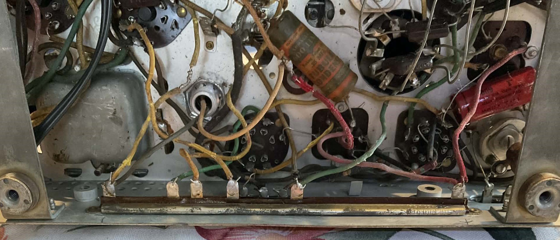
In your terminal strip scenario, you mention mounting them against the chassis - I take it you mean to solder them in place on the strip such that the bodies of the resistors can press against the chassis side without making electrical contact, like a heatsink? Is the spacing and length of the segments of importance to reproduce, or is it arbitrary and more about getting it to tie together correctly? Given that in testing the segments there were terminals in common, I presume that the resistors themselves must either have solder points in common, or a separate connection between them to connect the series. This is of course in addition to the other wires that come in from the other points in the chassis.
Separately, after following your guidance on testing R5 and R7 (I actually also checked at the base of the transformer directly as well since the R7 tested very weird at the exterior terminals), R5 tests at about 80.2K and R7 tests at 230K, so it sounds like R5 or something connected to it may be problematic. Any tips on extracting the transformer from the shield, or is it simply a matter of grinding off/drilling out the rivets?
Best wishes,
Roy
Posts: 172
Threads: 10
Joined: Mar 2026
City: Franklin
State, Province, Country: Maine
Not to reply to myself, but, I did find this guide from back in the day already as an attachment in this forum, though I don't know the context of the post:
https://philcoradio.com/phorum/attachment.php?aid=5868
This appears to be the identical candohm (from an RCA 6K2), or if not, the values it is supposed to have are the same. I know it has said to use 10 W resistors, but some of these values are really pushing the bounds of the 20% rule of thumb. I've been going with JustRadios.com, so if people would recommend a different source, I'm open to trying something else. I'm seeing a few other closer values in 5W. Both the 5W and 10W are advertised as +/- 5%. Would the following values be acceptable in this case (replacement value is closest 10W, with closer 5W values indicated in parentheses if available):
Orig -> Replacement
3.5K -> 4K (3.5K available in 5W)
13K -> 10K
85 -> 82
175 -> 200
40 -> 47 (40 available in 5W)
As far as how to install, I was thinking of getting a 13-terminal strip to be able to space things out, since heat is a concern and also I understand that 10W resistors are going to take up more space in the first place. Something like this from Tube Depot: https://www.tubedepot.com/products/termi...-terminals
Maybe not going the same exact route as in the guide but a similar premise. I like the dual terminals to keep the resistors and connecting wires separate.
Posts: 5,653
Threads: 56
Joined: Sep 2008
City: Sandwick, BC, CA
You can also buy resistors from Mouser and or Digikey as they have more selection then Just Radios, WJOE Radio has some as well but the selection is limited too. Generally you would want to at least double the Wattage rating on a resistor, especially power resistors, so if you think it will dissipate 5 Watts use a 10 Watt, or 3/4 of a Watt use 2 Watts. The way these Candohms were typically, but not always constructed is that they wound the resistive wire around a insulated form, and then (I think) crimped terminals on top of the wire at various points. In any event they were often custom made for a specific model, or a certain series of models, but off the shelf resistors are usually manufactured in EIA standardized values, so you may have to go to the next value over what the schematic suggests, or wire combinations of resistors, in series, or in parallel, to come up with the same value.
Regards
Arran
Posts: 172
Threads: 10
Joined: Mar 2026
City: Franklin
State, Province, Country: Maine
Okay, punting back to the forum here since TubeDepot.com is pretty unresponsive about my information request.
Anyone have a good source for long terminal strips? They list a 26-terminal strip on their site, but I wanted to know how long it was to make sure it would fit the space available in the chassis to recreate the function of the candohm. So far no answers over email or on the phone. I'd like to make it out of one piece rather than have to potentially put additional holes in the chassis to accommodate several different strips. I was surprised just how ginormous these 10W resistors are.
Best wishes,
Roy
Posts: 18,427
Threads: 622
Joined: Oct 2011
City: Jackson
State, Province, Country: NJ
You do not want a real long one unless it has fastening points in the middle. Otherwise they are thin and will snap at some point.
Had this problem in a Grundig. they used a real long one with just ends supported. Was snapped in the middle.
People who do not drink, do not smoke, do not eat red meat will one day feel really stupid lying there and dying from nothing.
Users browsing this thread: 1 Guest(s)
|
|
Recent Posts
|
|
under chassis parts locator diagram for 1938 Zenith 9s262
|
| Has anyone gone to the trouble of creating an under chassis parts locator image? Yes, I can identify components by foll...bobloney — 08:57 PM |
|
Plug Voltages Needed For A 1943 CRV-20130 Power Supply
|
| Try looking at this site the book mark is for a old generator that I was given. David https://radionerds.com/index.ph...David — 08:36 PM |
|
Plug Voltages Needed For A 1943 CRV-20130 Power Supply
|
| Hello Everyone,
I am looking for voltage identification for all the pin positions on the socket of a CRV-20130 power su...Tonym4704 — 08:16 PM |
|
Philco P45-6365 Universal Transformer Instruction Manual
|
| Can anyone guide me to where this may be found?GRG — 03:00 PM |
|
54C Complete Teardown/Rebuild
|
| I don't think that I have encountered a 12Z3 before, curious how it uses one of those but includes a #43, which is a 25 ...Arran — 02:17 PM |
|
HiFi (Chifi) tube amp build - but my own design.
|
| It's the other forum. I'm also in DIY, but mostly read there. Honestly, I kinda jumped into this without much thought to...TV MAN — 10:43 AM |
|
Philco 71 Code 125
|
| Hello,
I am in need of a schematic for this radio. Mine has the three separate circular tube shields and a shadow me...dconant — 08:06 AM |
|
Stromberg Carlson 1500 Squeal
|
| And life just keeps getting more complicated.dconant — 07:57 AM |
|
54C Complete Teardown/Rebuild
|
| Hello Roy,
here is this one
sincerely Richardradiorich — 12:45 AM |
|
54C Complete Teardown/Rebuild
|
| Richard,
Had grabbed it already but thank you just the same. I find myself wanting to find some way to block out the...glyphmon — 12:03 AM |
|
Who's Online
|
There are currently 1923 online users. [Complete List]
» 1 Member(s) | 1922 Guest(s)
|
|
|

|
 
|