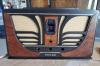
Sparton Junior Model 410 AC
Posts: 24
Threads: 5
Joined: Jan 2026
City: ENNISMORE
State, Province, Country: Ontario, Canada
Just acquired a very good looking Sparton Junior Model 410, TRF set.
I have restored the electronics and it is working fine, just need to do an alignment and repair the volume control.
Many of the tubes are original! It always ammazes me that vacuume tubes from 1930 are still still test very strong.
My problem is the dial cord (which looks like a fine brass cable) needs to be strung.
Does anyone have a dial cord stringing diagram for this radio?
Any tips or comments woud be greatly appreciated. Even a photo of a properly strung dial cord would be a big help.
gprutchick (Gary)
Posts: 18,427
Threads: 622
Joined: Oct 2011
City: Jackson
State, Province, Country: NJ
I have not found your Sparton model here but perhaps there are similar.
People who do not drink, do not smoke, do not eat red meat will one day feel really stupid lying there and dying from nothing.
Posts: 24
Threads: 5
Joined: Jan 2026
City: ENNISMORE
State, Province, Country: Ontario, Canada
Hi morzh
Thanks for the response.
I hame all of the Sams dial cord stringing guides and did not find anything close.
I will keep looking.
Perhaps someone that has this model could take a picture for me?
Posts: 5,654
Threads: 56
Joined: Sep 2008
City: Sandwick, BC, CA
It looks like the Pacific TV scan of the RCC manual does not show how the dial cable was routed either: https://pacifictv.ca/schematics/sparton410data.pdf
Bob Andersen worked on the U.S version of one of these maybe 15 or more years ago, he was hung up on the C-183 power output tubes which are more like a #45 but with 5 volt filaments, he ended up using 71As which work but are a lot more anemic, and do not accept plate voltages over 180 VDC. However there may be a viable sub in a peculiar variant of a 6V6 designed for series string TV sets, it's called a 5V6, I think that they were used as vertical output tubes or audio output tubes. The one drawback is that I don't think they were made in ST style envelopes, I think they were GT style, but they are beam power tubes so use beam forming plates rather then an extra grid. They also draw less filament current then a 183, 600 Ma verses 1.25 amps.
Regards
Arran
(This post was last modified: 05-08-2026, 01:45 AM by Arran.)
Posts: 24
Threads: 5
Joined: Jan 2026
City: ENNISMORE
State, Province, Country: Ontario, Canada
Hi Arran
I think I may have figured out the dial cord. In the process the very brittle plastic dial was cracked and broke into 3 pieces. Another set back!
The PP audio stage has original C-183 power output tubes, which are working great.
Changing the subject to the volume control. The volume control circuit of this radio appears to be modified. I believe the control was initially a 2-gand pot. The pot in this radio is a single gang but is very high in resistance. I opened it up and the resistive strip is basically open.
The radio appears to be modified. There is a 200 ohm fixed resistor installed on the first RF tube cathode to ground. The volume control is a single gang pot and had been wired to control the screen voltage of the first and second RF tubes. Also, there is no control on the antenna circuit as shown on the schematic. Do you know if this was a production modification? The original on/off switch is failed. It is a unique arrangement in that there is a cam on the rear of the volume control shaft that actuates an independent toggle switch. I have been trying to source a 2-gang potentiometer (50k & 30k) with an integral on/off switch. It would be ideal if I could find an original volume control. Or???
Posts: 2,327
Threads: 23
Joined: Jul 2020
City: Greenlawn
State, Province, Country: NY
Hi Arran,
Yes, I'm sure that they do not come on S or ST style, as a lot of series string TVs came about in the 1950s. I think that even post-war sets had GT style tubes ether than any pre-war or military surplus sets. I have not seen 5V6s but have seen 5AQ5s, which were quite popular in GE sets for Audio output, but deviate even more from the desired envelope.
Seems that according to Radiomuseum, these tubes were manufactured by or for "Sparton-Cardon", which has a rather interesting history. The company was named after William Sparks of the Sparks Withington Company (Sparton) and his 2 grandchildren, Carter and Donald. They produced tubes from 1924 to 1930, but did not obtain a license from RCA until about 1930, when they ceased manufacture and bought their tubes from RCA. According to Radiomuseum, the 183 was released in 1924 but the only sets that used the tube were 3 Sparton models between 1930 and 1931, making this an extremely rare tube if Radiomuseum is correct. It is strange that the tube was used in 1930 and 1931 but Sparton ceased actual production of tubes in 1930. Did they build a bunch of these before designing and building the radio or did they get RCA to knock off a run of these tubes when they speced the radio?? The 484s are another wierdo tube. They appear to be 27s but with 3V heaters instead of 2.5V heaters. Add this to the 3 section tuned circuit before the 1st RF amp tube, then all broad band, no tuned circuits between 1st RF and detector and this is a strange set to say the least! For those that have fixed or restored one, how do they compare to other TRF sets like a Philco 21?
I suppose that one way of dealing with this would be to either add a transformer with a 2.5V 3A secondary or add resistors on both sides of the filament to switch to '45s. Only problem is that the 45s were 1.5A at 2.5V so between the 2 tubes, you add 0.5A to the transformer load.
Here is a link to the same issue, from ARF. Solutions varied with one person recommending 2 45s with the filaments in series (that had to generate some hum for sure) to a statement that 71As were almost a match for power output.
https://antiqueradios.com/forums/viewtopic.php?t=286654
"Do Justly, love Mercy and walk humbly with your God"- Micah 6:8
"Let us begin to do good"- St. Francis
Best Regards,
MrFixr55
Posts: 1,797
Threads: 55
Joined: Feb 2015
City: Roseville, MN
Try Mark Oppat for the volume control.
moppat@comcast.net
Be specific in your request, ex. taper, shaft length and dia., flat end or splined. Put only the words "50k potentiometer" in the subject field.
If you don't get a response in about a week then try again.
Posts: 5,654
Threads: 56
Joined: Sep 2008
City: Sandwick, BC, CA
Mr Fix;
I looked up the specs on the C 183 tube in a 1937 Sylvania manual, and they were apparently manufacturing replacement tubes for Sparton and U.S Majestic sets around that time. The reason Sparton had their own tube manufacturing plant was so they could manufacture special tubes for their Equisonne series of sets that used a variation of the Jones Tecnodyne circuit, it was a means of royalty avoidance. What is interesting is that RCA and Sparton, according to the Douglas books, negotiated a cross licensing agreements as Sparton had patents that RCA wanted to use, and vice versa.
Regards
Arran
Posts: 5,654
Threads: 56
Joined: Sep 2008
City: Sandwick, BC, CA
I had a look at the schematic I linked to, I'm not sure why someone would play with the screen grid voltage on the RF amplifier tubes as there is no hint of this being in the original diagram, it's pretty much a case of where they alter the cathode voltage on those tubes to make the cathode less or more positive or negative with respect to the grids, and the section for the antenna circuit basically ground out the antenna circuit via the wiper. I could see eliminating one, and keeping the other, fixed a Westinghouse 801 that altered the cathode voltage alone I think, but they left the screen grids alone. If you can't find a dual control like this then I would go with either the 50,000 Ohm one on the RF tube cathodes, or the 30,000 Ohm one in the antenna circuit.
Regards
Arran
Posts: 24
Threads: 5
Joined: Jan 2026
City: ENNISMORE
State, Province, Country: Ontario, Canada
Thanks Arran,
Thank you for your input.
I thought it strange that the control was playing with the screen grid voltages. I may have a 30k control with an on/off switch. I will wire it into the antenna circuit and restore the original connections to the screens of the RF amps.
I am still struggeling with the dial cord stringing!
Regards
Gary
Posts: 433
Threads: 9
Joined: Apr 2023
City: Roanoke
State, Province, Country: Virginia
gprutchick Wrote: My problem is the dial cord (which looks like a fine brass cable) ...
It is almost certainly bronze, not brass. The 1948 General Cement (now GC Electronics) Catalog No. 150 listed three types of bronze dial cord, all consisting of an outer layer of phosphor bronze cable over an inner fiberglass core. The nos. 70 and 71 cables were .040 inches in diameter. No. 70 had a braided bronze outer layer, and no. 71 a 42-strand twisted bronze outer layer. No. 76 was .025 inches in diameter with a braided bronze outer layer.
Dale H. Cook, GR/HP/Tek Collector, Roanoke/Lynchburg, VA
https://plymouthcolony.net/starcity/radios/
(This post was last modified: 05-10-2026, 09:32 AM by DaleHCook.)
Posts: 2,327
Threads: 23
Joined: Jul 2020
City: Greenlawn
State, Province, Country: NY
Arran, that is really interesting information. Amazing that RCA negotiated with a small company as opposed to eating it up a la Standard Oil. (In an amazing coincidence, RCA's corporate headquarters and the NBC Radio and TV studios occupied a lot of Rockefeller Center, which has a sculpture of "Promethius stealing fire" in front of its 5th Avenue entrance.)
Varying screen voltages was a method of controlling volume by controlling RF gain in late 20s / early 30s radios that utilized tetrode RF amps. However, I believe that controlling RF (and IF if a Superhet set) bias and shunting the antenna coil was more popular, prior to the advent of AVC. By then, volume was controlled at the 1st AF amp.
A good example of this is the Philco Model 20 which used a ganged pot. One pot increased the cathode voltages of the 2 RF Amp 24A tetrodes, therefore increasing grid bias and lowering gain. The other pot shunted the antenna input.
Another method was to use the same pot to shunt the coil and increase bias at the same time. An example of this was the Gloritone 27. One leg was connected to the cathodes of the RF amps. The other leg was connected to the antenna terminal. The wiper went to Chassis ground. Turning the control CW lowered cathode resistance and increased shunt resistance, raising volume. Turning the control CW increased cathode resistance and increased shunting of the antenna input, lowering volume.
Gary, for my $0.02 worth, I think if you can't get a good replacement of the original pot but could get your hands on a 30KOhm linear pot and wiring as described above, it should work satisfactorily. The pot may need to be wire-wound as it will have to dissipate some heat. It would not have to be a dual pot; a single pot would work, though it is not the correct one per the schematic.
Alternatively, connect the screens as per the schematic and the 200 Ohm resistor to chassis ground. Short the antenna terminals and scan the entire tuning rang of the set. If the set is sufficiently quiet, you may get a way with using a 10K pot solely to shunt the antenna. The problem in doing this is if the signal is so strong that it saturates the RF amp, youmay have to turn the set off to reset it.
"Do Justly, love Mercy and walk humbly with your God"- Micah 6:8
"Let us begin to do good"- St. Francis
Best Regards,
MrFixr55
Users browsing this thread: 1 Guest(s)
|
|
Recent Posts
|
|
Philco 45-6365 Universal IFT Instruction Manual
|
| Dale: Modified topic as suggested. It is not for a specific project. I found it in a box of stuff I recently purchased...GRG — 10:34 AM |
|
Plug Voltages Needed For A 1943 CRV-20130 Power Supply
|
|
That looks a lot like an aircraft connector of some kind ...
That is a MIL-5015 style connector, used in a wide v...DaleHCook — 10:19 AM |
|
Philco P45-6365 Universal Transformer Instruction Manual
|
| I would suggest changing the topic from "P45-6365 Universal Transformer" to "45-6365 Universal IFT."...DaleHCook — 10:08 AM |
|
Stromberg Carlson 1500 Squeal
|
| And life just keeps getting more complicated. By dconant.
Dittos'Jimradio — 08:01 AM |
|
Plug Voltages Needed For A 1943 CRV-20130 Power Supply
|
| That looks a lot like an aircraft connector of some kind, even if it's a U.S.N power supply. I have a book somewhere abo...Arran — 02:56 AM |
|
Plug Voltages Needed For A 1943 CRV-20130 Power Supply
|
| hello david,
I have a similar generator in my collection that features a cast iron, single-cylinder Briggs & Stratt...radiorich — 01:00 AM |
|
under chassis parts locator diagram for 1938 Zenith 9s262
|
| Has anyone gone to the trouble of creating an under chassis parts locator image? Yes, I can identify components by foll...bobloney — 08:57 PM |
|
Plug Voltages Needed For A 1943 CRV-20130 Power Supply
|
| Try looking at this site the book mark is for a old generator that I was given. David https://radionerds.com/index.ph...David — 08:36 PM |
|
Plug Voltages Needed For A 1943 CRV-20130 Power Supply
|
| Hello Everyone,
I am looking for voltage identification for all the pin positions on the socket of a CRV-20130 power su...Tonym4704 — 08:16 PM |
|
Philco 45-6365 Universal IFT Instruction Manual
|
| Can anyone guide me to where this may be found?GRG — 03:00 PM |
|
Who's Online
|
There are currently 1960 online users. [Complete List]
» 3 Member(s) | 1957 Guest(s)
|
|
|

|
 
|