Posts: 18,427
Threads: 622
Joined: Oct 2011
City: Jackson
State, Province, Country: NJ
I don't think I will be restuffing this Black Beauty.
It is not authentic to the radio. BB is late 1940-s and this radio is early 1930-s.
It was a repair.
People who do not drink, do not smoke, do not eat red meat will one day feel really stupid lying there and dying from nothing.
Posts: 18,427
Threads: 622
Joined: Oct 2011
City: Jackson
State, Province, Country: NJ
I took the resistor board out. Too involved and teathered, with too many stubs to unsolder to handle it while still not fully free.
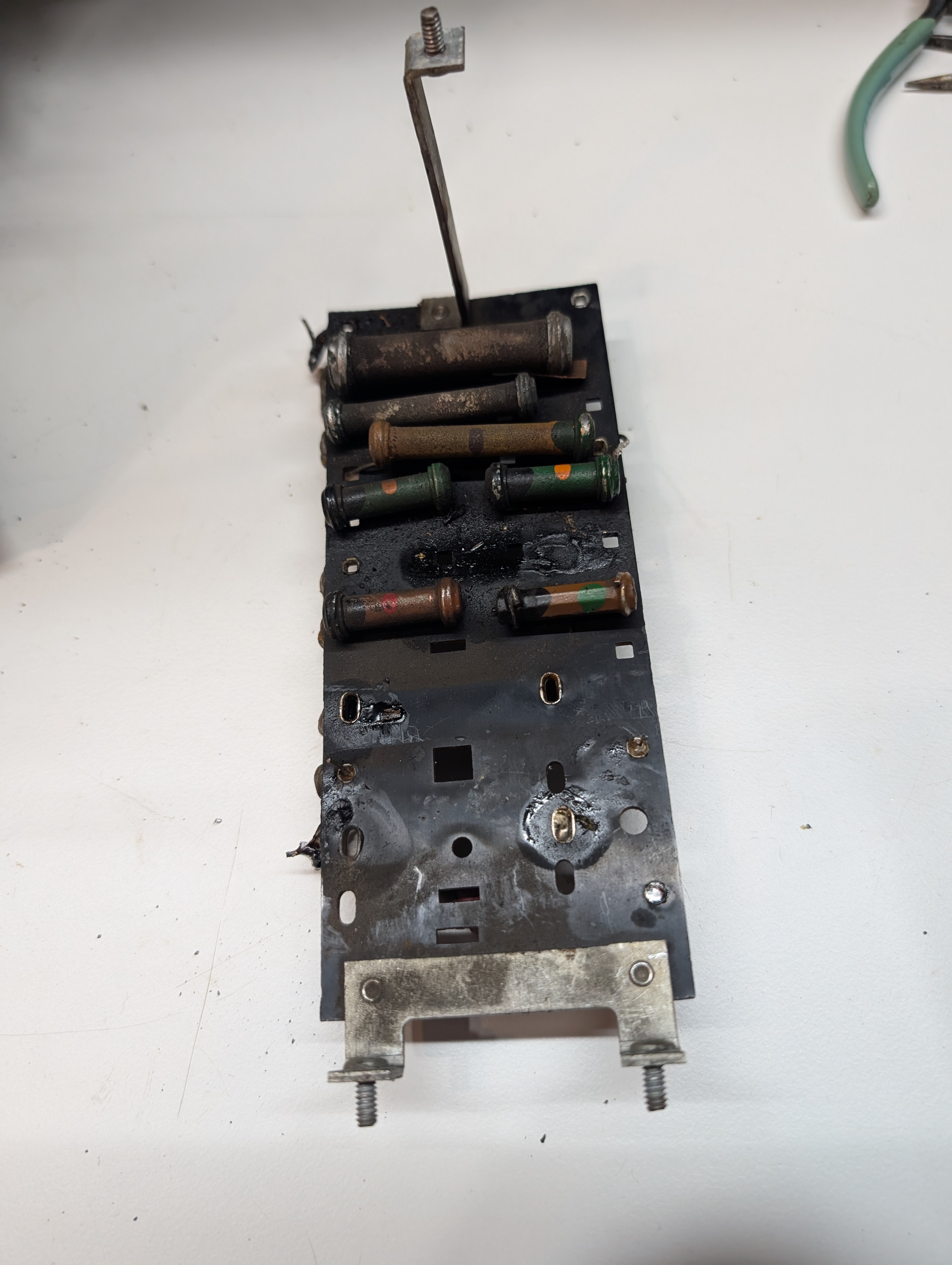
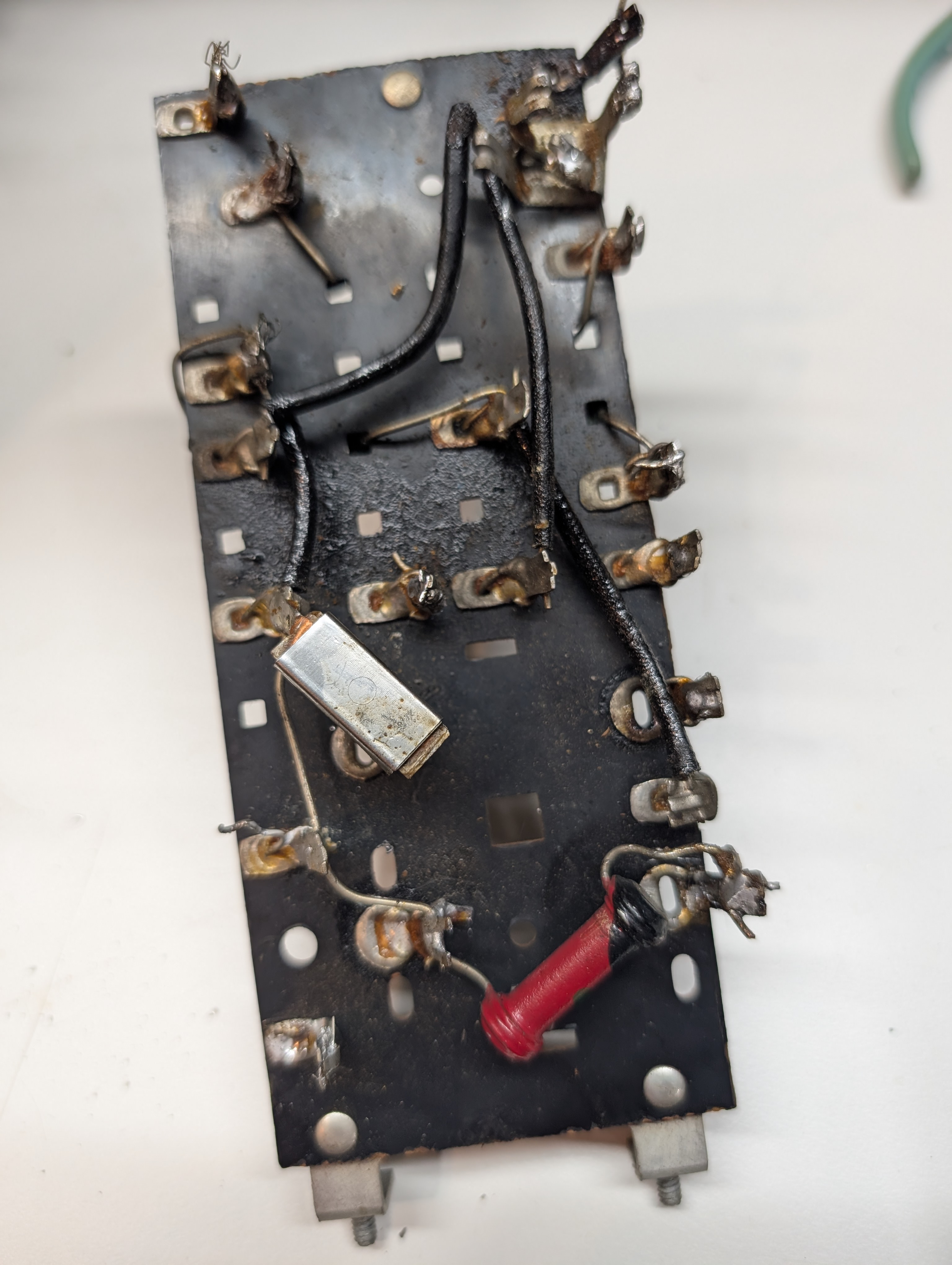
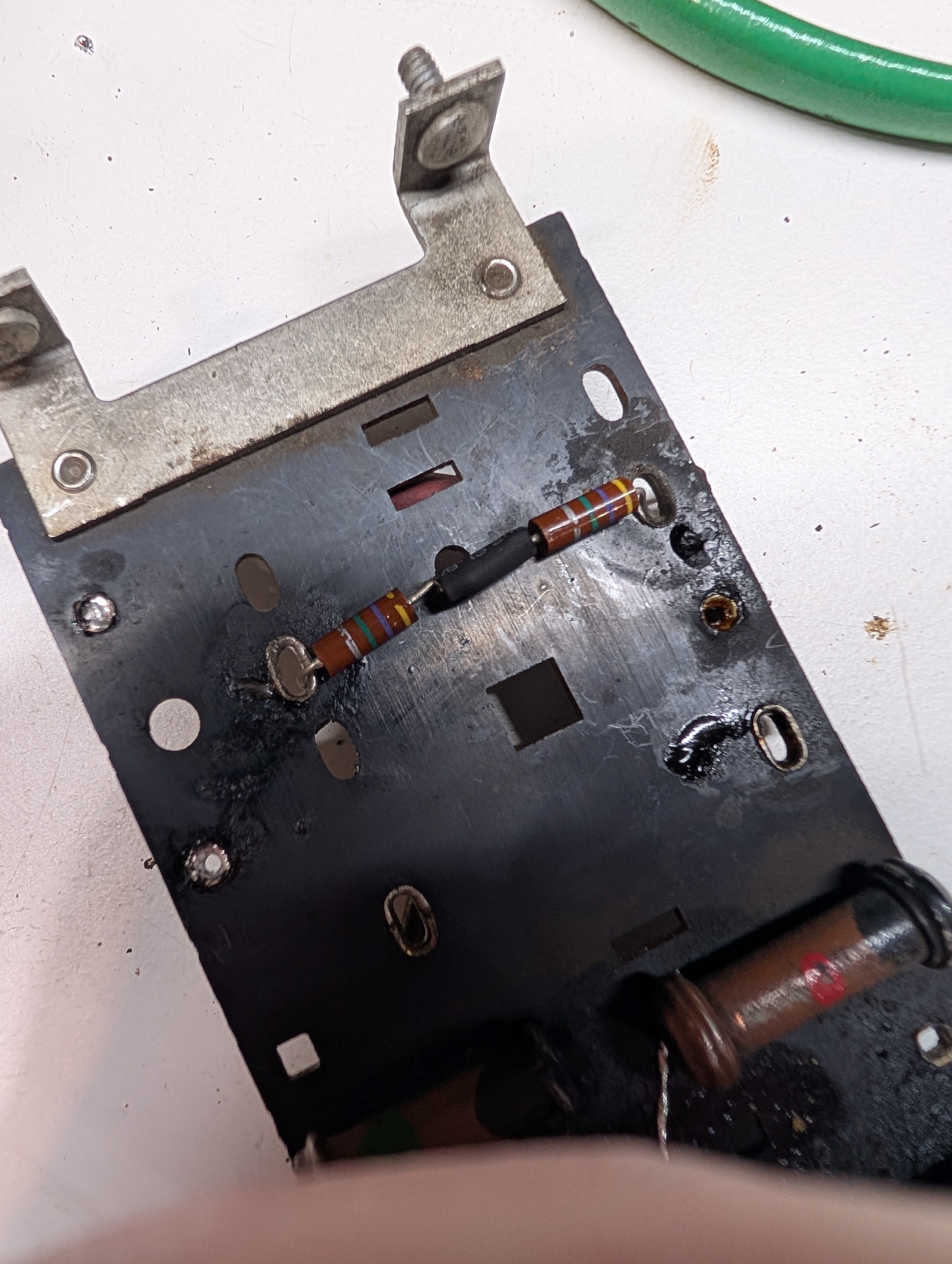
I still use parallel resistors to remedy those that do not exhibit signs of deterioration and simply drifted up a bit more than acceptable.
This one is 2M.
It drifted to 2.7M.
I needed to put 8.5M in paerallel. I had a bunch of 4.7M resistors from a kit from mAmazon (their tolerance more like 10% vs promised 5%), one being 5.7M....I put two of the lowest values, 4.65M in series, in parallel to the original one and got some 2.1M.
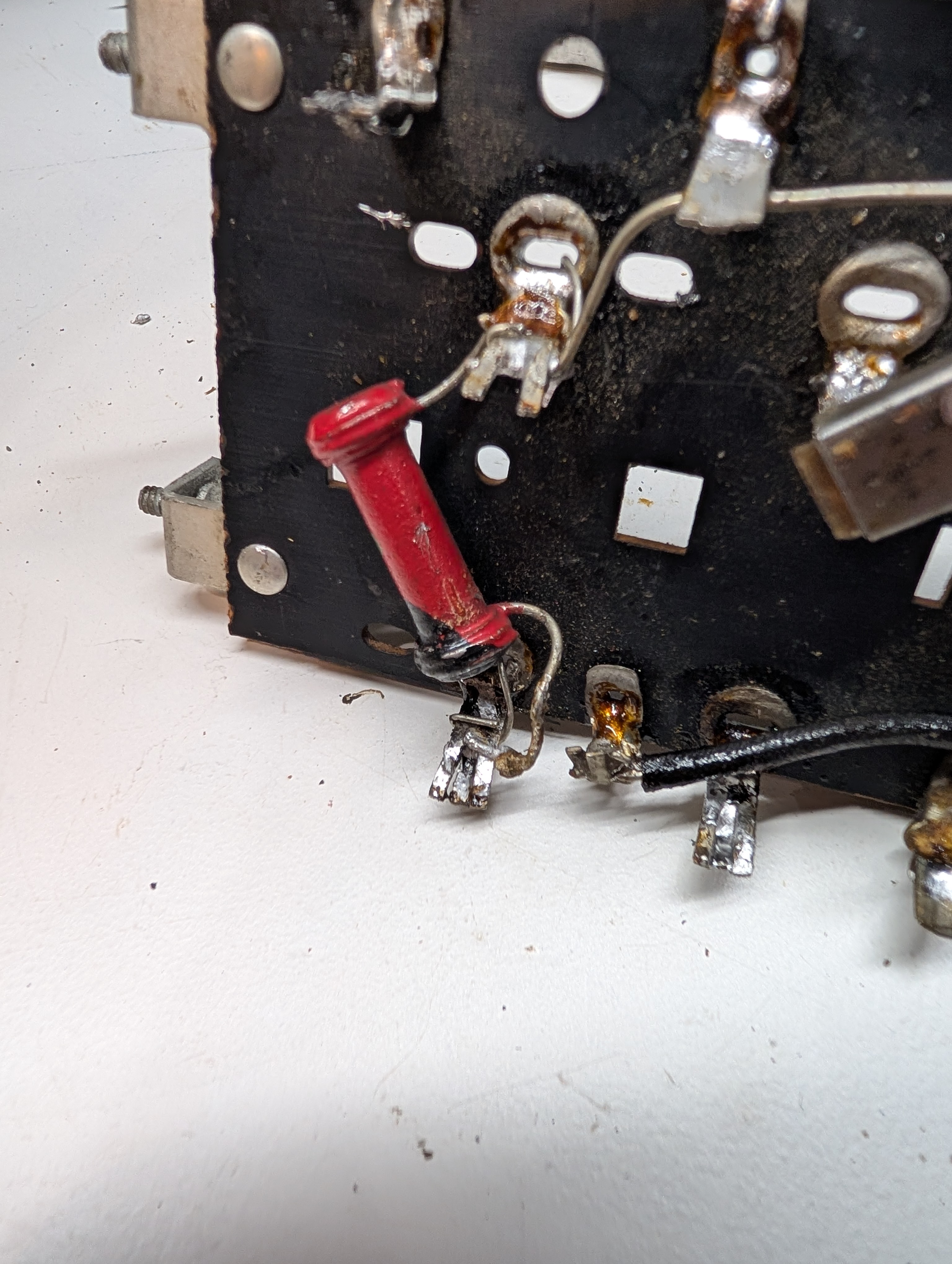
Then I will need to clean the board. Grimy as a tar pit.
People who do not drink, do not smoke, do not eat red meat will one day feel really stupid lying there and dying from nothing.
Posts: 3,188
Threads: 226
Joined: May 2008
City: Omak
State, Province, Country: WA
hello morzh,
looks good nice job on the resistor .
Sincerely Richard
Posts: 18,427
Threads: 622
Joined: Oct 2011
City: Jackson
State, Province, Country: NJ
I skipped the day yesterday.
Wanted to go down the basement, walk on the treadmill and then do some work, but then saw the news about Peter.
So I had to pour me 1-1/2 oz of Vodka, sit down, drink to his memory.
After that, of course, no tredmill fast walk or working on radio was possible.
So, today, other than taking out that board, I restuffed a few caps.
I hope, my photos and my memory will not fail me when I start reconnecting all this.
People who do not drink, do not smoke, do not eat red meat will one day feel really stupid lying there and dying from nothing.
Posts: 711
Threads: 46
Joined: Sep 2009
City: Lapeer, MI
State, Province, Country: USA
Mike, Great work. I would've never thought of paralleling resistors, a nice touch. Nomally I'd rip them out and replace 'em. Be strong. Joe
Courage will follow when Faith takes the lead.
Posts: 18,427
Threads: 622
Joined: Oct 2011
City: Jackson
State, Province, Country: NJ
Joe
often times I do the same, but there are places where a resistor to be within tolerance is more important thn in others (like, to me AVC being 2M or 2.7M would not even make me touch it; this one is in series with the Control grid, so the drop caused by even a small current can affect it) and so some resistors I correct and some I do not.
Those that I do correct, I either replace or parallel.
Those I parallel are the ones that went outside of tolerance but within reason considering the age.
2.7M vs 2M is within reason to me, over 90 years.
Within reason means speed of change. This one went up 30% over 90 years., or 0.33% a year on average.
Then let's say it went to 4M/5M. To me this is bad, same as if it were open. I will yank it and change it.
Another possibility if a large resistor went up so much, that you could parallel the intended value resistor to it (say, 10K went to open or 100K and you parallel a 10K there) and hide it behind the original resistor. Sometimes I do that too.
People who do not drink, do not smoke, do not eat red meat will one day feel really stupid lying there and dying from nothing.
Posts: 5,654
Threads: 56
Joined: Sep 2008
City: Sandwick, BC, CA
Mike;
It seems to be a matter of production quality of the resistors used, in that Westinghouse 801 that I repaired all of the resistors, except one, were within tolerance, if not spot on, and they were all BED code "dogbones" I've heard that the late 20s RCA AC sets are the same, but will verify.
Regards
Arran
Posts: 1,797
Threads: 55
Joined: Feb 2015
City: Roseville, MN
Arran,
We also have to consider the environment they endured. For these higher values not much current is involved but it may have been physically close to a high temperature component or humid conditions which, over time, will affect the value. And that's when the quality you bring up comes to focus.
Posts: 18,427
Threads: 622
Joined: Oct 2011
City: Jackson
State, Province, Country: NJ
Rod
I've seen 2M being open or 10M.
Some of the 100K or 250K or so in Philco 20, I remember were fully open, but those were at least conducting something. Those that come from the wire-wound, one feeds the detector plate and the other Screen Grid. Forgot which one.
People who do not drink, do not smoke, do not eat red meat will one day feel really stupid lying there and dying from nothing.
Posts: 18,427
Threads: 622
Joined: Oct 2011
City: Jackson
State, Province, Country: NJ
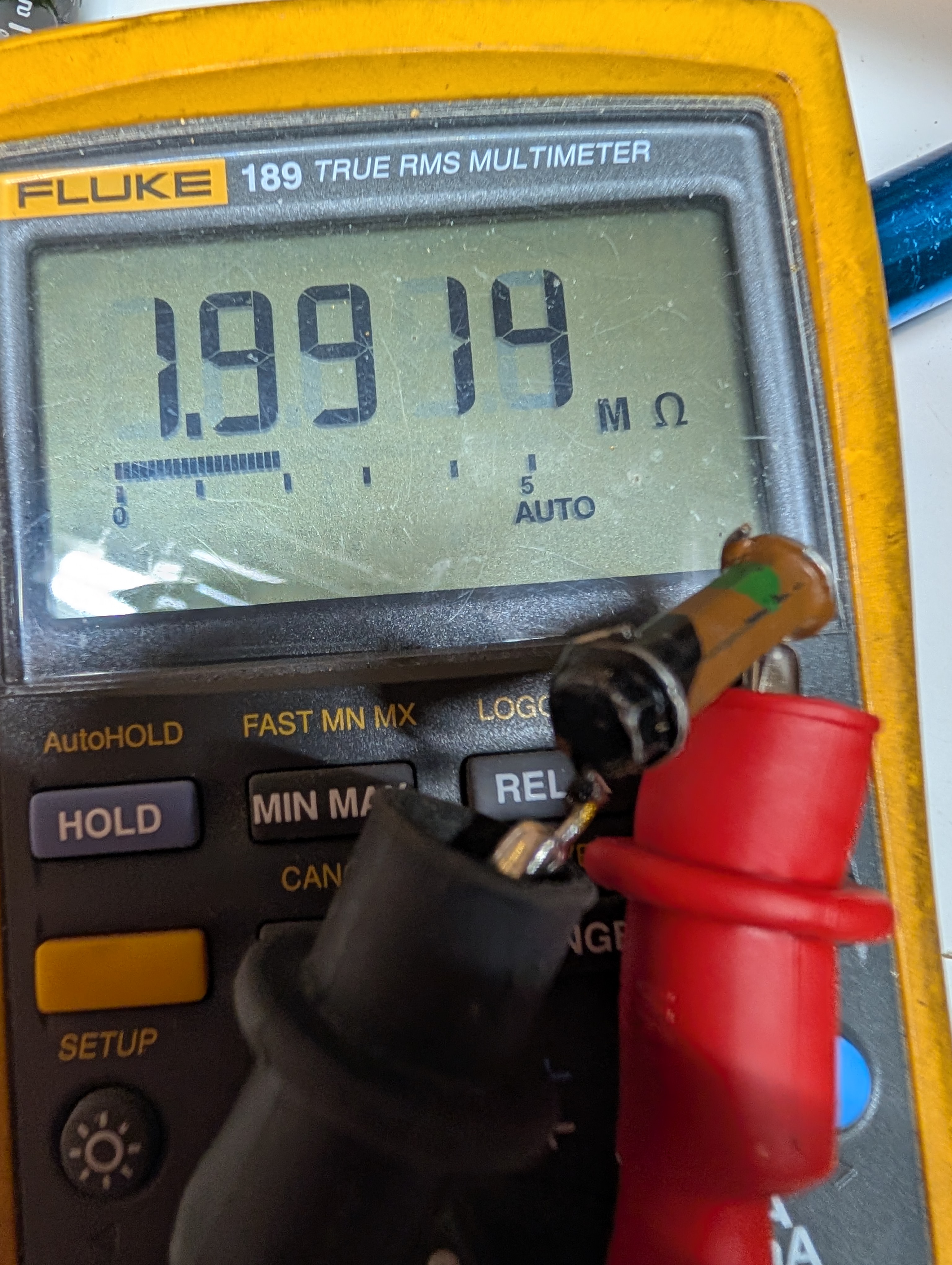
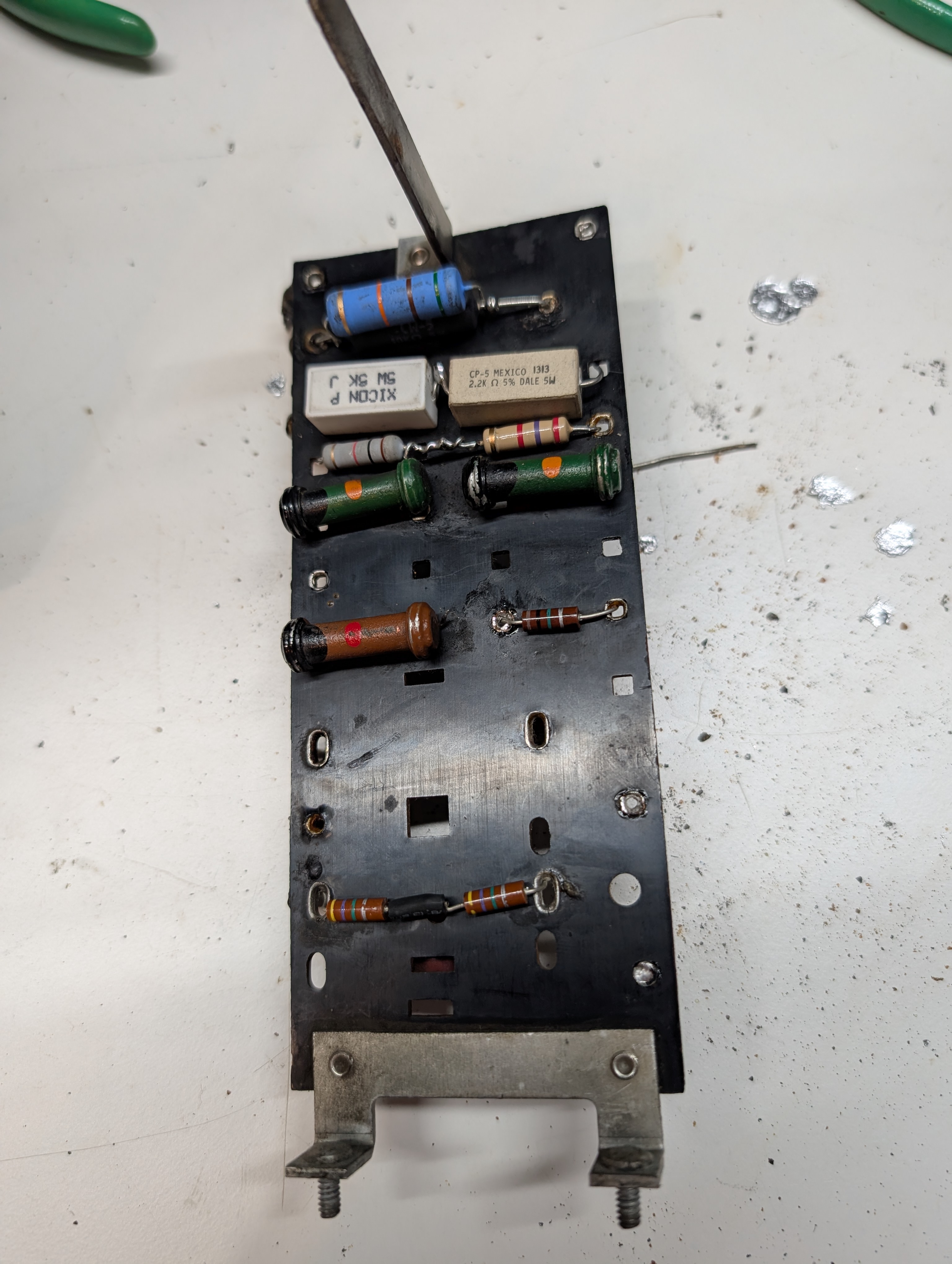
Speaking of out of tolerance resistors, this type I change.
A 1M that is exhibiting 2M.
Now, there are three resistors, R7 / 3.5K, R6 / 6,5K and R5 / 8.5K.
Obviously they are power-dissipating type, as all were discolored.
All went down in resistance (I've observed that with Philco power dividers in Philco 60 and similar Philcos, for the power divider resistors, a lot).
The 3.5K was 2.5K and the only one that retained some colors and did not break when simply touched.
The 6.5K was broken (I broke it but without any effort, probably just touched during the board handling), and the 8.5K was 5K before it also broke when slightly touched.
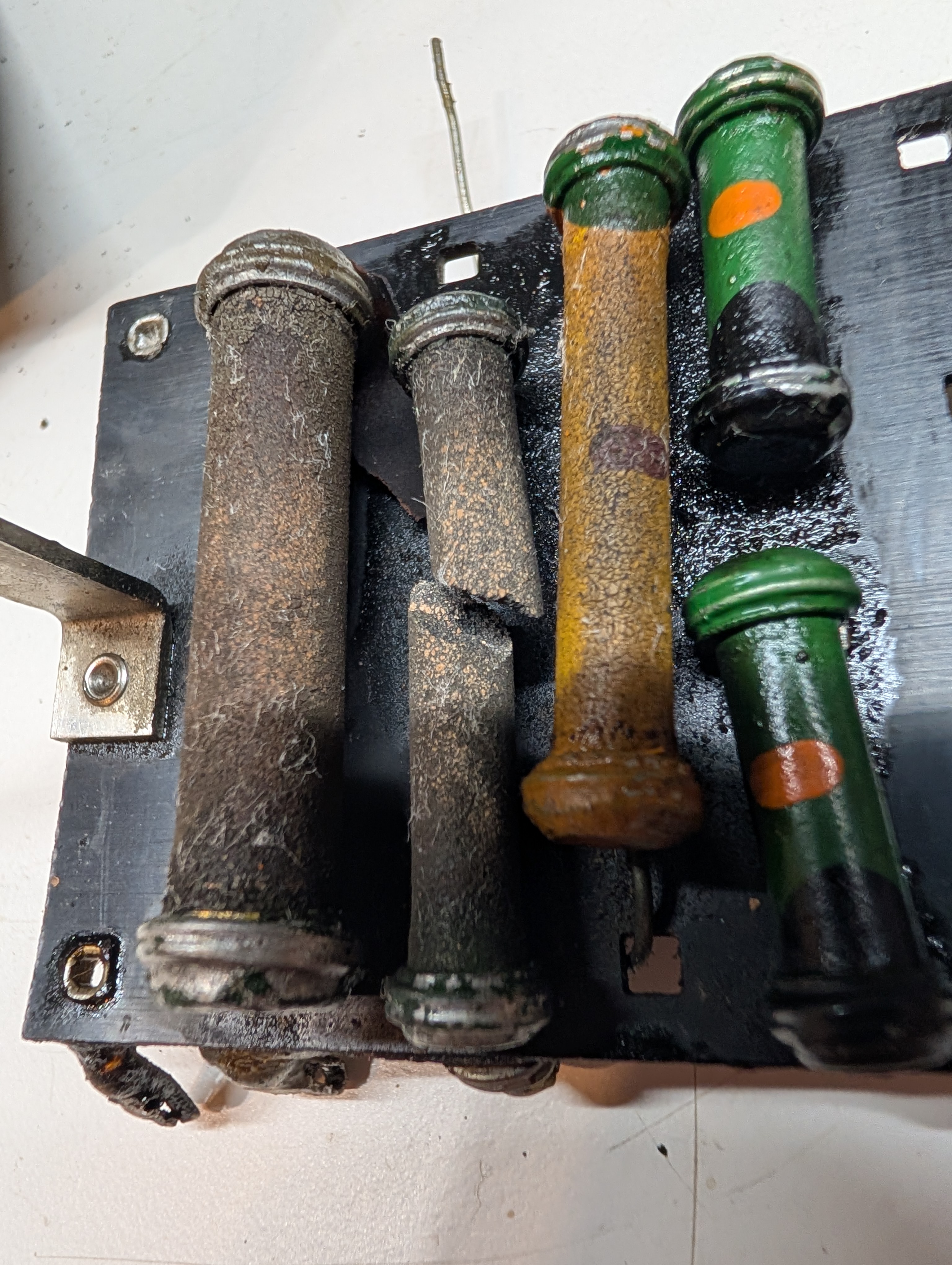
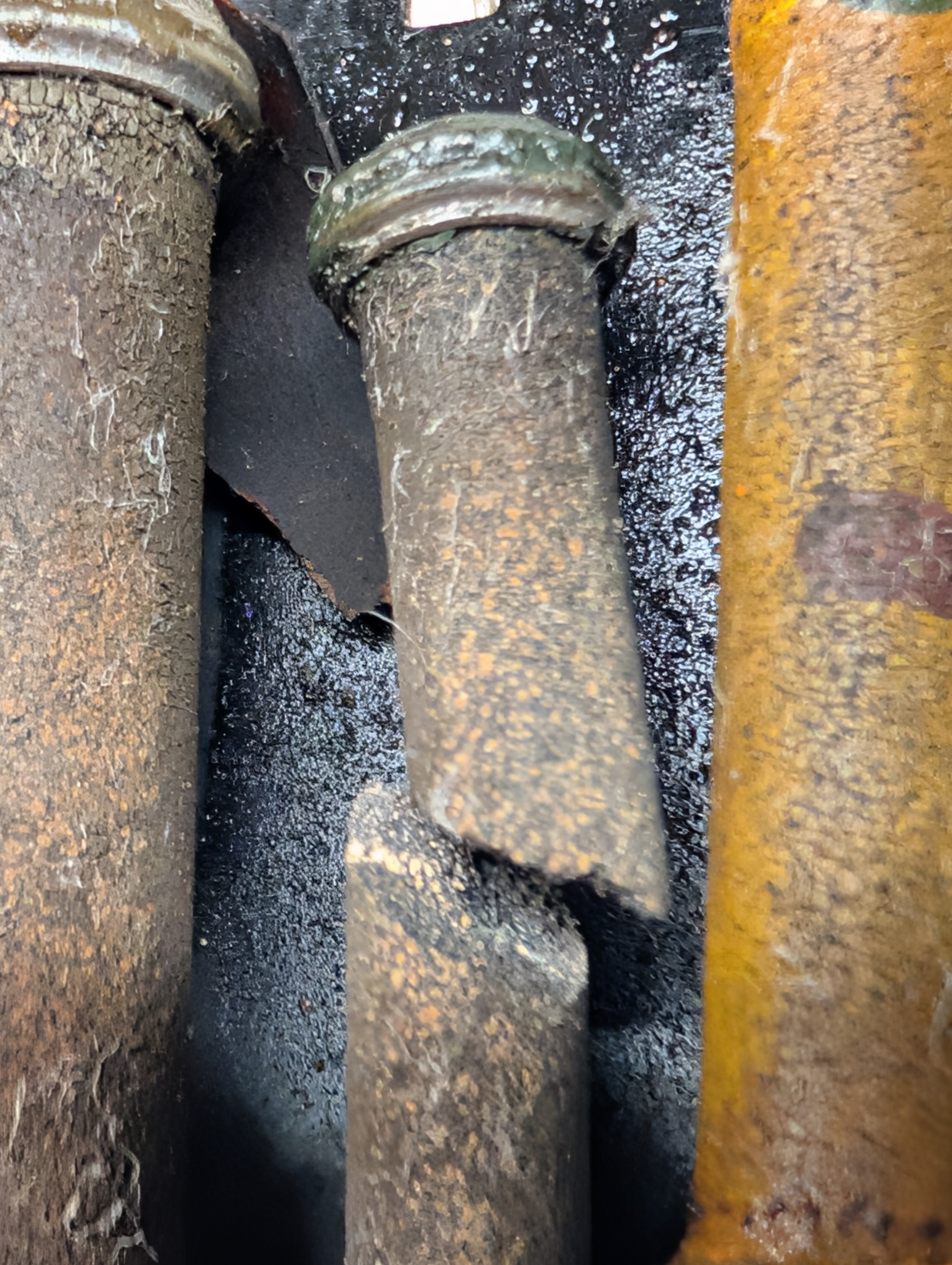
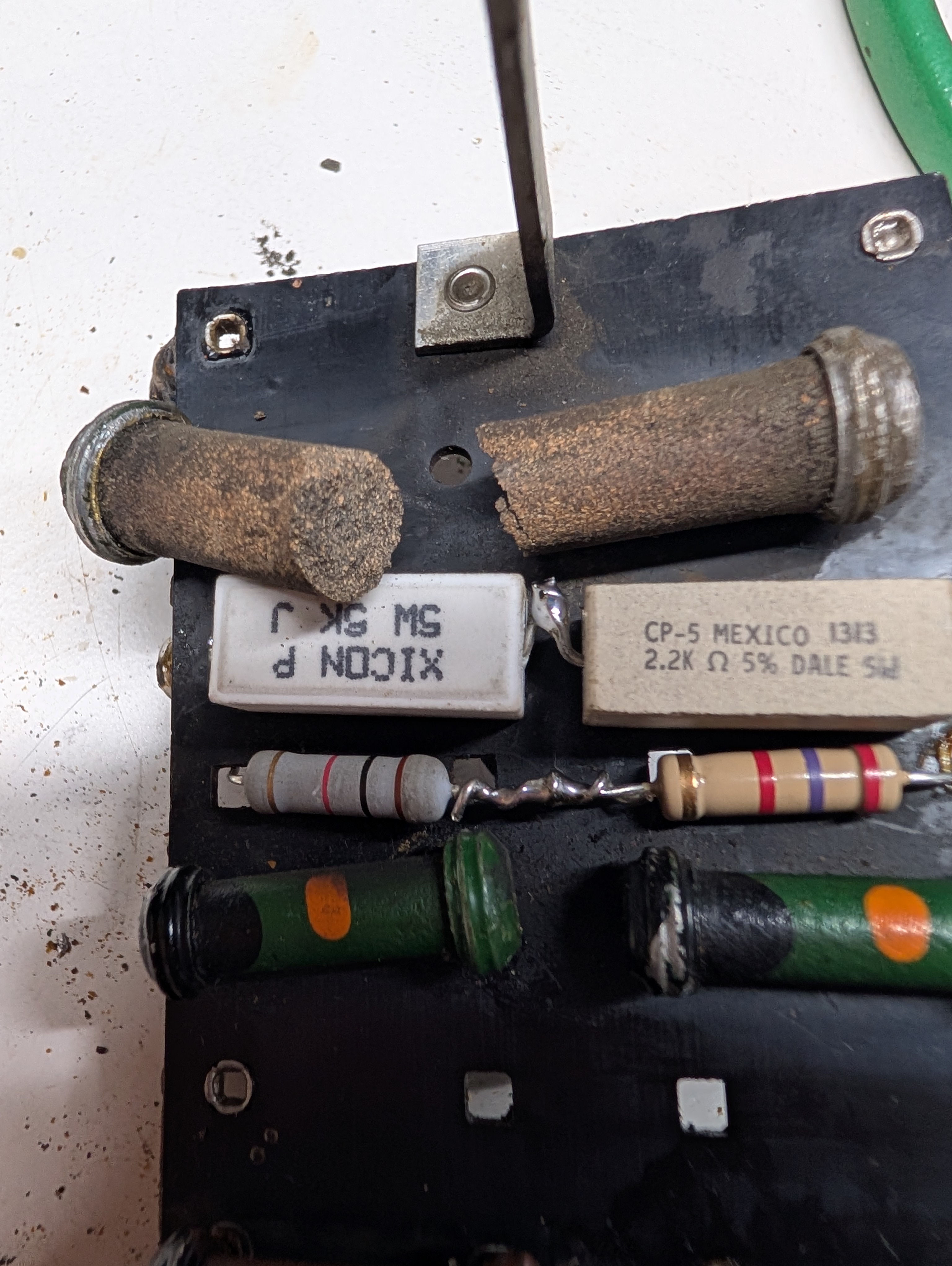
I was able to use paralleling/serializing and got pretty close to the requir ed nominals, plus I think I have good margin on the power ratings.
The rest of the resistors were either right on the money, or pretty close, so I left them.
This is how it looks now.
People who do not drink, do not smoke, do not eat red meat will one day feel really stupid lying there and dying from nothing.
Posts: 5,654
Threads: 56
Joined: Sep 2008
City: Sandwick, BC, CA
Mike;
I guess I forgot to post my previous comment about replacing the "Black Beauty" cap. I was thinking that if you had some thick paper you could make a replica of one of those tar filled caps.
The Rogers 10-60 I have was similar to this RCA 140, it also has two resistor boards, but they mount them parallel to the rear apron, and the left side with standoffs, and connected them to the tube sockets, and other components, with rubber/gutta percha wire. Someone had already replaced some of the power resistors mounted on them, crudely, so I removed them, and after confirming whether the values were correct, or not, reinstalled them. They used wire wound resistors with a black enamel or cement coating, which look like "Dogbone" style carbon resistors anyhow, so i replaced the rest using similar resistors, brown or black. In that set the ends of the resistors and caps can be seen after you remove the bottom cover, so I decided to restuff the original caps, and old replacement caps, and restuffed some suitable looking paper caps from my junk collection. I wasn't concerned about whether the parts were factory originals so much as hating the look of daffodil yellow replacements in a pre war radio, if I could make it look like maybe some of the parts were replaced during it's service life that was fine with me.
Regards
Arran
Posts: 3,188
Threads: 226
Joined: May 2008
City: Omak
State, Province, Country: WA
Hello morzh,
Yes, when I was at work friday I thought of Peter alot !.
I hear you on remembering how to wire this I have my Philco 38-10t that is still not finished.
Sincerely Richard
Posts: 711
Threads: 46
Joined: Sep 2009
City: Lapeer, MI
State, Province, Country: USA
Mike, I've never seen a dogbone break like that. Fossilized is what it looks like. I don't think the replacements will look like that 90 years down the road! Joe
Courage will follow when Faith takes the lead.
Posts: 1,519
Threads: 69
Joined: Nov 2012
City: Kansas city, MO.
Here is one I pulled out of an rca victor model R-14.
It burned in half. It was under one of those resistor boards and the board was riveted to the chassis. Real pain to replace.
https://imgur.com/a/du7wJnp
Posts: 117
Threads: 25
Joined: Jul 2006
City: Lebanon
State, Province, Country: NJ
Carbon comp resistors will typically increase in value over time and environment even without being powered. I have an assortment of Allen Bradley carbon comp 1/2W resistors in original packaging from the 1960's and almost everyone increased in value by 10-20%; the higher value ones more increased in value than the lower values.
Steve D
Users browsing this thread: 4 Guest(s)
|
|
Recent Posts
|
|
Stromberg Carlson 1500 Squeal
|
| And life just keeps getting more complicated. By dconant.
Dittos'Jimradio — 08:01 AM |
|
Plug Voltages Needed For A 1943 CRV-20130 Power Supply
|
| That looks a lot like an aircraft connector of some kind, even if it's a U.S.N power supply. I have a book somewhere abo...Arran — 02:56 AM |
|
Plug Voltages Needed For A 1943 CRV-20130 Power Supply
|
| hello david,
I have a similar generator in my collection that features a cast iron, single-cylinder Briggs & Stratt...radiorich — 01:00 AM |
|
under chassis parts locator diagram for 1938 Zenith 9s262
|
| Has anyone gone to the trouble of creating an under chassis parts locator image? Yes, I can identify components by foll...bobloney — 08:57 PM |
|
Plug Voltages Needed For A 1943 CRV-20130 Power Supply
|
| Try looking at this site the book mark is for a old generator that I was given. David https://radionerds.com/index.ph...David — 08:36 PM |
|
Plug Voltages Needed For A 1943 CRV-20130 Power Supply
|
| Hello Everyone,
I am looking for voltage identification for all the pin positions on the socket of a CRV-20130 power su...Tonym4704 — 08:16 PM |
|
Philco P45-6365 Universal Transformer Instruction Manual
|
| Can anyone guide me to where this may be found?GRG — 03:00 PM |
|
54C Complete Teardown/Rebuild
|
| I don't think that I have encountered a 12Z3 before, curious how it uses one of those but includes a #43, which is a 25 ...Arran — 02:17 PM |
|
HiFi (Chifi) tube amp build - but my own design.
|
| It's the other forum. I'm also in DIY, but mostly read there. Honestly, I kinda jumped into this without much thought to...TV MAN — 10:43 AM |
|
Philco 71 Code 125
|
| Hello,
I am in need of a schematic for this radio. Mine has the three separate circular tube shields and a shadow me...dconant — 08:06 AM |
|
Who's Online
|
| There are currently no members online. |

|
 
|









