Posts: 2,327
Threads: 23
Joined: Jul 2020
City: Greenlawn
State, Province, Country: NY
Does anyone know what to clean a cadmium plated chassis (I assume that this is cad plated) without removing the cadmium?
"Do Justly, love Mercy and walk humbly with your God"- Micah 6:8
"Let us begin to do good"- St. Francis
Best Regards,
MrFixr55
Posts: 18,427
Threads: 622
Joined: Oct 2011
City: Jackson
State, Province, Country: NJ
Arran
It has 1) C12, 4uF for 2nd RF cathode feedback, 2) C49, 10uF for 2nd Det cathode feedback and 3) C39, 10uF for LC power filter for B+ that goes everywhere other than the pushpull output power.
I had some reasonably modern saved axials (a Xicon 4.7uf, a Rubicon and an IC 10uF) I extracted from the radios I restored before, where they were out of place, so I used them; tthsy are all 450 or 500V. I just wanted to use them up; the first two cap can be 25-50V rated.
MrFixr
I do not make my chassis' look like they just left the factory's division intended for export to royals around the world, so, being not very proud guy, I use Windex, and when Windex struggles, I use odorless (???!!!) mineral spirits.
Neither is known to strip cadmium.
The OMS did a great job on hat smaller can, the photo of which I will show here later.
People who do not drink, do not smoke, do not eat red meat will one day feel really stupid lying there and dying from nothing.
Posts: 1,797
Threads: 55
Joined: Feb 2015
City: Roseville, MN
I restored a Phonola chassis from Italy that was cadmium and completely coated with the oxide. I used a diluted mixture of Naval Jelly and water applied with an acid brush. The oxide was everywhere so the brush was really effective. I could see where the oxide didn't appear on some of the parts that were stainless or maybe plated, like the tube sockets.
Posts: 18,427
Threads: 622
Joined: Oct 2011
City: Jackson
State, Province, Country: NJ
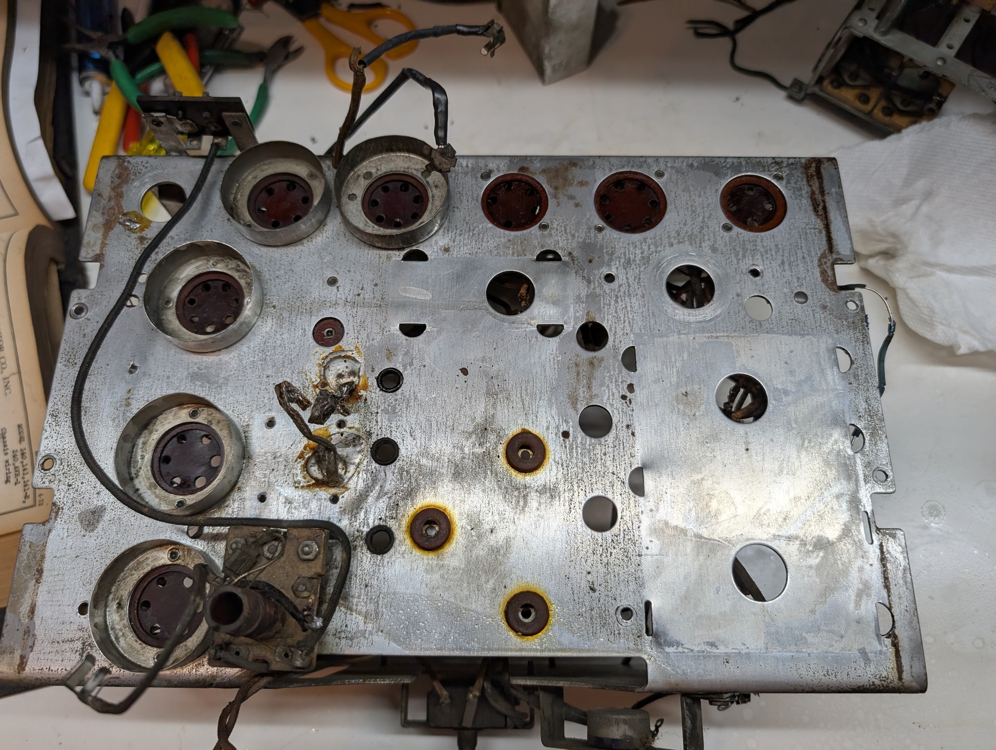
Cleaning.
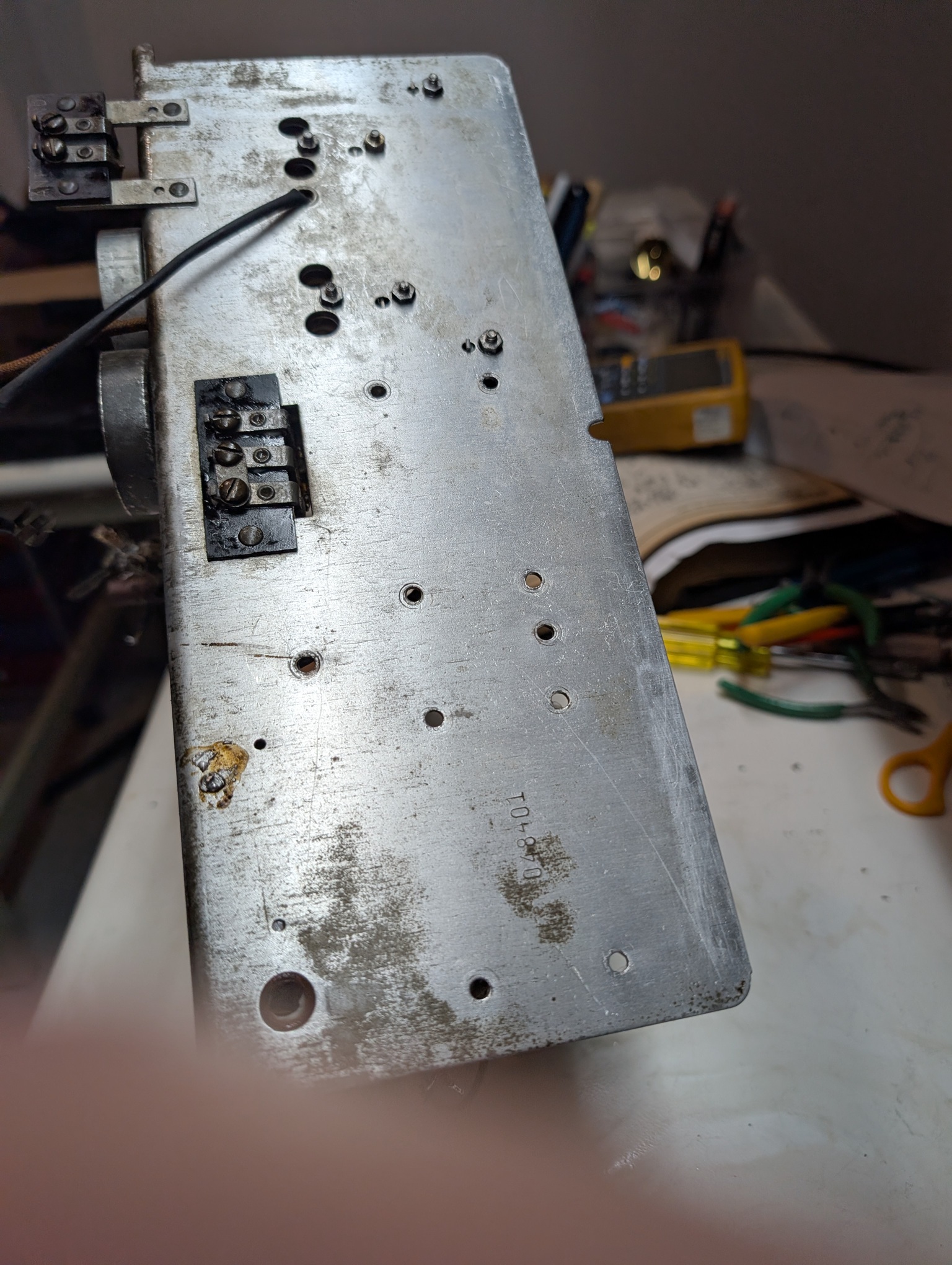
So, Windex works some.
So does OMS.
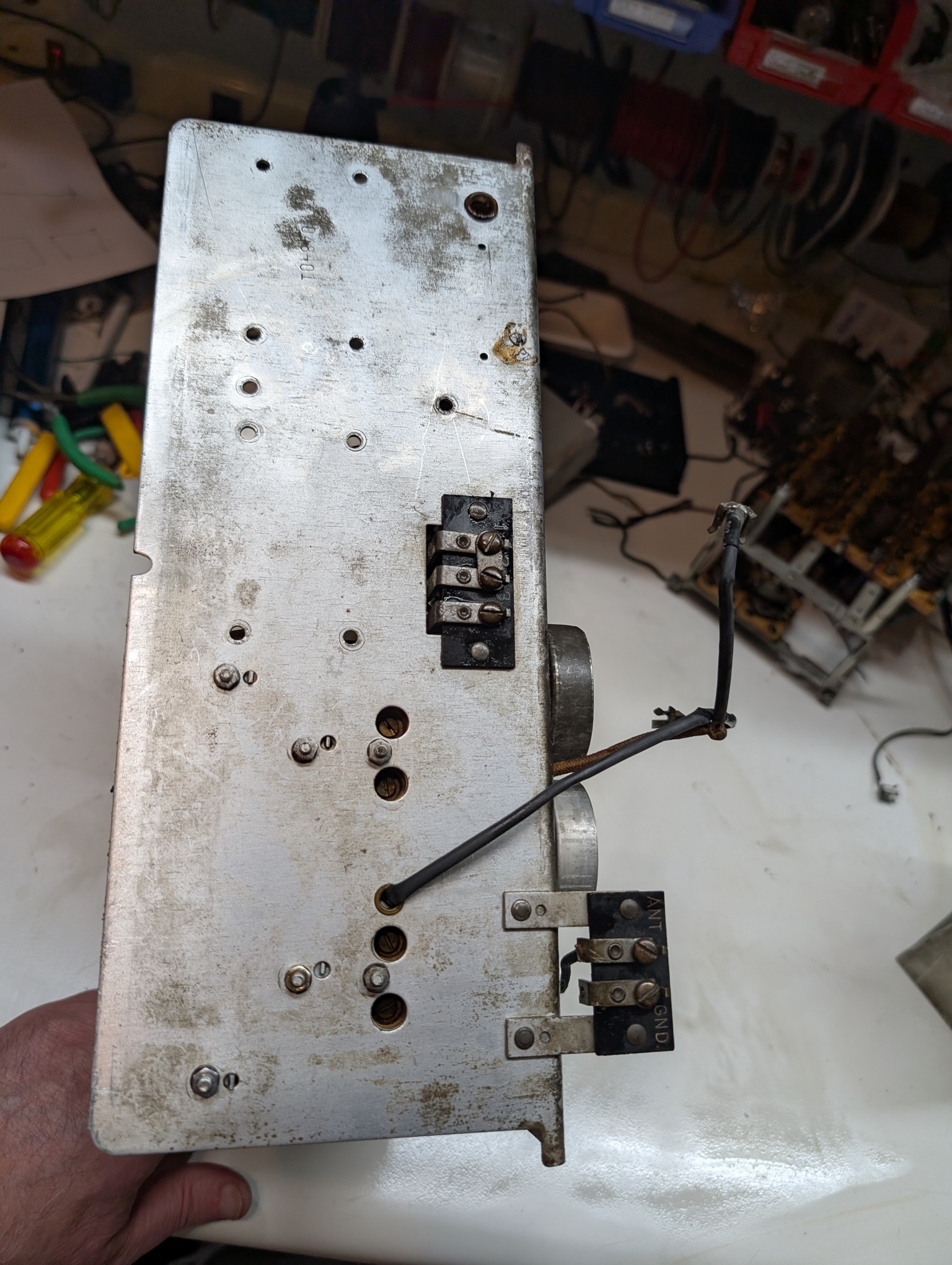
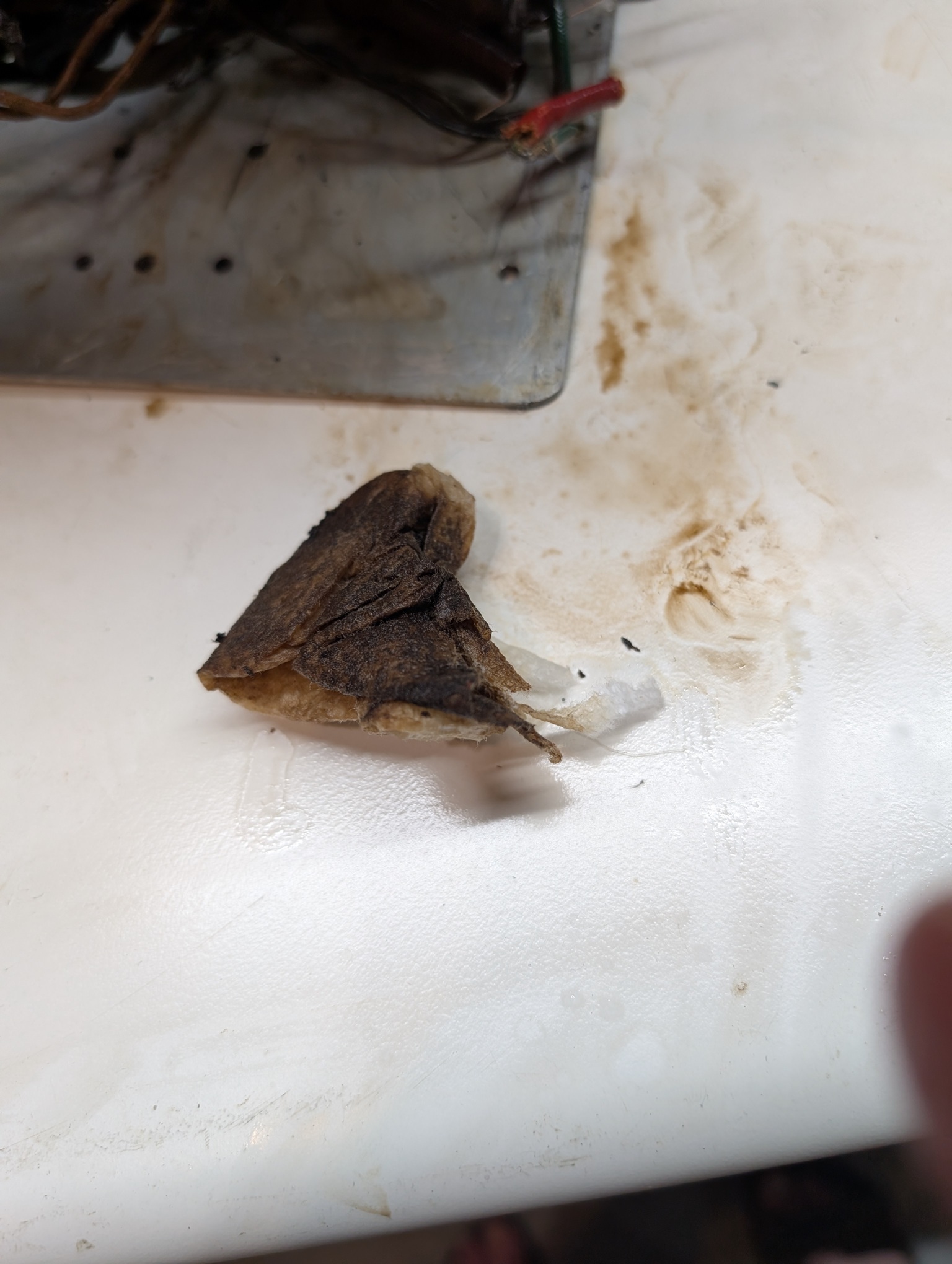
Eventually, I applied some Goop and it did some extra work, judging by the result and the way the paper towel looked after wiping it off.
So, this is the way the top looked before cleaning.
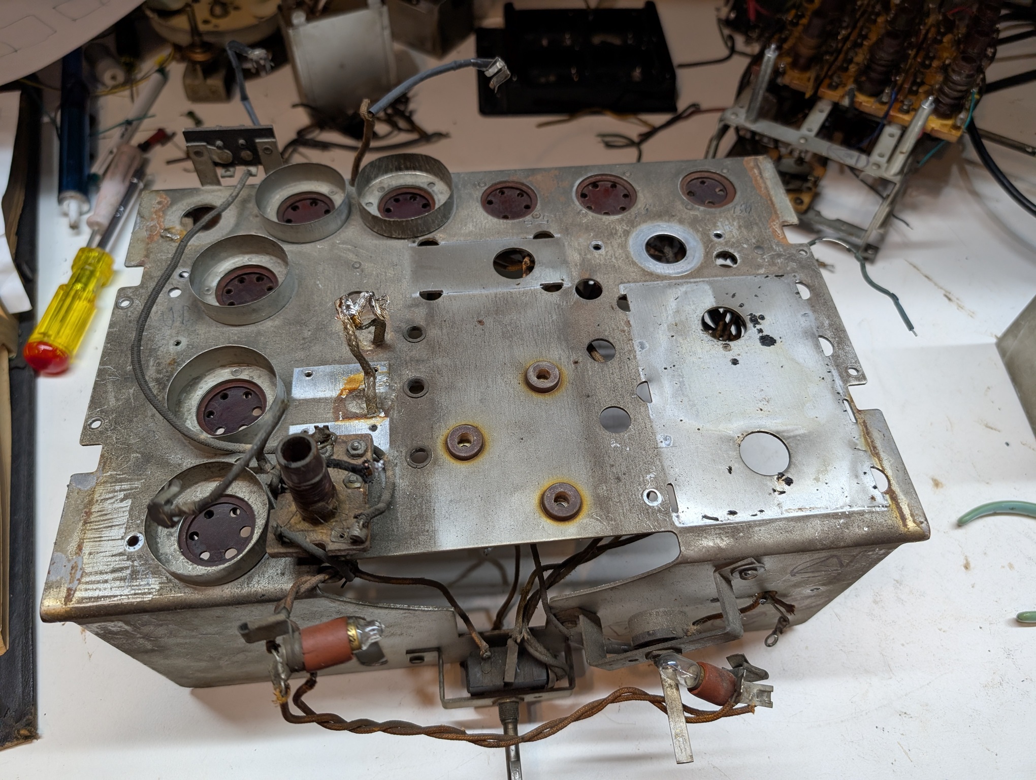
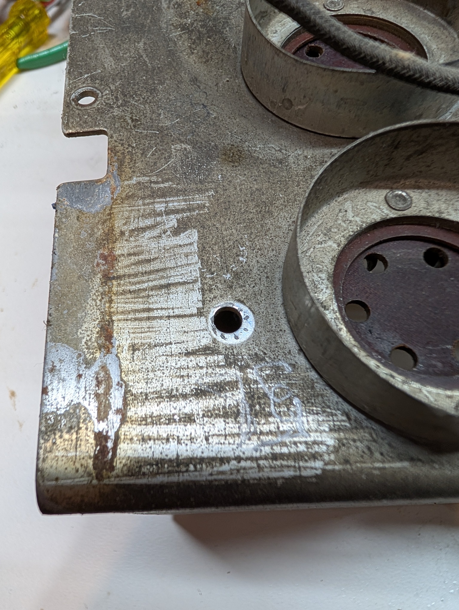
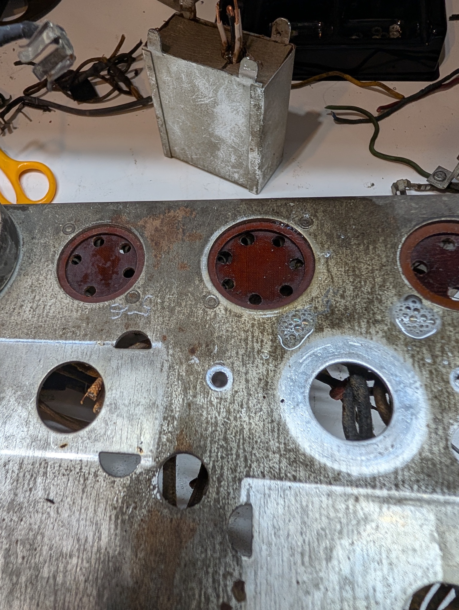
After some cleaning with OMS
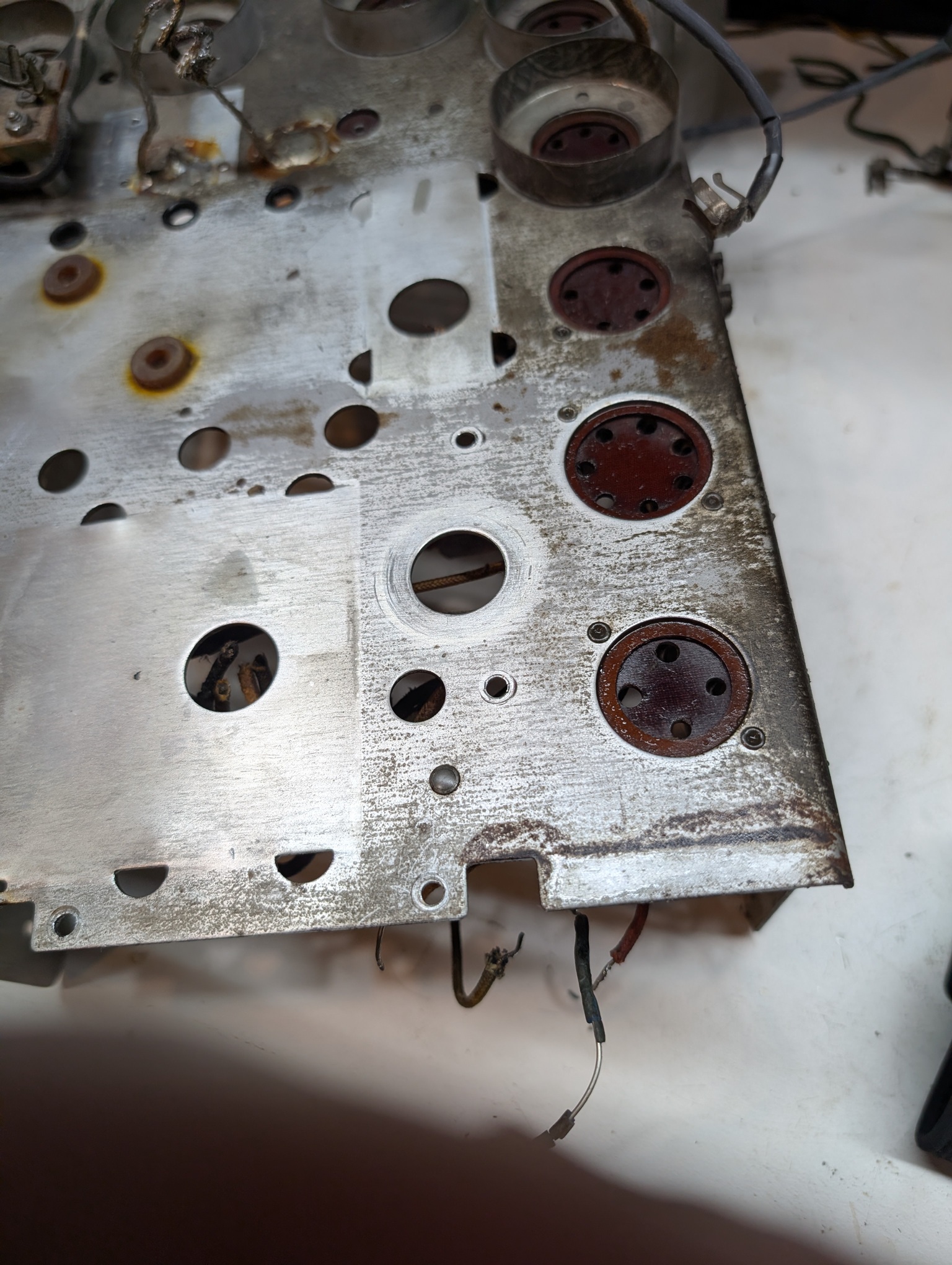
And after Goop and some OMS. The surface has some pitting, and so whatever is inside it, does not come out, not with toothbrush, or anything else. And judging by the paper stayingclean after wiping, I decided that the perfect is the enemy of good enough.
The rear after OMS
And then after Goop and OMS
The inner part under one of the transformers (the transformer seems OK; I hope it is not indicative it has some turn short)
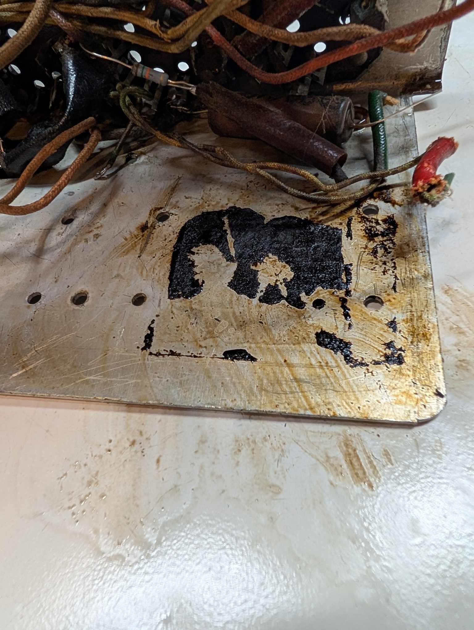
OMS applied
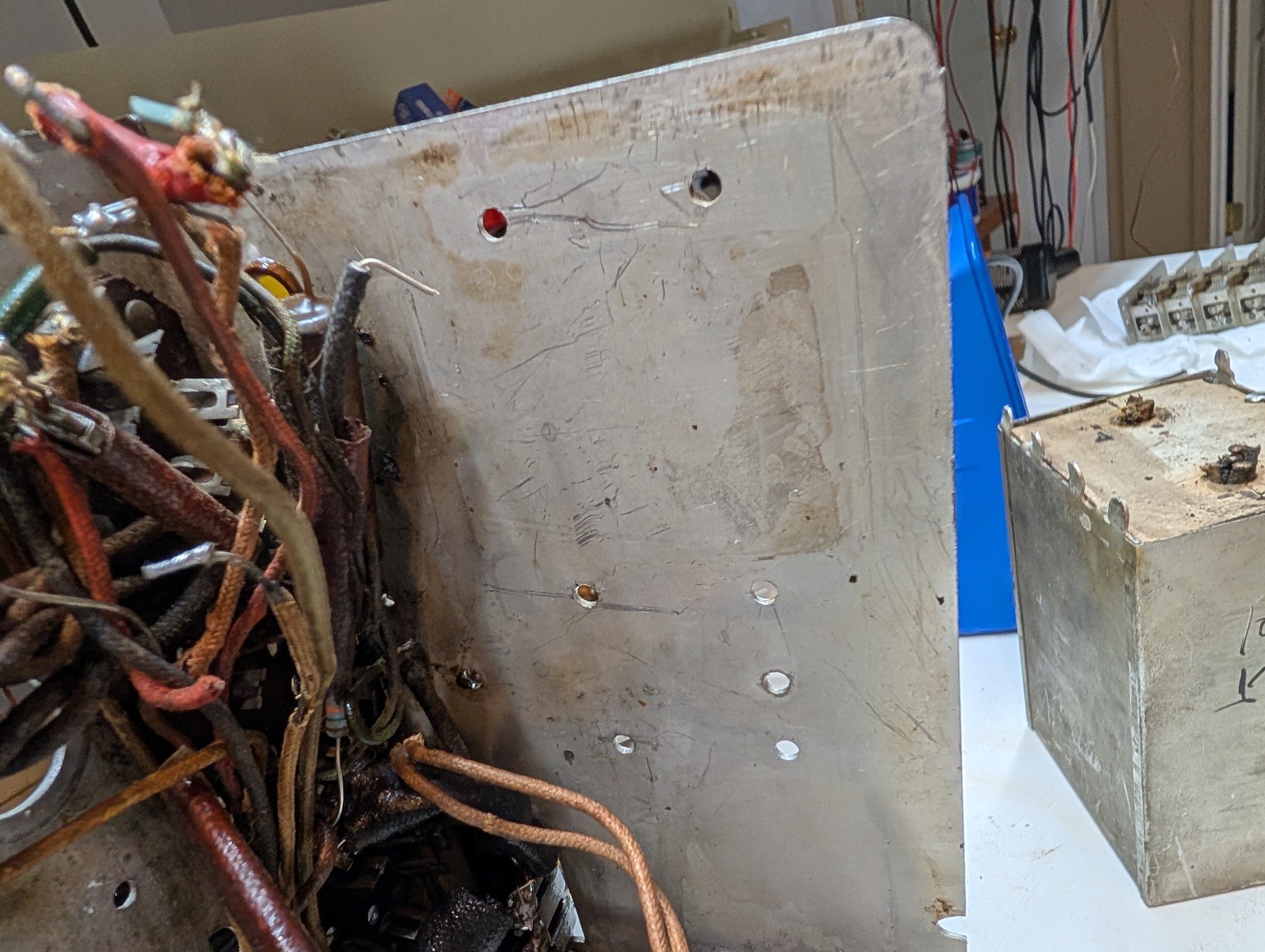
And, eventually, the can is prepped for freezing. Needed unbending the small tabes holding the paper cover.
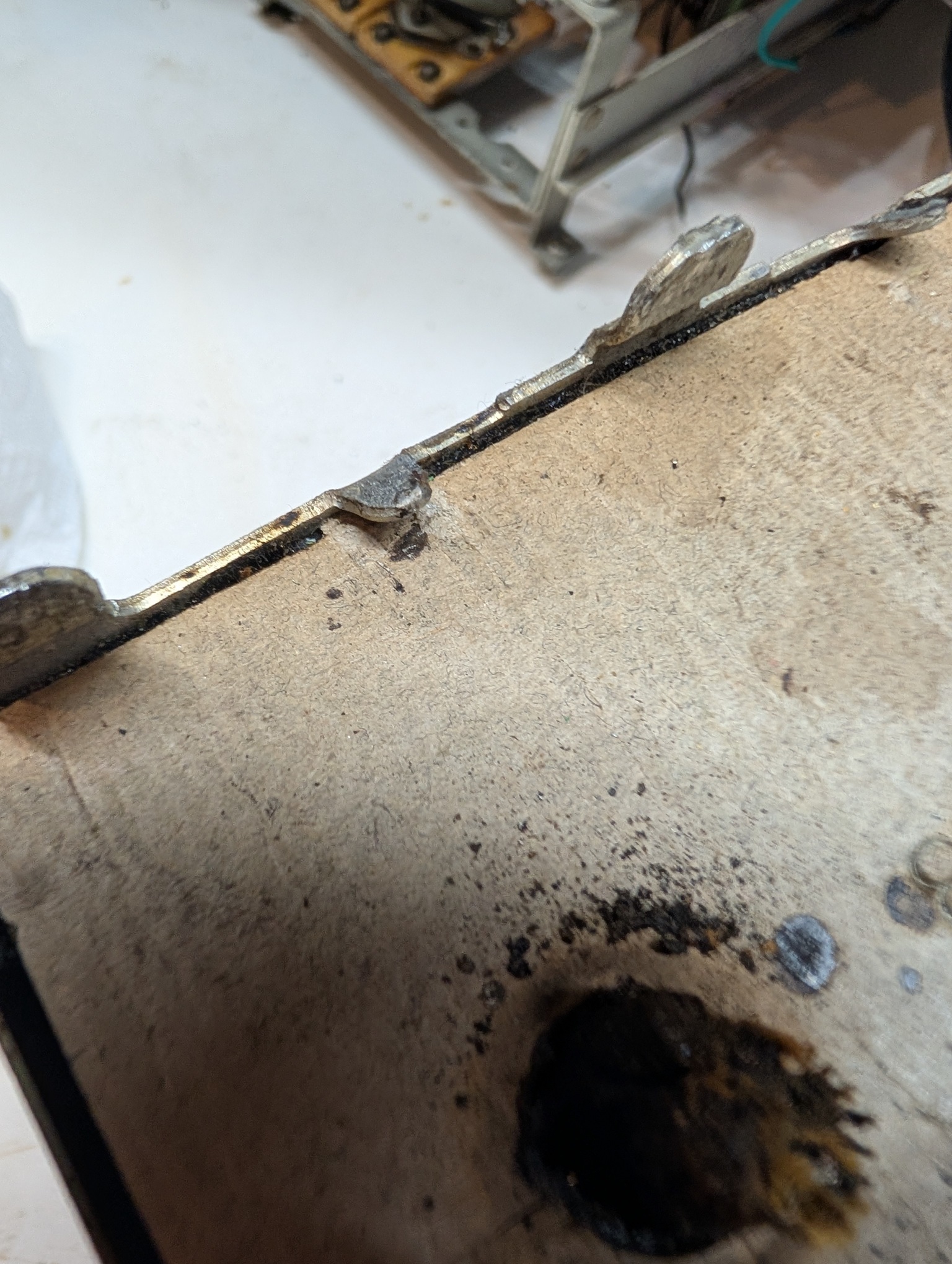
I wrapped it in two plastic bags and stuck in the freezer box.
When extracted, I will try to use a wood square and a hammer and give it some taps all around the sides, to try rto break the bond.
The way I did it to the smaller can is not likely to work: the can weight 9.8lbs (I actually weighed it today). So the corkscrew or even an anchor bolt are right now at the bottom of my "try to" list.
It is at least twice the weight of the larges of the Philco cans I have dealt with (from 112 or 96 models)
So, it is getting frozen and I am taking some rest.
People who do not drink, do not smoke, do not eat red meat will one day feel really stupid lying there and dying from nothing.
Posts: 5,654
Threads: 56
Joined: Sep 2008
City: Sandwick, BC, CA
Quote: (Arran
It has 1) C12, 4uF for 2nd RF cathode feedback, 2) C49, 10uF for 2nd Det cathode feedback and 3) C39, 10uF for LC power filter for B+ that goes everywhere other than the pushpull output power.
I had some reasonably modern saved axials (a Xicon 4.7uf, a Rubicon and an IC 10uF) I extracted from the radios I restored before, where they were out of place, so I used them; tthsy are all 450 or 500V. I just wanted to use them up; the first two cap can be 25-50V rated.)
Mike;
I hope that all goes well with those electrolytics, I would hate to have to extract the smaller can again if something goes wrong with one of the ones inside. Maybe leave enough of a gap under the tabs rather then peening them over completely so you can get it out again with less drama. Sometimes I worry about restuffing the chassis top electrolytic cans in a set, so I leave a way to get them open without uncrimping the can, if I'm using an electrolytic inside.
Regards
Arran
(This post was last modified: 07-19-2026, 04:42 PM by Arran.)
Posts: 18,427
Threads: 622
Joined: Oct 2011
City: Jackson
State, Province, Country: NJ
Arran
I honestly think they outlive me...for whatever reason 
Oh, and to hold that can in place a very slight bend will do. Does not have to be full bend.
People who do not drink, do not smoke, do not eat red meat will one day feel really stupid lying there and dying from nothing.
Posts: 18,427
Threads: 622
Joined: Oct 2011
City: Jackson
State, Province, Country: NJ
Thought of installing the tuning cap back but then decided to take care of the potentiometers first.
The tone ctl also has the switch, and the switchm when made, was in tens of Ks.
Luckily, it opens easy: the tabs are pushed through the holes and the back cover is pulled out.
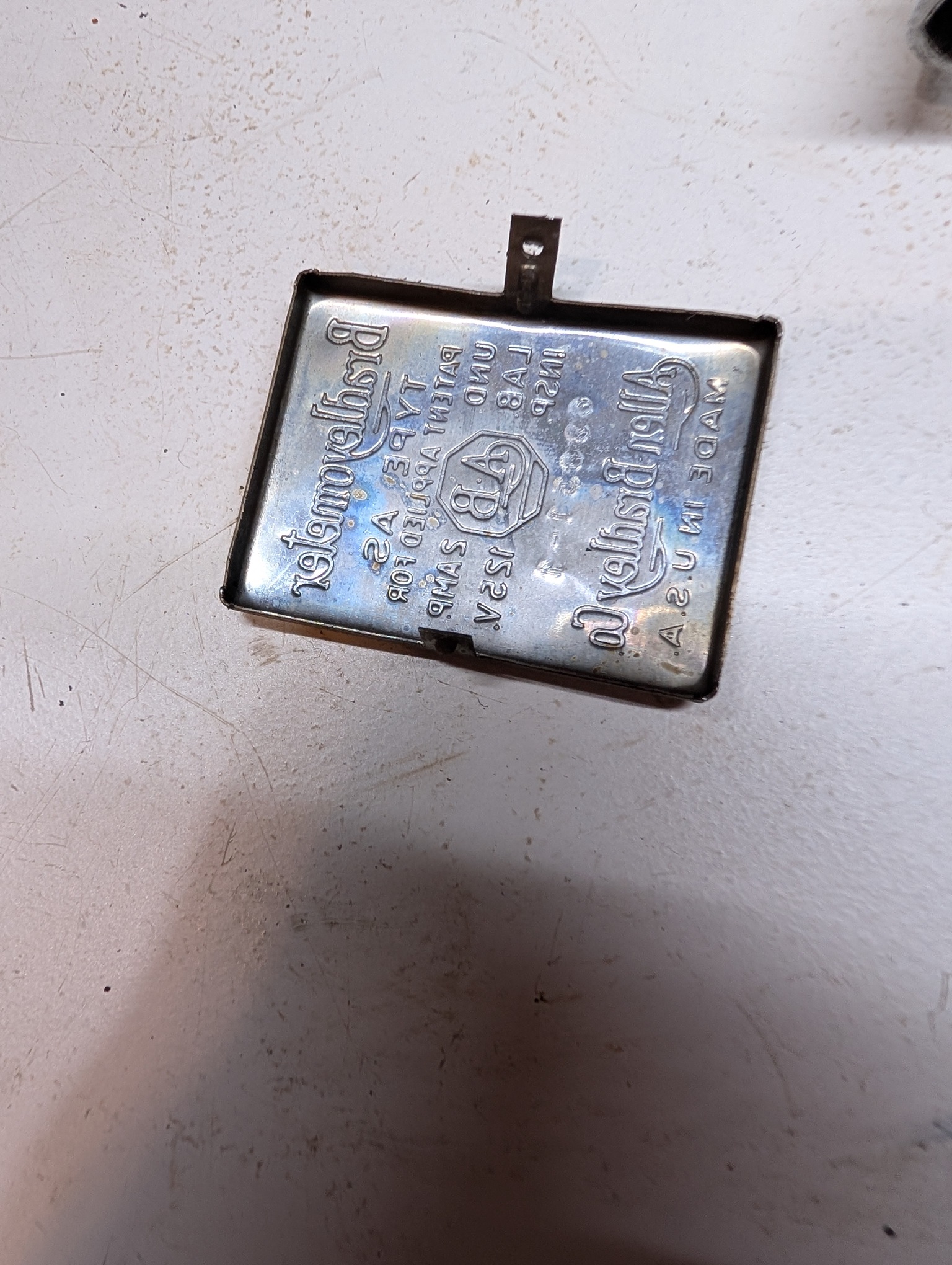
So this is the inside:
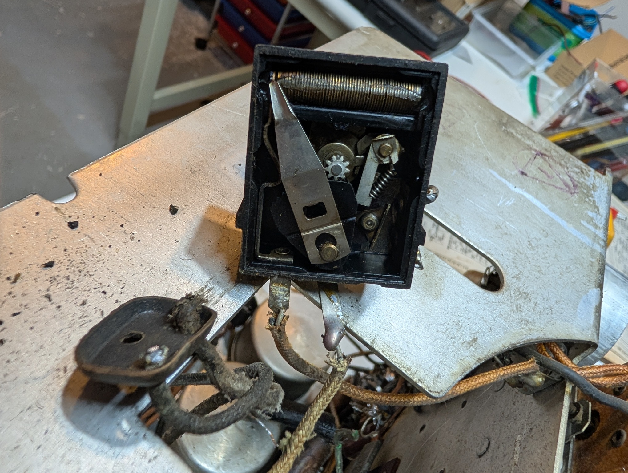
I put some F5 on the rheostat (the end of it then started making contact). The pot is wirewound and seems to be 3.7M or so, which is close to the declared.
Now the switch contact group was all black:
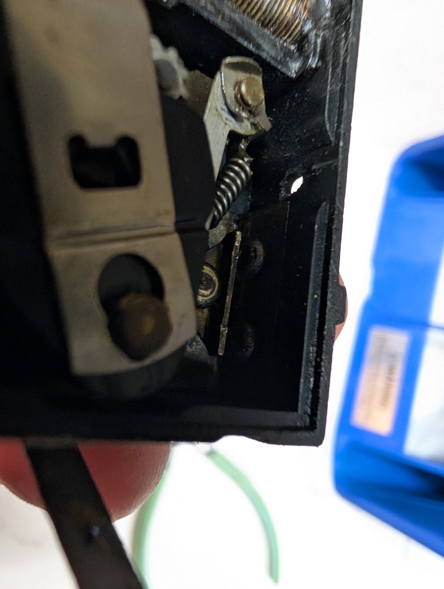
Some alcohol took care of the soot.
Also there was another problem: when the switch was made, the contact bar would sit above the actual contact bumps. The resistance then would be in a couple of hundred Ohms. The arm that holds it, it has some play and can land plus-minus 60 mils or so; I could push it down manually and this would make the made resistance better.
The arm is fairly soft, so I used fine pliers and bent it a little so it would land the bar a bit closer to the front pot's wall. This seemed to have improve the contact resistance.
I put some D5 on it for good measure.
I also put some F5 into the volume pot which seems to be a replacement type, judging by ribbed shaft. The shaft does not cover the bushing in full, and there is a sizeable opening there, so I sprayed F5 right in.
Then I put the tuning cap in.
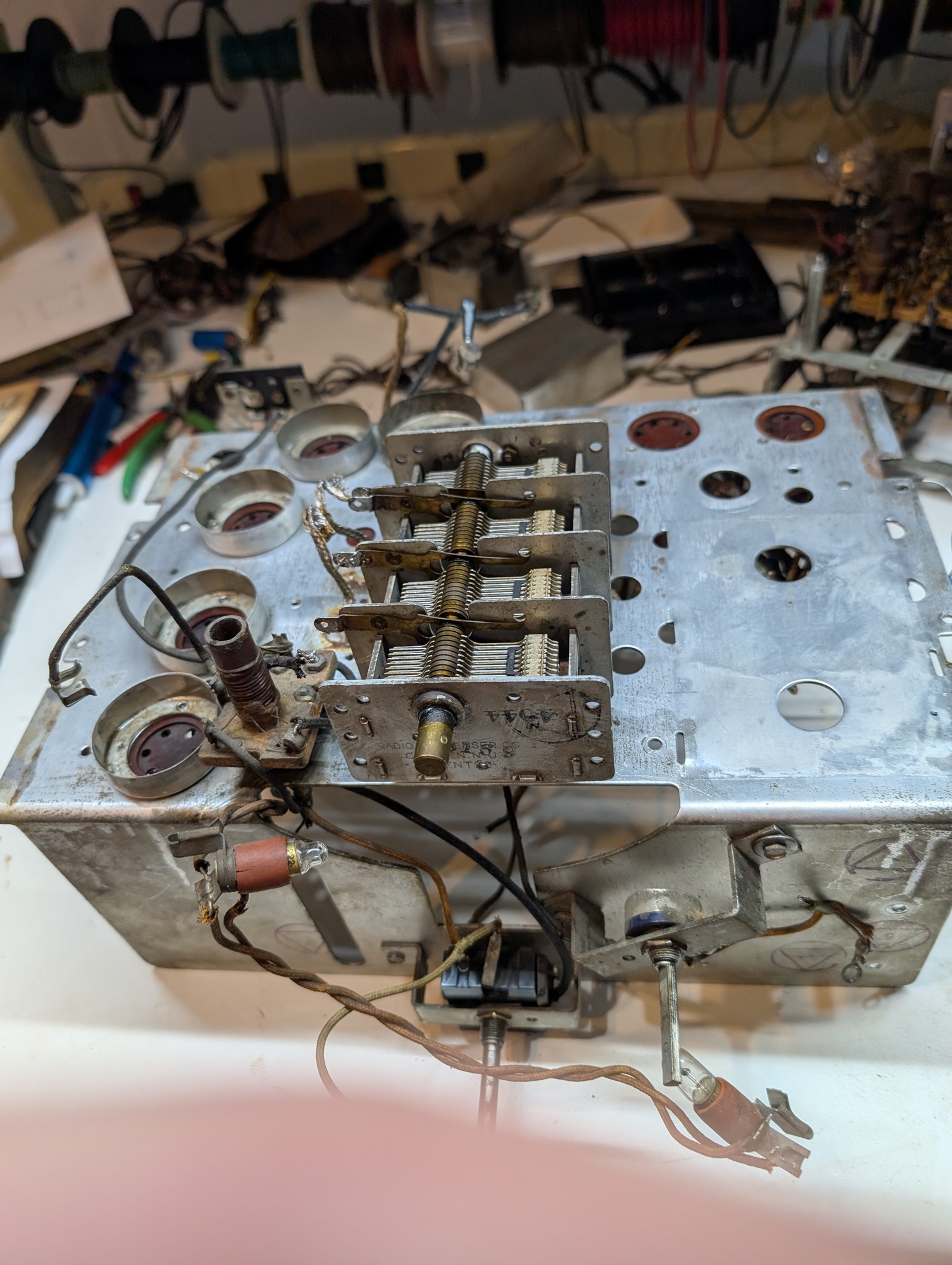
Should be enough for today, but maybe after dinner (petite sirloin) I don't get too drowsy, then I could do some more fun stuff.
People who do not drink, do not smoke, do not eat red meat will one day feel really stupid lying there and dying from nothing.
Posts: 18,427
Threads: 622
Joined: Oct 2011
City: Jackson
State, Province, Country: NJ
"И на старуху бывает проруха" (Russian saying).
Meaning: even a good marksman sometimes misses.
That sheer weight of the can should've alert me, but I guess, I got wrapped up...why hasn't no one stopped me.
That big can...it is the power transformer.
I have frozen it and pried some frozen tar aut of it.
Not sure this transformer is good, plus I cut the leads short.
Thinking what to do.
People who do not drink, do not smoke, do not eat red meat will one day feel really stupid lying there and dying from nothing.
Posts: 2,327
Threads: 23
Joined: Jul 2020
City: Greenlawn
State, Province, Country: NY
You may have to go the other way, Mike. Take a sample of the tar and determine what temperature the tar melts or at least gets soft. Hopefully not much above 212Deg F.
Heat till melting, with the can opening facing down. Drain as much tar as possible. With 2 pairs of "Channellock" pliers, grab the can toward the top and if possible, the core of the transformer through the opening at the bottom of the can, then work it out. If sufficient tar has been removed, at least you can splice the wires.
You likely know this but for the sake of others following the thread:
It appears that there are a lot of wires on this transformer. If the diagram is correct, the primary can be set for several voltages between 110(?) and 240(?) V. It appears that there are that there are 2 windings on the primary, each 120V, tapped for 110. In parallel, the transformer primary is set for 120. In series, 240. According to the diagram, each primary winding is 8 Ohm. The secondary is 200 Ohm. The Heater winding for all tubes except the rectifier is center tapped and should have the lowest resistance. The heater winding for the rectifier will also have a low resistance but is not the center tap.
Good luck.
The next lowest
"Do Justly, love Mercy and walk humbly with your God"- Micah 6:8
"Let us begin to do good"- St. Francis
Best Regards,
MrFixr55
Posts: 18,427
Threads: 622
Joined: Oct 2011
City: Jackson
State, Province, Country: NJ
Well, I am not sure I did not damage it.
I will test it, if it is in any shape to be tested.
Bummer...
People who do not drink, do not smoke, do not eat red meat will one day feel really stupid lying there and dying from nothing.
Posts: 18,427
Threads: 622
Joined: Oct 2011
City: Jackson
State, Province, Country: NJ
Found the exact data on the 9042, the transformer used in this radio.
5V / 2A, 640V / 133mA and 2.5V / 8.44A.
Cannot find the data on the A36, the one used in Superette R-7. I am yet to look at the mechanicals, but the only question electrically is the Hi-V winding.
People who do not drink, do not smoke, do not eat red meat will one day feel really stupid lying there and dying from nothing.
Posts: 5,654
Threads: 56
Joined: Sep 2008
City: Sandwick, BC, CA
Mike;
I doubt if the transformer was damaged by putting it in the freezer, but as long as you didn't bake it in the oven to melt the tar, or drive any screws into it yet.
Regards
Arran
Posts: 18,427
Threads: 622
Joined: Oct 2011
City: Jackson
State, Province, Country: NJ
No, nothing like it. Freezing and tapping.
The freezing was done for 1 day; the tapping was done using a block of some hardwood placed on the walls and whacked by a hammer, covering all area of each side (however many it took), and then the top of the case too.
Funny that when I placed the can upright and started whacking the top, the transformer slid don and stopped there. There is still some space.
Ten it occurred to me, I saw some copper strip soldered to the case coming from the transformer, so I suspect maybe this is what holds it.
People who do not drink, do not smoke, do not eat red meat will one day feel really stupid lying there and dying from nothing.
Posts: 5,654
Threads: 56
Joined: Sep 2008
City: Sandwick, BC, CA
That sounds like a connection for an electrostatic shield, RCA sets often had them, though I don't know if they had them in 1933. I suspect that RCA (along with G.E and Westinghouse) held patents on them as Philco and other makes seldom use them. I any event you will have to perform the same job you did to the power transformer in that A.K you restored a few years ago, but unlike the A.K I don't think there are terminals on the RCA's transformer so splicing to the remains of the old leads will be what you have to do.
Regards
Arran
Posts: 18,427
Threads: 622
Joined: Oct 2011
City: Jackson
State, Province, Country: NJ
I went to check the windings. At least by an Ohmmeter, they are OK.
Not sure what the best way to proceed is...half the tar is out, if not more.
This thing probably wants to be potted somehow. With something.
People who do not drink, do not smoke, do not eat red meat will one day feel really stupid lying there and dying from nothing.
Users browsing this thread: 5 Guest(s)
|
|
Recent Posts
|
|
Stromberg Carlson 1500 Squeal
|
| And life just keeps getting more complicated. By dconant.
Dittos'Jimradio — 08:01 AM |
|
Plug Voltages Needed For A 1943 CRV-20130 Power Supply
|
| That looks a lot like an aircraft connector of some kind, even if it's a U.S.N power supply. I have a book somewhere abo...Arran — 02:56 AM |
|
Plug Voltages Needed For A 1943 CRV-20130 Power Supply
|
| hello david,
I have a similar generator in my collection that features a cast iron, single-cylinder Briggs & Stratt...radiorich — 01:00 AM |
|
under chassis parts locator diagram for 1938 Zenith 9s262
|
| Has anyone gone to the trouble of creating an under chassis parts locator image? Yes, I can identify components by foll...bobloney — 08:57 PM |
|
Plug Voltages Needed For A 1943 CRV-20130 Power Supply
|
| Try looking at this site the book mark is for a old generator that I was given. David https://radionerds.com/index.ph...David — 08:36 PM |
|
Plug Voltages Needed For A 1943 CRV-20130 Power Supply
|
| Hello Everyone,
I am looking for voltage identification for all the pin positions on the socket of a CRV-20130 power su...Tonym4704 — 08:16 PM |
|
Philco P45-6365 Universal Transformer Instruction Manual
|
| Can anyone guide me to where this may be found?GRG — 03:00 PM |
|
54C Complete Teardown/Rebuild
|
| I don't think that I have encountered a 12Z3 before, curious how it uses one of those but includes a #43, which is a 25 ...Arran — 02:17 PM |
|
HiFi (Chifi) tube amp build - but my own design.
|
| It's the other forum. I'm also in DIY, but mostly read there. Honestly, I kinda jumped into this without much thought to...TV MAN — 10:43 AM |
|
Philco 71 Code 125
|
| Hello,
I am in need of a schematic for this radio. Mine has the three separate circular tube shields and a shadow me...dconant — 08:06 AM |
|
Who's Online
|
There are currently 1965 online users. [Complete List]
» 1 Member(s) | 1964 Guest(s)
|
|
|

|
 
|








