Posts: 9
Threads: 2
Joined: Jul 2026
City: Schodack Landing
State, Province, Country: New York
Hello All ,
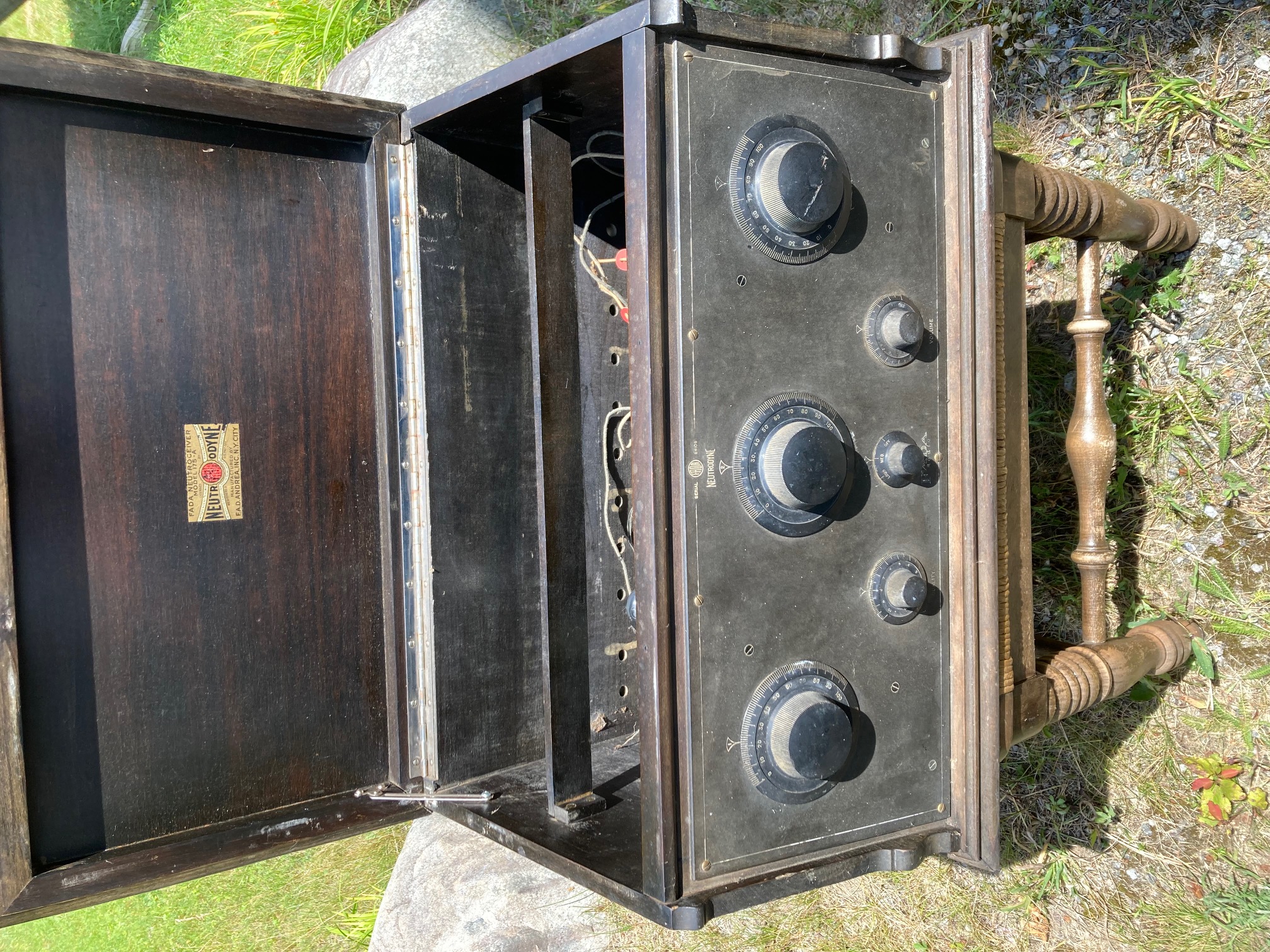
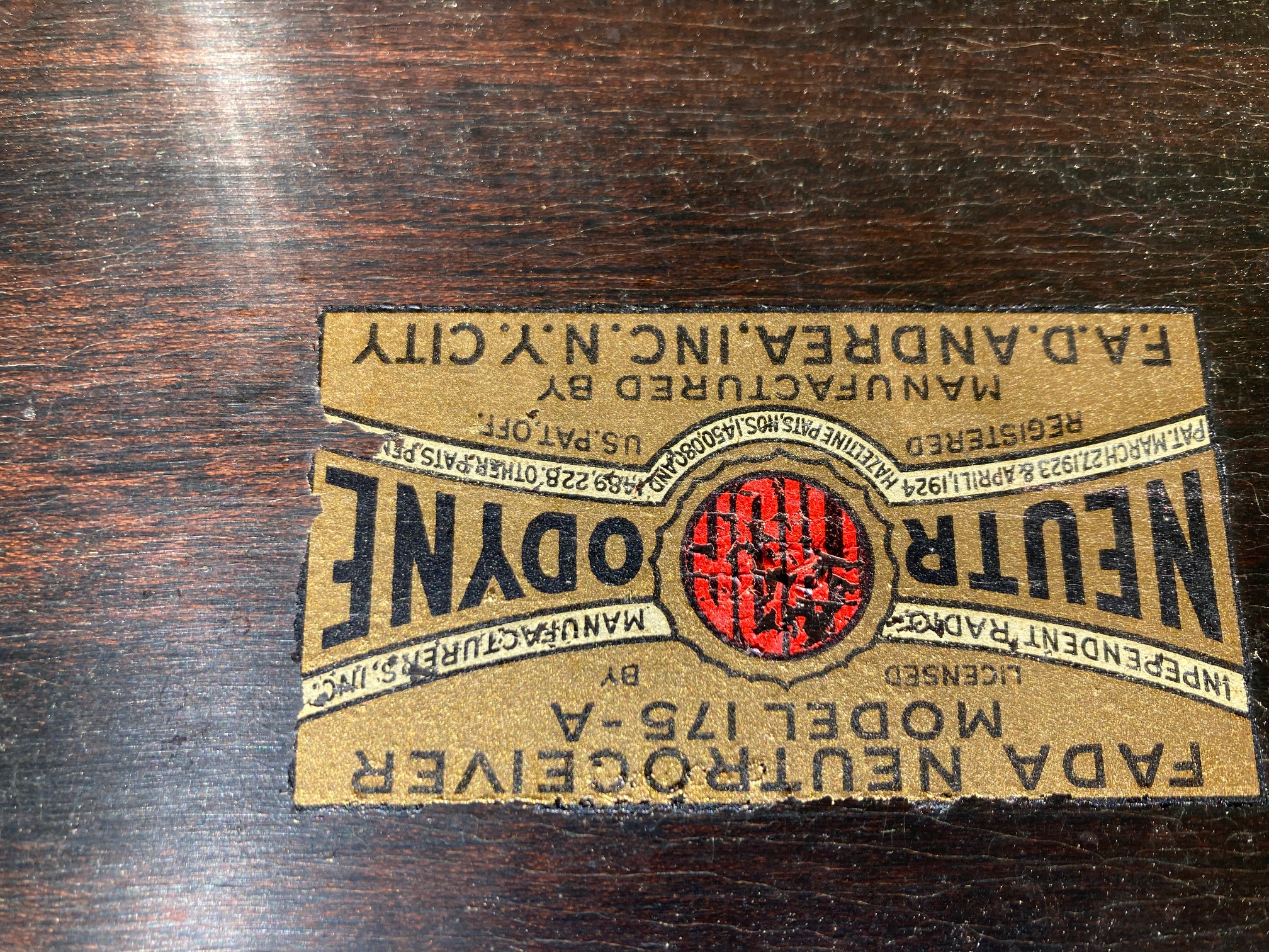
New member here, just acquired a Fada 175 at a flea market, looks very clean, missing a couple tubes, so took a chance for $10.
I am an FCC licensed electronics tech by trade, i remember that first FCC test, it was all tube theory !!
which of course they no longer taught at college in 1975,
enough background,
i have already located a schematic from Wm Bunting site, however this does not show tube #'s
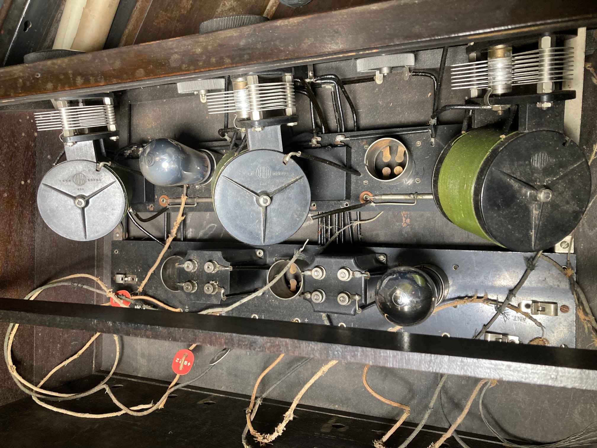
My unit has 5 tube sockets and i am missing 3 tubes, i do have 2- CX-301A tubes, but will probably order a full compliment of new tubes,
interestingly there are 3 lead tube caps ? maybe common for the era ?
so i guess my first challenge is finding tubes and building a power supply or battery bank
Wish me luck
RG
RG
Imagine if AI, was Actual Intelligence
Posts: 1,422
Threads: 41
Joined: Jan 2014
City: Wellborn Florida
(This post was last modified: 07-22-2026, 03:41 PM by David.)
Posts: 9
Threads: 2
Joined: Jul 2026
City: Schodack Landing
State, Province, Country: New York
Thanks will take a look
RG
Imagine if AI, was Actual Intelligence
Posts: 2,327
Threads: 23
Joined: Jul 2020
City: Greenlawn
State, Province, Country: NY
Hi RG,
It's Deja Vu all over again. I thought that I posted a reply to you, but I can't find it, so here goes again. Forgive me if you already saw my post, but I am adding some new info, so it maty be worthwhile to read this post.
The set uses the "01" or "01A" triode for all positions except for the detector which should be a "00" or "00A". The difference is that the following:
00 and 01 tubes had 5V 1A bright tungsten filaments. 00A and 01A have 5V 1/4A dim thoriated tungsten filaments.
RCA tubes were referred to UV201s if the pins were short and the base was the "navy" base, or UX201s if they had the long pins for plug in sockets However, UX 201s will fit the same sockets used for UV201s. Cunningham tubes are referred to as C301, C300 C301A or C300A. However, both RCA and Cunningham tubes were built by RCA- actually, built by GE or Westinghouse and are the same, no matter if they were RCA branded or Cunningham branded. (RCA held the patents and provided worldwide radiotelephone service, radio equipment sales and service, and managed broadcasting through the NBC Radio Networks. GE and Westinghouse manufactured the receivers, transmitters and tubes. RCA themselves did not have manufacturing facilities until they bought GE's Harrison Tube Works and the Victor Talking Machine company.)
The "Grid Leak" triode detector with or without regeneration was the common detector used in radios from about 1920 to about 1929 when the "Biased" triode detector became popular. Diode detectors did not become popular until about 1933 and the introduction of the 55, 75, 2B7, 6Q7 dual diode-triode detector / 1st AF amp tube.
Attached are links to the 1932 and 1940 versions of the RCA Receiving Tube Manuals from World Radio History website. There are great descriptions of these tubes and the circuits involved:
SplitPDF
RCA-Receiving-Tube-Manual-1940-RC-14-OCR.pdf
Unfortunately, I cannot find any diagram for the FADA 175-A. The one from the Nostalgia Air collection of Rider's service documents shows an entirely different 8 tube AC-DC set ca late 1930s.
Here is a video of the repair of a 175A
Repair of FADA 175A 1924 RADIO
Here is the Rider schematic of the FADA 140 which I own, and the FADA 170A and 192 series radios.
The 160 and 175A Schematics do not show the detector's grid leak condenser and resistor, but the 192 schematic does. Schematics here:
Hope this helps.
The 00 and 00A were "soft" tubes to which a small amount of gas (usually argon, I believe) was added to the tube. This made it a poor amplifier, but made it a rather sensitive "Grid Leak" detector. )11s and 01As were referred as "hard" tubes, evacuated to a very high vacuum while the components were inductively heated, then a "getter" was flashed. The getter is a coating inside the tube meant to react with any O2 left in the tube.
Good 00s or 00As are not too easy to find. Theoretically, a 01A or a 112A should work as a detector. However, use 45V as the detector plate voltage if using a 01A or 112A as a detector. If you have a good 00A, then the plate voltage of 00 or 00A tubes is 22V.
"Do Justly, love Mercy and walk humbly with your God"- Micah 6:8
"Let us begin to do good"- St. Francis
Best Regards,
MrFixr55
Posts: 9
Threads: 2
Joined: Jul 2026
City: Schodack Landing
State, Province, Country: New York
Fixr55
Thank You so much for the info,
Mine is clearly labelled 90v & 22v, so the original must have been a 00
if i use an 01, you're saying increase it to 45v
can i pick your brain a little more
also have 3, what appear to be tube covers, lead w spring tabs, maybe common for the era ?
i do see other restored units operating without them.
i seriously doubt i'm looking for an 8 ohm speaker. as plate voltage for audio section is 90 and it appears to pass thru the "horn" winding.
Have seen some old phonograph horns and some old RCA enclosures, for sale, various on-line sources.
looks like i'm already in the rabbit hole, just figuring out what i need to give it a test.
certainly not there yet, need to go back to home page and find a list of reputable sources,
Thanks again
RG
Imagine if AI, was Actual Intelligence
Posts: 2,327
Threads: 23
Joined: Jul 2020
City: Greenlawn
State, Province, Country: NY
Hi RadioGuy56
First off, you are welcome!
Secondly, you could either use the speaker and output transformer out of an "AA5" AC-DC radio the used a 50L6, 50B5 or 50C5 (or any 25V or 35V variant of these tubes). The output transformer primary impedance is usually about 2.5KOhm. It won;t be loud but you could hear something.
The first radios used headphones, usually having an impedance between 1KOhm and 2KOhm. You can find decent headphones on the various auction sites (example eBay) starting at around $25-$50. I Make sure that they are at least 1KOhm. Horn speakers, using the same magnet, coil and diaphragm setup as a headphone, and also having an impedance of between 1KOhm and 2KOhm were developed. Horn speakers are available on the various auction sites but working horns in good condition tend to start at least $150 and can extend to $300 or more for Atwater Kent, Amplion or Burns, especially if they have wood or tortoiseshell horns. Cone speakers came around in about 1924-1925. Cone speakers were driven by an electromagnetic "reed, suspended in the field of a horseshoe magnet. These also had impedances of between 1K)hm and 2KOhm, but commonly were used with more powerful output tubes such as the 112A or 71A, which required a C battery to provide sufficient negative grid bias.
Thirdly, this set is similar to many other sets of the era such as the Atwater Kent Model 10, except it employs the "Neutrodyne" principle to prevent the RF amplifier stages from going into oscillation. RCA owned the patents for the super-regenerative detector and the Superheterodyne principle but did not own the patents for the Neutrodyne circuit or for AVC (Automatic Volume Control) which were held by Hazeltine Corporation (of my hometown Greenlawn, NY, about 1.5 mile from me). Don't worry about adjusting the neutralizing condensers yet; in fact, try not to disturb them. These are the wire within a tube type device behind the 2 tube sockets between the RF coils on your set.
Fourthly, the lead caps are supposed to prevent feedback or oscillation. Not sure how that works when they cover only the top of the tube. if the spring is on the outside surface and extends from a hole in the middle of the cap it is because they were designed when tubes had a tip like the miniature tubes (12AX7, 50C5, etc.). I am not sure if they help, especially with this set, and may negatively affect this set if the set was "neutralized" without them.
Now, how to tackle this unit without spending your life savings.
First off, ohm the 2 Audio transformers. These are the black boxes on the rear row of tube sockets. The primaries are usually about 1KOhm or so and the secondaries are about 4KOhm or so. Do not be surprised to find either the primary or secondary, or both to be open. Modern transformers like the P-T156 transformer from Amplified Parts (Formally Antique Radio Supply) will suffice as replacements and are relatively inexpensive.
01A tubes are plentiful on auction sites. The most expensive versions are the "BBT" (Brass base and Tipped) versions from 1921-1923 or so, which match the age of your radio. However, the phenolic based "S" envelope versions without the tip (look like a 15Watt light bulb) are fine. Amazingly, many of these 100 year old tubes still work. If you are looking for reliability more than for the correct period, the "ST" ("Sholder Tube" or Coke bottle shaped) tubes are the latest versions and likely have the least amount of hours on them. They may also be the least expensive because production of radios using 00 and 01 series tubes stopped around 1927-1928. Shoulder Tubes were introduced around 1933, making these tubes definite replacement tubes and not OEM. Considering that these radios were likely put into storage shortly after ST type tubes were installed make them a good bet IMHO. Expect to pay be$15-$25 per tube. You can plae a "Wanted to Buy" ad in the Phorum in the "Wanted" section of the Trading Post on the Phorum. Go to the home page and scroll down to the bottom and you will find the link.
The RF coils and tuning capacitors are likely good unless the primary of the first RF coil was blown from a lightning hit. Not to worry, if you have a very strong AM station, connecting a wire to the primary of the detector coil will likely allow signal to be detected.
I may have stated previously that you can use a 6V source or even the 5V output of an old computer power supply and 10 9V batteries to power the set for now. If you find yourself collecting more of these early battery sets, consider buying either a kit or fully assembled power supply. or building one from one of the many schematics and plans for these that can be found on the 'net. You can find these on e-bay for as little as $75 for a kit. The "gold standard" power supply for these radios is the ARBE III. Available from A tique Radios LLC (arbeiii.com) Unfortunately, the price of these have increased to $225 plus tax and shipping, but I am very happy with mine.
The 00A and 01A are both covered in some detail on the 1932 version of the RCA Receiving Tube Manual that I provided the link to in my previous post. Let me know if you have difficulty downloading and saving that manual to your computer. Download the 1940 version also, but use the 1932 version for this project.
Good luck and keep posting!!
"Do Justly, love Mercy and walk humbly with your God"- Micah 6:8
"Let us begin to do good"- St. Francis
Best Regards,
MrFixr55
Posts: 5,654
Threads: 56
Joined: Sep 2008
City: Sandwick, BC, CA
I suspect that the metal caps were for the domes of the audio tubes in this set in an attempt to reduce microphonics, which was a common problem with "globe" or "balloon" envelope tubes had less physical support for the internal structure. This was one of the reasons the tube manufacturers adopted the S.T or "Shouldered Type" envelopes in the mid 1930s, and later the G.T or "Glass Tubular" style envelopes, something many audiophools can't fathom.
The speakers these sets used were high impedance, so you will need an audio output transformer to use one with a more modern 4 or 8 ohm speaker, otherwise a set of headphones, a horn, or magnetic cone speaker from the era will work with the set. The advice I read online is NOT to try operating one of these sets on a horn speaker with a 171A in the final output socket as it can damage the the driver, but using one with a later cone speaker should be fine, otherwise use a 01A or a 112A with the horn.
Regards
Arran
Posts: 9
Threads: 2
Joined: Jul 2026
City: Schodack Landing
State, Province, Country: New York
Fixr55, Once again huge thanks, lots of good info..
Arran, hello, an old thread of yours, showed up in my initial research on the 175,
which in turn brought me here. i had heard or read that horns/ speakers of the era were high impedance.
so my first thought was to identify what i dont have, missing tubes , horn or speaker, loop antenna.
then move onto initial troubleshooting, checking transformers and coils, pulling chassis from cabinet for a better look
& sourcing batteries or power supply.
i'm sure it will be a challenge
RG
Imagine if AI, was Actual Intelligence
Posts: 2,327
Threads: 23
Joined: Jul 2020
City: Greenlawn
State, Province, Country: NY
Yes, the horn and magnetic cone speakers are high impedance, between 1kohm and 2kohm. A speaker AND output transformer from a 1940s - 1960s 5 tube AC DC radio will work, but the sound output with an 01a will be low. If there is provision for C- grid bias for the audio tubes, consider buying a112A. If you find that the 01A sounds better as an output tube than the 112, you can use the 112as a detector.
Believe it or not, these radios are actually very simple. You WILL get this to work. We will be happy to help!
"Do Justly, love Mercy and walk humbly with your God"- Micah 6:8
"Let us begin to do good"- St. Francis
Best Regards,
MrFixr55
Posts: 5,654
Threads: 56
Joined: Sep 2008
City: Sandwick, BC, CA
R.G;
These sets would have used a long wire antenna, I think there were some loop antennas available in the aftermarket, but unlike a 1940s era AC/DC set they were never integral to the front end of the radio. Sets with Neutrodyne circuits are a sort of improved TRF design where they have an extra winding that feeds a small amount of negative feedback to the input of each RF amp circuit preventing oscillation, so they have a higher gain then a straight three dialed TRF set, that was until they introduced screen grid tubes in the late 1920s. It's basically to neutralize any positive feedback that can cause the circuit to go into oscillation, before that they had to use a bypass condenser or reduce the gain of the circuit.
I would like to get my FADA going again someday, the only part missing is the cabinet, and one of the audio transformers is open. To this day I'm not sure whether it was a 175A or some other model, or whether it was a table set, or was pulled out of a console model. However I am reasonably certain that it was sold in Canada as it has a set of mid 1920s Canadian Westinghouse branded tubes, with Bakelite bases.
Brass based tubes were not around for long, likely due to cost, and I suspect that most of those produced were 201s not 201As, 201s had 1 amp filaments and were hard on A batteries. If you can't find 201As 6C4s can be used as a substitutes, for testing purposes, or if you like making adapters. The biggest issue with 201as, as with any other early tube, is that the solder in the pins often goes bad, so if you have a weak 201A, or one with an open filament, try sucking the old solder out and resoldering the pins, they don't usually fail unless abused.
Regards
Arran
Posts: 9
Threads: 2
Joined: Jul 2026
City: Schodack Landing
State, Province, Country: New York
Arran,
I cant say thanks ! enough to you guys, you are a wealth of knowledge.
i see a bunch of Radiola style speakers out there, price $50 and up. Some look beat up ragged.
some actually pretty good ?? i will post wants in the phorum first, should be a more reliable place to start.
will be enjoying the lake and sunshine before rain moves in later in week, but that gives me an opportunity
to pull the chassis and put this in the bench. it looks like the chassis will pull out thru front of cabinet.
it'll be a couple days but stay "tuned"
RG
RG
Imagine if AI, was Actual Intelligence
Posts: 9
Threads: 2
Joined: Jul 2026
City: Schodack Landing
State, Province, Country: New York
Hello,
just a quick update,
after a couple hours of workbench cleanup and re-org, managed to put the chassis on my work bench.
after some pre-lim continuity checks, which showed tuning coils and inter stage transformers to be "ok "
took a 12 volt battery (from an old ups i have) and used it to prove voltage to various circuits.
was able to prove filament and plate voltage to all tube sockets.
will admit was puzzled for a hot minute as to why no voltage to final audio tube !!!
studied schematic thinking had something to do with: on-off -Vol switch.
Then realized plate voltage for final amplifier passes thru voice coil of horn /speaker.
Coil is not shown on schematic / just a terminal labelled horn, (which is still MIA.)
So the chassis appears pretty solid, maybe redo, a couple solder joints.
finally have a line on some tubes and also a couple speakers that look promising.
RG
RG
Imagine if AI, was Actual Intelligence
Users browsing this thread: 1 Guest(s)
|
|
Recent Posts
|
|
Stromberg Carlson 1500 Squeal
|
| Hello Rob,
I agree with you—I have one here at my house that I need to check out. It’s way over-engineered just to make...radiorich — 11:05 AM |
|
My Atwater Kent 84
|
| Well getting around to restoring my AK84. Mike was a big part in me being able to snatch this one a few years ago. I won...462ron — 10:57 AM |
|
Plug Voltages Needed For A 1943 CRV-20130 Power Supply
|
| The engine is a B&S 23 inch cast Iron holds 2 quarts of oil. The Generator is a 4 pole 1800 rpm mine was made in 195...David — 10:51 AM |
|
Philco 45-6365 Universal IFT Instruction Manual
|
| Dale: Modified topic as suggested. It is not for a specific project. I found it in a box of stuff I recently purchased...GRG — 10:34 AM |
|
Plug Voltages Needed For A 1943 CRV-20130 Power Supply
|
|
That looks a lot like an aircraft connector of some kind ...
That is a MIL-5015 style connector, used in a wide v...DaleHCook — 10:19 AM |
|
Philco P45-6365 Universal Transformer Instruction Manual
|
| I would suggest changing the topic from "P45-6365 Universal Transformer" to "45-6365 Universal IFT."...DaleHCook — 10:08 AM |
|
Stromberg Carlson 1500 Squeal
|
| And life just keeps getting more complicated. By dconant.
Dittos'Jimradio — 08:01 AM |
|
Plug Voltages Needed For A 1943 CRV-20130 Power Supply
|
| That looks a lot like an aircraft connector of some kind, even if it's a U.S.N power supply. I have a book somewhere abo...Arran — 02:56 AM |
|
Plug Voltages Needed For A 1943 CRV-20130 Power Supply
|
| hello david,
I have a similar generator in my collection that features a cast iron, single-cylinder Briggs & Stratt...radiorich — 01:00 AM |
|
under chassis parts locator diagram for 1938 Zenith 9s262
|
| Has anyone gone to the trouble of creating an under chassis parts locator image? Yes, I can identify components by foll...bobloney — 08:57 PM |
|
Who's Online
|
There are currently 1201 online users. [Complete List]
» 3 Member(s) | 1198 Guest(s)
|
|
|

|
 
|








