Posts: 1,369
Threads: 94
Joined: Jan 2014
City: Annapolis, IL
State, Province, Country: USA
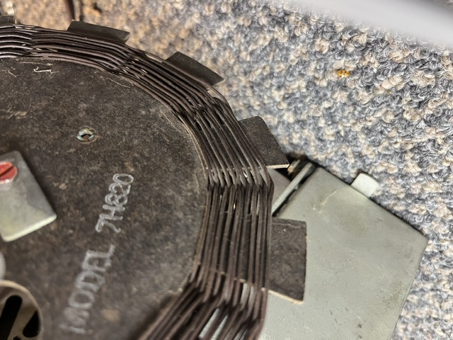
I don't think I posted about this one, so it's (hopefully) near the final of the resto. I read where Mike (Morzh) did one or very similar. I have the recap done, had to replace the dial light socket since the original came from togetherness. I used a candelabra socket from a local home store and managed to get it into position without any mods to the chassis or cabinet. I've cleaned controls and tube sockets, and have it playing pretty good. I do feel an alignment would bring it in even better, but haven't done it yet, so it's on my list. I think I saw where Morzh had some alignment issues but not sure what he did to clear it up. In his YouTube video, his sounded just like mine. Clear but yet kinda fuzzy and the dial tracking is off. I had planned to throw a 10.7 mhz signal through and adjust for best waveform, then set the discriminator to balance. It's "almost" good enough as it is, but I feel this radio is much more capable, and it DOES have a very good sound! Below are a few pics of my work. Nope, I didn't restuff, but I don't think the radio will really care.
EDIT: I did replace the selenium rectifier with a single diode and didn't do anything else. At 120v input I get 129v on the B+. Just a FYI.
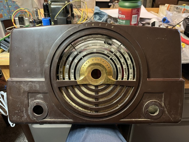
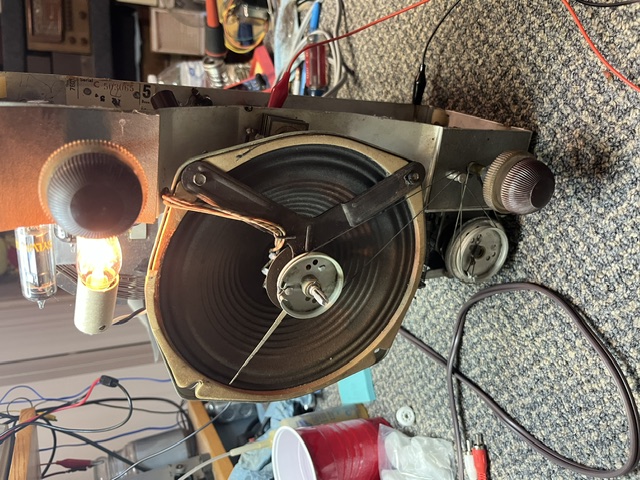
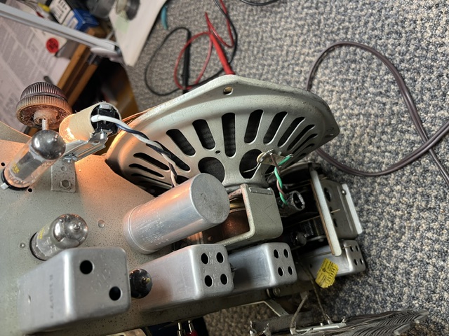
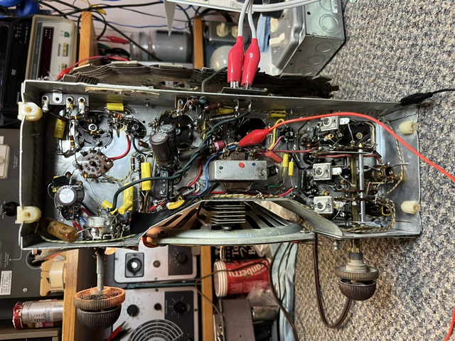
If I could find the place called "Somewhere", I could find "Anything" 
Tim
Jesus cried out and said, "Whoever believes in me , believes not in me but in him who sent me" John 12:44
(This post was last modified: 07-11-2026, 11:31 PM by TV MAN.)
Posts: 348
Threads: 20
Joined: Nov 2016
City: Cromwell
State, Province, Country: CT
Your radio is looking good! I love this vintage of Zenith sets as they have an RF amp and 2 IF stages for all bands. They are just good sounding and sensitive sets.
Tony
“People may not remember how fast you did a job, but they will remember how well you did it”
Posts: 1,136
Threads: 55
Joined: Feb 2013
City: Shenandoah,
State, Province, Country: Pennsylvania
Tim, I have the similar radio, only 1 FM band so otherwise the same set. I also replaced the selenium rectifier with a silicon diode and nothing else. The few extra volts of B+ I figure didn’t hurt anything and it’s been playing for nearly 2 years just fine. This is a good performing set with plenty of volume and sounds great with the 8” speaker. I’ve modified my Eico sweep generator and bought a 10.7 MHz crystal for it to have a rock steady signal for IF alignment. Also bought a 9.1 MHz crystal for doing certain Philco FM sets. Love this set!
Ron
Bendix 0626. RCA T64 Philco 20B
Philco 41-250. Philco49-500
GE 201. Philco 39-25
Motorola 61X13. Philco 46-420 Crosley 52TQ
Philco 37-116. Philco 70
AK 35 Philco 46-350
Philco 620B. Zenith Transoceanic B-600
Philco 60B. Majestic 50
Philco 52-944. AK 84
Posts: 3,189
Threads: 226
Joined: May 2008
City: Omak
State, Province, Country: WA
Hello Tim,
I also have that set and plan to restore it this winter. The biggest issue with mine is a small crack, less than an inch long, on one of the back corners near the bottom of the Bakelite case. I’ll repair it from the inside so no one but me will ever know—it barely even shows.
That is Good to hear Tim and ED about replaceing the selenium rectifier with a silicon diode and Tim, my power here is maybe a volt or two higher at times and I will used 200 -250 volt rated electrolytic capacitors in it or higher .
Sincerely Richard
Posts: 5,654
Threads: 56
Joined: Sep 2008
City: Sandwick, BC, CA
Tim;
I heard in one or more shango066 videos, where he was repairing early FM sets, that the manufacturers would add an extra cap in the audio output circuits that would make many of these sets sound sort of "muddy" and by clipping it out the fidelity would improve. It's sort of a mystery as to why they were added. maybe they thought that prospective buyers of FM sets wouldn't like them if FM didn't sound like AM broadcast?
Regards
Arran
Posts: 1,369
Threads: 94
Joined: Jan 2014
City: Annapolis, IL
State, Province, Country: USA
Hmmm, that's interesting Aran. I saw when Morzh redid one that there was a capacitor that had a grounded shield, I believe it was to the volume control. I don't recall mine having that, just a regular cap. I wonder if that cap for tone is that 1200v? cap across the transformer primary or something. I didn't really notice any overly high B+ with the diode replacement either, in fact, this radio seems to like higher B+ /line voltage. It plays much better. Go much under 100v ac and it wont hardly play. I might need to retest the tubes and check for a weakie. Our ac usually runs 120-123v. Pretty much within the high limits. Used to be about 127v and had to use an isolation transformer on my Dyna amps or it would blow filter cap cans.
If I could find the place called "Somewhere", I could find "Anything"
Tim
Jesus cried out and said, "Whoever believes in me , believes not in me but in him who sent me" John 12:44
Posts: 1,620
Threads: 53
Joined: Nov 2017
City: Menlo Park
State, Province, Country: CA
I restored a similar set last year, but a different model with separate IFTs for FM and AM. They all had silver Mica disease, but could be repaired. Hope you don't run into those troubles.
I am always a bit fascinated by sets that have the 44MHz band I FM, just because it is a somewhat obscure historic artifact.
I don't hold with furniture that talks.
Posts: 1,369
Threads: 94
Joined: Jan 2014
City: Annapolis, IL
State, Province, Country: USA
Ed, I found that 2nd FM band to be quite interesting myself. I didn't even know it existed. I read through your thread and we are running into similar issues and fixes. So far ... I haven't heard any evidence of SMD, but, that doesn't mean it's not there playing with me. I found a Shango video where he was talking about a cap right off the detector that limits the highs at low volume settings, but his was a newer radio. I did get a TinySA, but haven't gotten it completly figured out yet. I too had to replace some bad wiring. I haven't attempted an alignment yet, but its next on the list unless SMD is present. I've also heard mica caps get noisy, even new ones. Ran into that into an amp build I did awhile back.
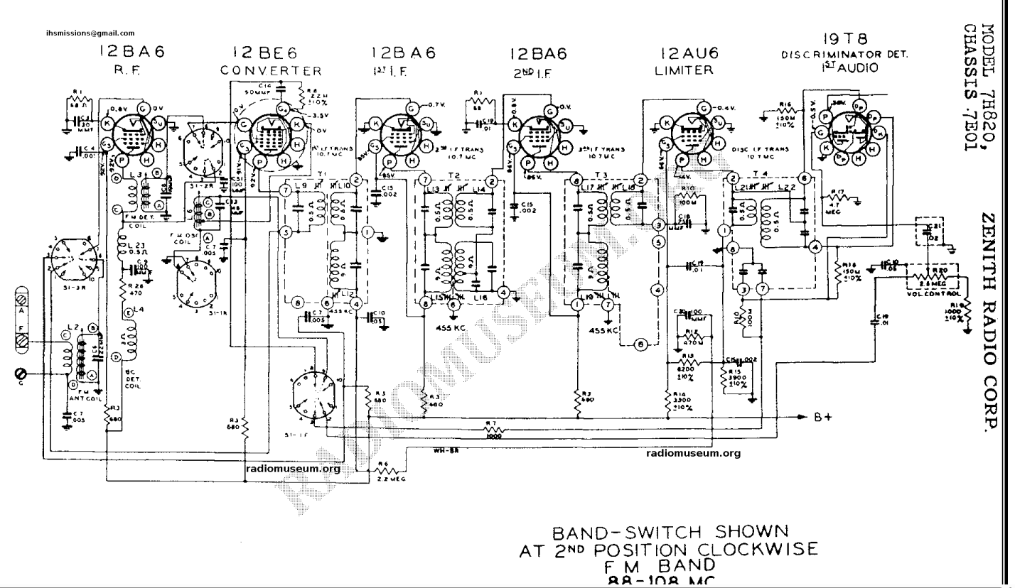
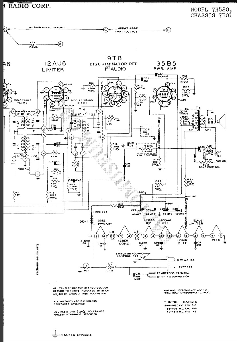
Here's the schematic. It is from Radio Museum, so it's in 2 parts. I think the cap Shango is talking about might be C19, but it goes to the band switch, and looks like if I clip it, then one end of the volume control is floating. May be a non issue - unless it's something to di with the AVC. I did notice that the AVC seems a little weird, meaning that some stations are much louder than others, so I may need to take a closer look. This one shows a shielded cap going to the volume control like Mikes (Morzh) on the schemo, but I don't remember finding that in my set. It looked original when I started. I even went through the paper caps I removed and double checked and didn't find it, so this radio might not have it. Anyway, I have the alignment information, but may have to do it like Mr. Carlson and inject a 10.7 mhz signal and take voltage readings at the detector transformer.
If I could find the place called "Somewhere", I could find "Anything"
Tim
Jesus cried out and said, "Whoever believes in me , believes not in me but in him who sent me" John 12:44
Posts: 1,222
Threads: 50
Joined: Oct 2017
City: Allendale, MI
I have the same radio and it has been performing beautifully. I use it in the bedroom and have been known to broadcast rain sounds on my FM transmitter listening to it on this radio. Helps me sleep! The radio will sometimes be on for 12 hour stretches.
Posts: 434
Threads: 9
Joined: Apr 2023
City: Roanoke
State, Province, Country: Virginia
EdHolland Wrote: I am always a bit fascinated by sets that have the 44MHz band I FM, just because it is a somewhat obscure historic artifact.
I own a Philco 42-355 with Major Armstrong's FM band. It is my only antique radio with FM. My military SG-3U AN/URM-70 FM signal generator is my source for listening to it. It sounds very good when using the external modulation input. Although the lowest frequency for the SG-3U is specified at 50 MHz, it tunes a little below that so I can easily use it at the top end of the old FM band. As a semi-retired broadcast engineer I have a couple of FM processors which provide pre-emphasis. The old band used the same 75 kHz deviation and 75 us pre-emphasis as the current FM band.
Dale H. Cook, GR/HP/Tek Collector, Roanoke/Lynchburg, VA
https://plymouthcolony.net/starcity/radios/
Posts: 1,136
Threads: 55
Joined: Feb 2013
City: Shenandoah,
State, Province, Country: Pennsylvania
Tim, I don’t like how Zenith draws their schematics using tube base drawings the way they do, I go cross-eyed trying to unscramble it, so I sprang for a Sam’s Photofact for it, makes it so much easier to read! Sam’s does a great job of clearing up schematics.
Ron
Bendix 0626. RCA T64 Philco 20B
Philco 41-250. Philco49-500
GE 201. Philco 39-25
Motorola 61X13. Philco 46-420 Crosley 52TQ
Philco 37-116. Philco 70
AK 35 Philco 46-350
Philco 620B. Zenith Transoceanic B-600
Philco 60B. Majestic 50
Philco 52-944. AK 84
(This post was last modified: 07-26-2026, 08:14 AM by 462ron.)
Posts: 2,327
Threads: 23
Joined: Jul 2020
City: Greenlawn
State, Province, Country: NY
I have the same 3 band set, unrestored and fully functional. The electrolytic caps and selenium rectifier are original and functional. I do have to pull this one apart, and recap as I thought, based on a slightly newer one that since that one had ceramic disc caps that this one dod also. Now that I have seen your pix, I need to check this out further.
WARNING!!! These are true HOT Chassis sets, and, of course, are made more dangerous by the switch being on the chassis leg of the power line, creating a condition that depending on the plug polarity and switch open or closed will ALWAYS leave a condition one way or the other where the set could be unsafe on the bench or with knobs missing. For example, if the plug is oriented with the chassis at neutral potential with the switch closed the chassis is safe, but then with the switch open, the chassis becomes hot due to the tube heaters resistance which is much lower when the tubes are cold. With the plug reversed, the chassis is cold when the switch is open because the tube string is at neutral potential, but with the switch closed, the chassis is hot. I always rewire these sets so that neutral pin connects to the chassis and the switch is on the hot side. See the following article from Philip Nelson's "Phil's Old Radios" (antiqueradio.org) ©1995-2025 Philip I. Nelson, all rights reserved:
https://antiqueradio.org/safety.htm
Note that all AC-DC AM-FM radios I have worked on are "HOT" chassis (power line connects to chassis through the power switch) as opposed to "Warm" chassis (chassis connected to power through a cap or cap and resistor to limit current at line frequency but to allow conduction at radio frequencies).
One of the keys to how nice this set sounds is the 8" speaker. It sounds almost as good as my RCA 1R91 Livingston, whose 250V and 6V6 SE output and rather large OPT gives that radio its characteristic sound. That set is restored.
Edwin Armstrong Is responsible for many major inventions in radio, including the regenerative and super-regenerative detectors, licensed to Westinghouse and RCA, the Superheterodyne receiver, licensed to Westinghouse and RCA and several FM radio patents as well as patents in radar. However, patent wars arose between him, De Forest and GE engineers for the Regenerative patent and Frenchman Lucien Levy for the Superheterodyne patent cost Armstrong both emotionally and financially. There was constant struggle between him and David Sarnoff, who was not convinced that conversion or broadcast radio to FM was worth the obsolescence of all that transmitting and receiving equipment, so Armstrong licensed his FM system to GE and Zenith. RCA then developing a competing FM system (the Ratio Detector) and, along with some factual research from the FCC regarding propagation and their desire to use the existing FM band for TV, migrated the FM band from the original frequencies assigned to the Armstrong system to the current 88-108 MHz band. Armstrong suffered constant grief from these lawsuits. When his wife (Sernoff's secretary) had an affair, Armstrong could take no more emotional pain and grew sufficiently despondent to commit suicide in 1954
"Do Justly, love Mercy and walk humbly with your God"- Micah 6:8
"Let us begin to do good"- St. Francis
Best Regards,
MrFixr55
Posts: 1,620
Threads: 53
Joined: Nov 2017
City: Menlo Park
State, Province, Country: CA
Thanks Mr Fix.
To anyone interested in going really in-depth on the story of FM I recommend this book:
https://www.americanradiohistory.com/BOO...le%20fm%22
It is a long read, but a very detailed account of the adversities faced by Armstrong. After his death, his widow pursued the unpaid legal cases over royalties from manufacturers using FM technology with great zeal. She was successful, set up the Armstrong Foundation and restored her husband's name as the inventor of FM.
I don't hold with furniture that talks.
Posts: 3,189
Threads: 226
Joined: May 2008
City: Omak
State, Province, Country: WA
Hello Ed,
Cool I will have to check out that book and hopefully this winter I will get to this set.
I am thinking between this set of the Bakelite one from our late leader Ron or my 1950s General Electric Atomic model .
Sincerely Richard
Posts: 4,832
Threads: 437
Joined: Jun 2011
City: Boston
State, Province, Country: Massachusetts
I like the way they stuck the Selenium Rectifier right up behind the speaker, they jammed a lot in the chassis.
I read an account on these Z's and they specifically mentioned a "Foster Seeley" discriminator as being a reason the FM sounds better than in sets using a "ratio detector" apparently this is what the Armstrong System yellow labels you see on these radios refer to? Anyway they a way over my head in many respects but I can say usually all my Zeniths with FM are pretty good. Here is one of mine
[Image: https://live.staticflickr.com/4695/38655...c063_w.jpg]
Paul
Tubetalk1
Users browsing this thread: 2 Guest(s)
|
|
Recent Posts
|
|
Philco 71 Code 125
|
| I noticed on the code 121 schematic the center tap for the 6 volt winding and hv winding are tied together. Is this corr...dconant — 12:16 PM |
|
Philco 45-6365 Universal IFT Instruction Manual
|
| The Philco Parts Catalog for 1942 shows it as usable for 175 kHz, 260 kHz, and 465 kHz. The instructions will show how t...DaleHCook — 11:19 AM |
|
Stromberg Carlson 1500 Squeal
|
| Hello Rob,
I agree with you—I have one here at my house that I need to check out. It’s way over-engineered just to make...radiorich — 11:05 AM |
|
My Atwater Kent 84
|
| Well getting around to restoring my AK84. Mike was a big part in me being able to snatch this one a few years ago. I won...462ron — 10:57 AM |
|
Plug Voltages Needed For A 1943 CRV-20130 Power Supply
|
| The engine is a B&S 23 inch cast Iron holds 2 quarts of oil. The Generator is a 4 pole 1800 rpm mine was made in 195...David — 10:51 AM |
|
Philco 45-6365 Universal IFT Instruction Manual
|
| Dale: Modified topic as suggested. It is not for a specific project. I found it in a box of stuff I recently purchased...GRG — 10:34 AM |
|
Plug Voltages Needed For A 1943 CRV-20130 Power Supply
|
|
That looks a lot like an aircraft connector of some kind ...
That is a MIL-5015 style connector, used in a wide v...DaleHCook — 10:19 AM |
|
Philco P45-6365 Universal Transformer Instruction Manual
|
| I would suggest changing the topic from "P45-6365 Universal Transformer" to "45-6365 Universal IFT."...DaleHCook — 10:08 AM |
|
Stromberg Carlson 1500 Squeal
|
| And life just keeps getting more complicated. By dconant.
Dittos'Jimradio — 08:01 AM |
|
Plug Voltages Needed For A 1943 CRV-20130 Power Supply
|
| That looks a lot like an aircraft connector of some kind, even if it's a U.S.N power supply. I have a book somewhere abo...Arran — 02:56 AM |
|
Who's Online
|
There are currently 2593 online users. [Complete List]
» 1 Member(s) | 2592 Guest(s)
|
|
|

|
 
|









