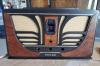
I just finished recapping all of the original capacitors and a few resistors that tested bad. The speaker started to make this weird crackling sound after I had replaced the 25uf electrolytic. At that time that was the only capacitor I had replaced. Now after a year or two I have goten around to recapping it hoping that it was just a issue with the fact that it started only after I had replaced it but when I powered it up for the first time again after repairing it I hooked up my variac and dim bulb. The set powered up with the bulb glowing dim at power up then another small flash from the rectifier and then after that the bulb went completely dark but then it started to glow again and at the same time the speaker was making this crackling noise and the bulb was slowly getting brighter. With the volume all the way down its still crackling and there is zero hum at any volume.
I am going to replace the 6F6 tube and hope that's the problem but im going to have to wait for it to get here but ill give an update once it arrives.
If I touch the top of the 1st audio tube the humming comes back and the volume also changes the volume of the humming. Im going to clean the some of the pin sockets and pins for the tubes to see if that does anything in the mean time until the tube arrives.
One thing to be cautious about is that the negative lead of the 25mfd electrolytic should not be connected to ground. It must be connected to the center tap of the power transformer.
I put the negative end of the 25uf to the original negative point that is on the cardboard insulation.
I had some help with it a while back when I was just getting into radios and Jack Saunders was helping me out a bit and he told me to put the negative end there.
The positive end is on the old terminal that was coming out from the bottom (positive) of the original can cap. The 10k resistor and one of the speaker wires is connected to that terminal as well and another wire. I re-soldered all of the connections on that terminal where everything is connected just in case when I was doing it a while back I didn't make it a cold solder joint but that wasn't the issue.
Couple of ideas:
Run the radio without the 6F6. There should be no noise. If you hear crackling, the bypass cap between the 6F6 plate and cathode is bad.
If you have a 6V6 or 6K6 you can temporarily try them in place of the F6. Bias will be wrong, but the radio will play.
If you still have the noise, unplug the other tubes but leave the output tube in place. If you still have crackling, then there is an issue with the output tube circuit (Tube, transformer, speaker voice coil and leads, cathode resistor (part of the power supply in your radio) or in the power supply (rectifier, filter cap, field coil, power transformer, etc.).
If the crackling goes away, then the issue is elsewhere in the radio.
Check for cold solder joints or a bad cap that you haven't changed.
"Do Justly, love Mercy and walk humbly with your God"- Micah 6:8
"Let us begin to do good"- St. Francis
I tested it with the 6K6 and 6V6 but it was still having the same issue.
I flipped the chassis over and the 10K resistor that I replaced was really hot.
Quick question. Is the terminal supposed to be floating in space? As I mentioned earlier the terminal that was coming out of the electro cap I cut off to use as a terminal for the positive end of the electrolytic. Is it supposed to be touching the old metal cap still or no?
The speaker was having this issue before I had replaced the 25uf where if I left the chassis flat like normal the speaker would make the crackling noise it is now but if I were to put it up-right it would sound normal again. but after I replaced the 25uf it no longer went back to normal at any orientation.
Also I removed all the tubes and left the output in and there was crackling still.
As long as the new filter cap isn't connected across the old one, or the old one has been gutted, there should not be an issue. I'm not sure how it could be making crackling noises with the tubes removed, I take it that you mean the cracking is coming from somewhere other then out of the speaker? It could be arcing, or it could be a resistor breaking down.
Regards
Arran
When I was testing to see if any B+ was getting past the 10K resistor I noticed that the dim bulb wasn't really going dim and I see smoke pouring out of the audio output transformer...
Anyone know where I can find a replacement that's the same size and values on mouser..?
Ok so I have narrowed it down to the 6F6 tube and the part No. 43 resistor strip thing causing my 10K resistor to get crazy hot. Do I wire 3 resistors in series and somehow connect all the wires and stuff on it or do I somehow put a terminal strip on them. How would I do that?
I'll probably look up a video on how to replace a resistor strip.
If none of this works I am still a bit new to the radio stuff and I would genuinely have no clue what to do after that or to just give up on it sense its already costed me a lot of money and just move on to my other "simplistic" ones.
Mr. Radio-Man Wrote: Anyone know where I can find a replacement that's the same size and values on mouser..?
You are very unlikely to find a new direct replacement in today's solid-state world. One possibility is to use a universal replacement transformer. Look at the Hammond line at Amplified Parts.
It appears you have a couple issues. One is the output transformer. Smoke doesn't always mean it's bad. You could measure the primary winding to see if it is not open. If it's open, I have been replacing these single-ended transformers with a Bogen T-72510. This one is a universal line transformer but should handle the output of your radio. I use either the blue or the black lead, whichever sounds better.
The issue with the "candohm" resistor is fairly simple to fix. It is a wirewound resistor with taps at the appropriate points. Before replacing it, make sure it needs to be replaced by measuring all the taps. Usually one or all the sections are open. My method is to pull the wire out of the metal case and use the terminals to mount new resistors. Use 10 watt resistors closest to the correct resistance in the schematic. You can also mount them on a terminal strip and move the wiring from the candohm to the terminal strip.
RodB Wrote: I have been replacing these single-ended transformers with a Bogen T-72510. This one is a universal line transformer but should handle the output of your radio.
Line transformers are very satisfactory in a lot of single-ended sets. Push-pull outputs generally need a universal output transformer, though I have heard of mimicking one with two single-ended transformers, which could be line transformers.
I began stocking NOS universal output transformers almost 40 years ago. Many came from a local parts jobber which was sold a few decades ago. The new owners sold a lot of inventory at fire sale prices. They needed to greatly downsize their inventory before moving to a smaller location. That sale is where I bought many parts which ended up in my Universal Shop Speaker and Dummy Field Coil. I have also been buying NOS universal output transformers at antique radio meets and hamfests for many years.
I now have a number of NOS universal output transformers from Thordarson, Stancor, Triad, and Merit. I am equipped for pretty much anything which I might need.
It depends on the wattage of heat dissipation required. For your radio:
Per the RCA Receiving Tube Manual, (RC14) the maximum output current of a 5Y4 is 125mA. Lets say 150 mA to build a little safety into it. Let's also say that the total B+ Load is 150 mA. Your Candohm, #43 is between Chassis Ground (Common) and the center tap pf the HV secondary feeding the rectifier plates, therefore the total 150mA B Current passes through this resistor.
The purpose of this resistor is to develop a negative bias voltage for various tubes, the highest voltage being for the 6F6 Output tube. Per the same RCA Receiving Tube Manual, the grid bias required for a 6F6 at 285V is -20V.
The total resistance of the Candohm is 245 Ohm. The total voltage drop across the resistor is 20V. Since current is constant through a series circuit, and Power (in Watts) = V X A, the power dissipated is 20V X 0.150A = 3W. So 3W flameproof metal film resistors would do the trick. 5W Wirewounds provide a higher margin of safety.
Now, in actuality, the total current load on the power supply is likely a lot lower than what I stated here before. If we look at actual tube load instead of maximum current capacity of the rectifier, the total cathode current(in mA) of all tubes added up is:
14 (6A8) + 8.7 (6K7) + 1 (6J5) + 1 (6F5) + 51(6F6) = 76mA. Since the 8uf cap also goes to chassis ground instead of to the center tap like the 25uF cap does, its ripple current has to be accounted for. Per the internet, the ripple is about 20mA. So we are at about 96mA. So round to 100 mA and the actual wattage dissipation is 2W.
On top pf that, note that the majority of the dissipation is across the 202 Ohm portion of the Candohm. The dissipation across the 8 Ohm and 35 Ohm resistors is much less than 3 watts.
So bottom line, use a 3W or 5W 200 Ohm resistor and at least a 1/2 Watt for the other two.
So it's your choice.
Did I overengineer this answer? Probably.
"Do Justly, love Mercy and walk humbly with your God"- Micah 6:8
"Let us begin to do good"- St. Francis