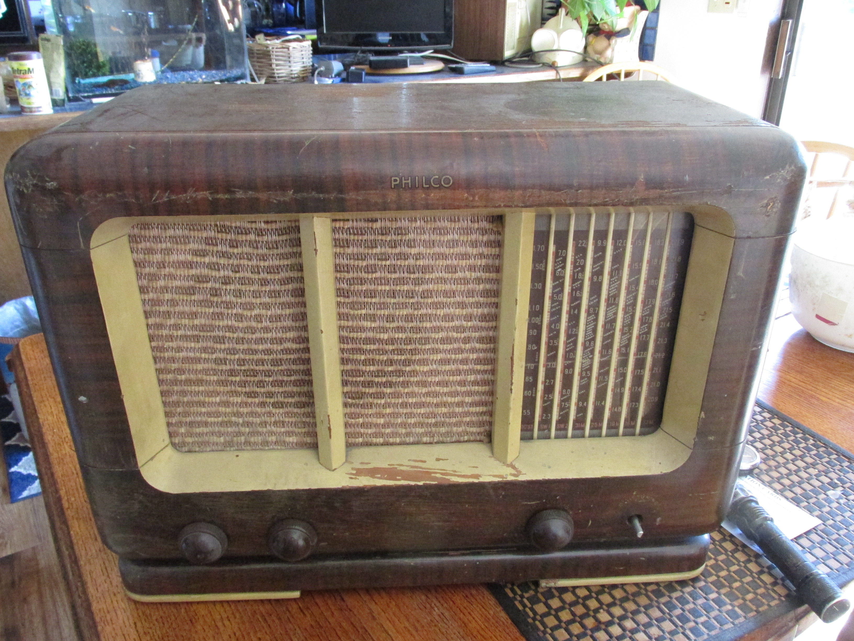
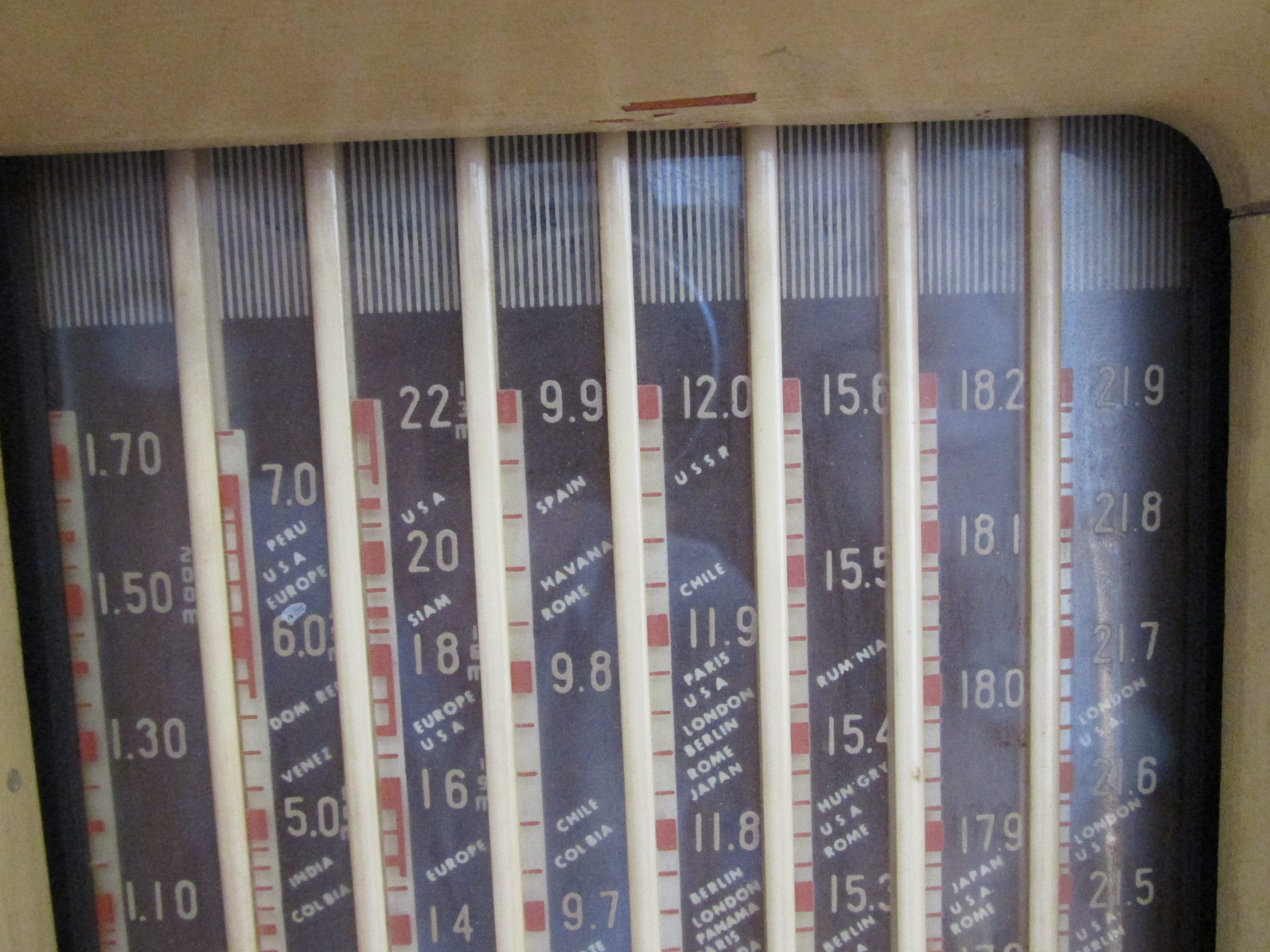
Just found this at an antique store. Intrigued me with the 7 sw and bc band. I cant find schematics anywhere. Only 1 thread here
from 15 years ago with no real information.
Any one have a schematic? or other info?
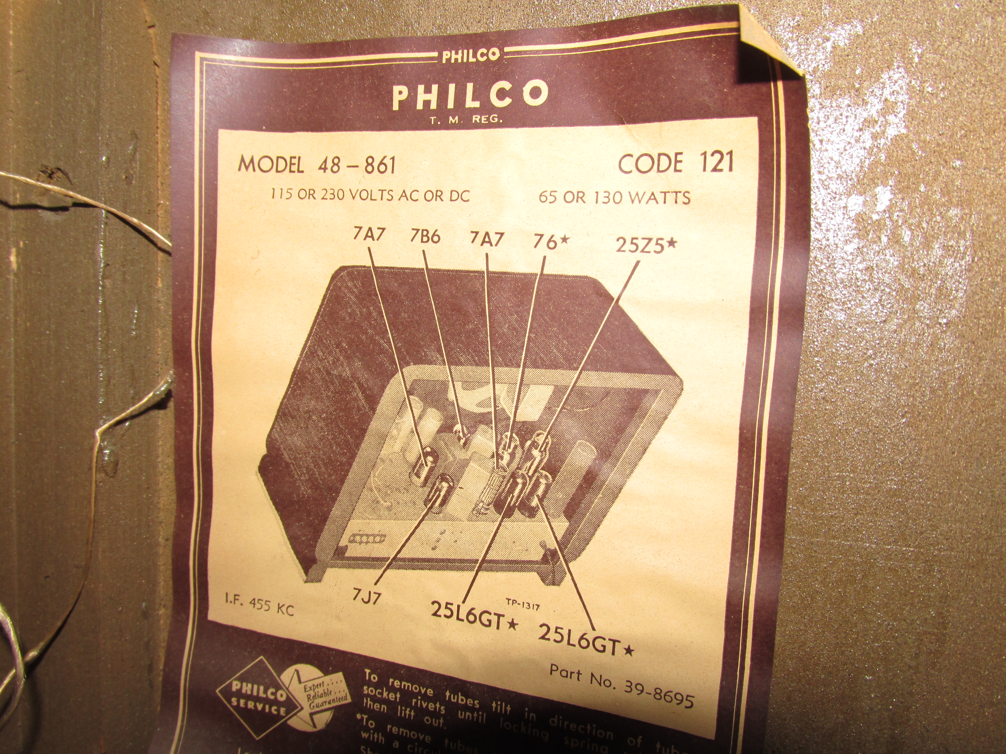
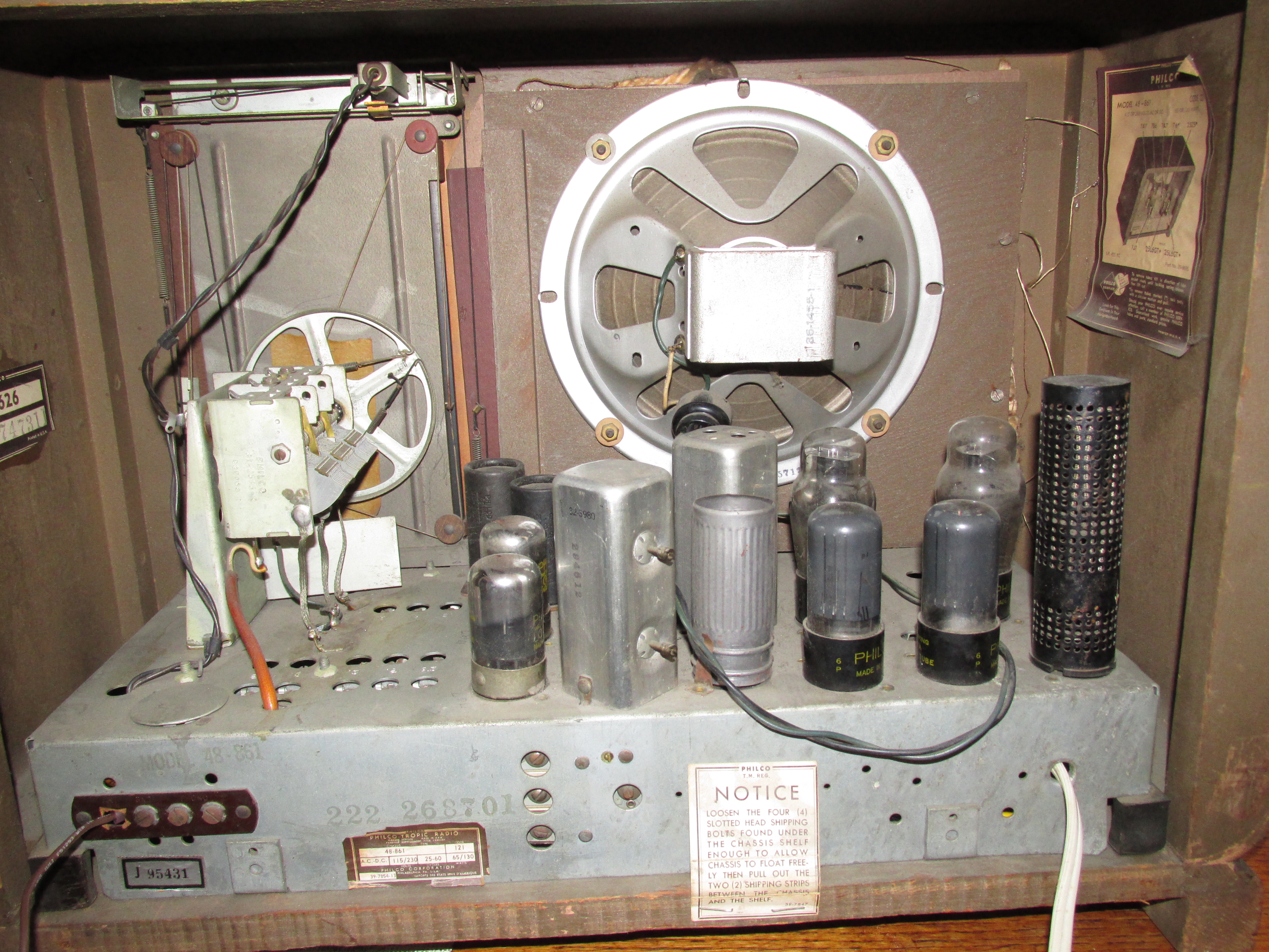
That looks like one of the post war Tropic models, which were intended for export. The 48-861 model number indicates that it was a U.S built set, Philco Products of Canada sometimes made "clones" of the Tropic models for the Canadian market but those would have at two digit model number. In looking closer it has a paper label on the chassis that says "Philco Tropic".
Regards
Arran
(This post was last modified: 09-07-2026, 06:08 PM by Arran.)
I tested all the tubes and look good!! I took out the ballast and tested to schematics ( thank you ), ohmed out fine. Fascinating, a curtain burner in a tube. lol
I dim bulbed set and looked ok. So i turned on, but no sound. Nothing.
Im guessing dead caps. Never did a non transformer radio so this will be interesting.
For a radio that old most experienced restorers will replace all electrolytic and wax-paper caps before doing anything else. I do - I stock a full range of plastic-dielectric caps (all 630 volt) to replace wax-paper caps, and a wide range of electrolytics.
The ballast is probably still good because it's main function is to drop the line voltage down for the tube heaters, especially if the set is used in places with 230-240 line voltage. So on 120 volts the ballast only has to drop 13.5 volts, as well as powering the pilot lamp bulb. With regard to the wiring did they use rubber/gutta perch covered wire or did they use the more modern vinyl wire? I have a Canadian model with a similar chassis called a 55T, also with 8 tubes, but it's an AC only transformer set with 6.3 volt tubes, the front end circuitry appears to be the same, the difference is that the 55T uses a pair of #42s and a type #80.
Regards
Arran
I have not worked on one of these, but other than the 115V / 220V Ballast, the set is straightforward. Looking at the schematic, there appears to be 2 ways to install the ballast. I would think that there are 2 notches in the octal socket for the ballast; one position for 115V operation, one for 230V (or whatever) operation. Looking at the schematic for the radio and for the ballast, in the 115V position, no current goes through the resistance element in the ballast. For 120V, all current goes through jumpers. See the following marked up schematic for what is jumped.
With the ballast in the 115V Position:
R103 is bypassed by a jumper in the ballast and full rectifier output is connected to R104.
120VAC is supplied by a jumper in the ballast to the rectifier plates (in parallel).
120V is supplied by a jumper in the ballast to the junction of R102 (in series with the heater string) and R101 (in series with the pilot light).
Do the following:
At the very least, replace the electrolytic filter caps. They usually open when dried out, causing a major hum but sometimes, they short, burning out resistors, tubes, etc.
Verify that the ballast is installed in the position for 115V operation.
Verify that when S100 (power switch) is closed, there is Zero Ohms across the switch.
With the switch closed, and ohming between both prongs of the power plug, you should find somewhere between 50 and 100 Ohms (with the tubes cold).
If this is not the case, check the tubes (The pin numbers are on the diagram, but for all of the loctal tubes, the heaters (filaments) are on pins 1 and 8. The 25L6 heaters are on pins 2 and 7, and the 25Z5 heater pins are 1 and 6, the 2 pins that are wider in diameter than the others.
If the heaters light but there is no sound, verify B+ to all points where B+ is expected, Ohm the speaker and the output transformer, the usual troubleshooting.
One other important thing: This is a warm chassis set (capacitor, 100K resistor or both connecting chassis to "Common" (B-, low side of heater string). To make things worse, the switch in the "common" lead, not the "high side". The following article from "Phil's Old Radios" explains the issue caused by this. https://antiqueradio.org/safety.htm
This is an interesting set. Instead of a power transformer selectable for 115 vs 220V AC and instead of using the 25Z5 as a voltage doubler in the 115V mode (Would work only on AC) and normal half wave rectifier in 220 VAC or DC Modes, the B+ is limited to about 110V. This set would totally rock with 200V or higher B+, especially with the 25L6s in Push Pull mode and the 8" speaker. As it is, the multiple bands for shortwave allow a high level of "band spread".
Keep us posted. Hope this helps
"Do Justly, love Mercy and walk humbly with your God"- Micah 6:8
"Let us begin to do good"- St. Francis
I did see the 2 choices for the ballast and the wring for each voltage. Interesting.
The wire seems ok. Vinyl i think but ok.
Thanks for ALL the info...will help a lot as i proceed
Lots to do...little time.
Will update.