Stromberg Carlson 1500 Squeal
Posts: 551
Threads: 88
Joined: Jun 2022
City: Marion
State, Province, Country: NY
Hello,
Working on the above. Caps all replaced as well as out of tolerance resistors. Radio plays but there is a bad squeal when a station is tuned in. When not on a station the squeal is not present. I have moved wires around a little but no change. Tubes all test good.
Thank you,
Dan
Posts: 1,797
Threads: 55
Joined: Feb 2015
City: Roseville, MN
Hi Dan,
https://www.nostalgiaair.org/models/Stro...o-1500.htm
Probably one of the hardest problems to solve. You work to get the thing to oscillate and heterodyne then it goes crazy. So the oscillation is probably there all the time but you can only hear it when the IF beats with it and produces the audible squeal. Because it's a feedback circuit and involves the IF and oscillator, the first thing to check is your work around the AVC, from the top of the volume control to the antenna. There's an rf pi filter (probably a couplette unit) on the secondary of the second IF and a 470pf mica(?) cap on pins 2 to 7 of the detector that can be checked out. Also the oscillator circuit component connections, there may be a cold solder joint. Did you clean the tube pins? Any connection that may be floating, like the leads of the AVC cap.
(This post was last modified: 10-10-2026, 12:00 PM by RodB.)
Posts: 18,427
Threads: 622
Joined: Oct 2011
City: Jackson
State, Province, Country: NJ
First one needs to understand, who it is squealing on.
People who do not drink, do not smoke, do not eat red meat will one day feel really stupid lying there and dying from nothing.
Posts: 1,797
Threads: 55
Joined: Feb 2015
City: Roseville, MN
Ignore the man behind the curtain!
Posts: 711
Threads: 46
Joined: Sep 2009
City: Lapeer, MI
State, Province, Country: USA
It wasn't me, I was somewhere else.
Courage will follow when Faith takes the lead.
Posts: 551
Threads: 88
Joined: Jun 2022
City: Marion
State, Province, Country: NY
Hi Rod, Man behind the curtain ignored.  I replaced the couplette with individual components after the squeal was discovered. Yes I am sure I did it correctly. I will check my work again and replace the 470 pf cap and the 47 pf one as well while I'm at it.
A little more info. The part called Special NTC was actually a 5 watt 120 ohm resistor. It was way off so I replaced it with a 2 watt. Don't know why I chose a 2 watt. I think I got confused with the resistor across the pilot light. I measured the filament of a couple of the 12 volt tubes and noted there was only 10 volts. At this point the radio was playing without the squeal. I noticed that resistor was getting very hot. I did a little checking around and found that the Special NTC was a thermistor that could be replaced with a CL90. So I did that and that's when the squeal showed up. Now there is about 12.5 volts on the 12 volt tubes. I also replaced the selenium with a 1N4007 and stayed with the 27 ohm resistor.
BTW the pilot light flashes really bright on first power up. For now I bring it up slow so as not to burn out the bulb.
Another note is the radio is very noisy with static pretty much like all my AA5/6 radios. They are not nice to listen to so I don't. Probably has to do with my distance from radio stations.
I'll reply back when I get those caps replaced and sockets cleaned.
Dan
Posts: 1,797
Threads: 55
Joined: Feb 2015
City: Roseville, MN
Did you replace C12 with an X safety capacitor?
The CL90 will run hot, the resistor schematic symbol I haven't seen before but it's very descriptive.
I think the squeal is from the failure of the rf decoupling caps.
(This post was last modified: 10-11-2026, 10:42 AM by RodB.)
Posts: 1,418
Threads: 41
Joined: Jan 2014
City: Wellborn Florida
The selenium will drop voltage app 7 volts the 1N4007 drops the voltage only 7/10 of a volt have fun with math and ohms law. David
Posts: 551
Threads: 88
Joined: Jun 2022
City: Marion
State, Province, Country: NY
C12 was replaced with a .05 X cap. C3 and C8 have been replaced with silver mica. Still squeals. I noticed R14 (across pilot) was replaced with a 12K. I have to quit for the day. Tomorrow I will replace R14 with the correct 120 ohm.
Dan
Posts: 551
Threads: 88
Joined: Jun 2022
City: Marion
State, Province, Country: NY
An update. R14 has been replaced. I didn't expect it to cure the squeal and it didn't. I have replaced all the tubes one at a time with no change.
Posts: 551
Threads: 88
Joined: Jun 2022
City: Marion
State, Province, Country: NY
Another update. I redid the RF alignment and it helped a bit but not much. The antenna trimmer did not weaken or peak the signal. I unplugged all walwarts in my shop and that helped a little more. But still not gone. I have gone over my work several times and found no problems. I checked voltages and they see close. Some higher and some lower. What I did notice was 12BA6 next to the 12BE6 had 12.9 vac on the filament and the 12BE6 had 11.8 vac. Also the pilot only has 4.4 vac. These readings were from input voltage of 111 vac. Should't they all read close to 12 vac? At this point everything has been changed except 3 resistor which measure pretty close. Maybe my problem is just plain bad reception and house electronic noise.
(This post was last modified: 10-12-2026, 11:16 AM by dconant.)
Posts: 2,325
Threads: 23
Joined: Jul 2020
City: Greenlawn
State, Province, Country: NY
Dan, an interesting issue. A couple of things: - I assume that this is not happening to any other AA5 type radios in your collection, therefore it is not environmental.
- Are all tube shields in place? Considering the proximity of the RF stage to the Convertor stage I would think that the designers would have shielded one of those tubes.
- Lead dress is important here.
- I have often wondered about the disappearance of the markings on caps indicating "outside foil". I have heard many reasons such as "The design of the cap eliminates the need" to "There is an outside foil but they are too cheap to mark it". It may or may not be important in B+ bypass caps, but likely is important for coupling caps. In this radio, the only caps to worry about are C10, the one across the 50L6 plate to screen grid (outer foil to screen); C9, the audio interstage coupling cap (outer foil to plate of 1st AF); C5, the AVC filter cap (Outside foil to B- / Common Return) and C4 from the B- / Common Return to chassis (outside foil to chassis). NOTE: Ensure that C5 connects between AVC and B- / Common and not between AVC and Chassis!
- Does the frequency of the squeal change as you get closer to the desired station, especially does the frequency lower until you are dead on the frequency of the desired station? Does the squeal ever go away or does it "waver" in low frequency when the station is properly tuned in?
- It is common for the pilot light in many AA5 or AA6 radios to be very bright upon first powerup. That's why so many of them burn out. This phenomenon is due to the fact that the tube heaters have a much lower resistance when cold than when hot. For example, in a 150mA heater string which this, to get a 12V drop across a tube such as the 12AV6, 12BA6, or 12BE6, the hot resistance would be 80 Ohm. You will find the cold resistance to be much lower than that.
- The NTC (Negative Temperature Coefficient, sometimes referred to as a "Globar" resistor) resistor, R13 on the schematic, is not used in many radios of this type. It was likely Stromberg Carlson's idea of protecting the tubes, pilot light bulb or both. The pilot in many AA5 sets is across the tap of the heater of the 35Z5 or 35W4 rectifier. The section of the 35Z5 / 35W4 heater that is in parallel with pilot lamp exhibits the same cold resistance that other heaters do, so the bulb is less likely to burn out than if the bulb is bridged by a regular resistor like in your set. Therefore, the NTC resistor is needed even more so in this set to prevent burnout of the pilot. These resistors do run hot.
- The placement of the NTC resistor in the middle of the string puzzles me. It is always best to keep heater to cathode voltage differential as low as possible. In its current location, the 6BA6 heater is at least 20 V higher than it could be if the NTC resistor was located "at the top" pf the string, closest to the "hot" AC lead, where the 35Z5 / 35W4 would be. If I designed the set (and maybe thank God I didn't), I would have located the NTC resistor at "the top" of the heater string.
- Check the voltage across the filter caps. If the voltage across the second filter is too high, this may affect the gain of the various stages and may initiate oscillation. Try putting the selenium rectifier back in circuit, if it is good, to see if the issue goes away.
- It is interesting that you state that when the tube voltages were low, that the squeal was not there. Do you have a "Variac"? If so, bring the voltage up to the point where the radio starts to work. Note whether the squeal exists. Continue raising the voltage till the squeal starts, note the voltage, then back down till the squeal stops. Rinse and repeat.
Nowadays, AM reception is subject to noise that did not exist years ago. This includes: - Compact Fluorescent and LED lights
- Switching power supplies
- Computers, Wi-Fi, the "Internet of Things" (Wi-Fi thermostats, home control modules, smart speakers, etc.)
- Cellular service towers
- Remote read electric, gas and water meters
- Etc., etc., etc.
"Do Justly, love Mercy and walk humbly with your God"- Micah 6:8
"Let us begin to do good"- St. Francis
Best Regards,
MrFixr55
Posts: 551
Threads: 88
Joined: Jun 2022
City: Marion
State, Province, Country: NY
Hello MrFixr55. Thanks for taking the time to spell it out. I have copied your text to here and included my notes in red. Hopefully you see that. This radio is very noisy as are my other AA5/6 radios. The squeal is more like a screech than a squeal. Maybe the same thing.
Dan
- I assume that this is not happening to any other AA5 type radios in your collection, therefore it is not environmental. Not happening to others.
- Are all tube shields in place? Considering the proximity of the RF stage to the Convertor stage I would think that the designers would have shielded one of those tubes. I wondered about tube shields but there are none or provisions for any.
- Lead dress is important here. I have been moving wire around a bit. Did not need to disturb anyway.
- I have often wondered about the disappearance of the markings on caps indicating "outside foil". I have heard many reasons such as "The design of the cap eliminates the need" to "There is an outside foil but they are too cheap to mark it". It may or may not be important in B+ bypass caps, but likely is important for coupling caps. In this radio, the only caps to worry about are C10, the one across the 50L6 plate to screen grid (outer foil to screen); C9, the audio interstage coupling cap (outer foil to plate of 1st AF); C5, the AVC filter cap (Outside foil to B- / Common Return) and C4 from the B- / Common Return to chassis (outside foil to chassis). NOTE: Ensure that C5 connects between AVC and B- / Common and not between AVC and Chassis! I will see if the outside foil is where you say. That will take me a bit. I am not sure where C5 is in the radio but I think I know. It is to B-. The only cap to chassis is C4.
- Does the frequency of the squeal change as you get closer to the desired station, especially does the frequency lower until you are dead on the frequency of the desired station? Does the squeal ever go away or does it "waver" in low frequency when the station is properly tuned in? The squeal is always the same frequency and is only present when tuned to a station.
- It is common for the pilot light in many AA5 or AA6 radios to be very bright upon first powerup. That's why so many of them burn out. This phenomenon is due to the fact that the tube heaters have a much lower resistance when cold than when hot. For example, in a 150mA heater string which this, to get a 12V drop across a tube such as the 12AV6, 12BA6, or 12BE6, the hot resistance would be 80 Ohm. You will find the cold resistance to be much lower than that.
- The NTC (Negative Temperature Coefficient, sometimes referred to as a "Globar" resistor) resistor, R13 on the schematic, is not used in many radios of this type. It was likely Stromberg Carlson's idea of protecting the tubes, pilot light bulb or both. The pilot in many AA5 sets is across the tap of the heater of the 35Z5 or 35W4 rectifier. The section of the 35Z5 / 35W4 heater that is in parallel with pilot lamp exhibits the same cold resistance that other heaters do, so the bulb is less likely to burn out than if the bulb is bridged by a regular resistor like in your set. Therefore, the NTC resistor is needed even more so in this set to prevent burnout of the pilot. C13 is now a CL90. Is that ok? These resistors do run hot.
- The placement of the NTC resistor in the middle of the string puzzles me. It is always best to keep heater to cathode voltage differential as low as possible. In its current location, the 6BA6 heater is at least 20 V higher than it could be if the NTC resistor was located "at the top" pf the string, closest to the "hot" AC lead, where the 35Z5 / 35W4 would be. If I designed the set (and maybe thank God I didn't), I would have located the NTC resistor at "the top" of the heater string.
- Check the voltage across the filter caps. If the voltage across the second filter is too high, this may affect the gain of the various stages and may initiate oscillation. Voltage on first cap is 132 and second cap 84 with DVM with respect to B- schematic say 140 and 81. Try putting the selenium rectifier back in circuit, if it is good, to see if the issue goes away. I will give that a shot as it was still working when I got started.
- It is interesting that you state that when the tube voltages were low, that the squeal was not there. Do you have a "Variac"? If so, bring the voltage up to the point where the radio starts to work. Note whether the squeal exists. Continue raising the voltage till the squeal starts, note the voltage, then back down till the squeal stops. Rinse and repeat. This is what I did, I lowered the vac down to 48 volts slowly and that is where the squeal stopped and so did reception. I assume tubes are not conducting any more. Going slowly from cold squeal and reception start at 70 volts. Don't know what that tells you. I believe the trouble started when I replaced R13 (120 ohm 5 watt) with the CL90 but that may be just because before doing the CL90 the 12 BE and BA were at 10 volts or so.
Nowadays, AM reception is subject to noise that did not exist years ago. This includes:- Compact Fluorescent and LED lights
- Switching power supplies
- Computers, Wi-Fi, the "Internet of Things" (Wi-Fi thermostats, home control modules, smart speakers, etc.)
- Cellular service towers
- Remote read electric, gas and water meters
- Etc., etc., etc.
Posts: 551
Threads: 88
Joined: Jun 2022
City: Marion
State, Province, Country: NY
The selenium has been put back in. Squeal still there. Voltages on ECaps now 86 and 62.
Posts: 551
Threads: 88
Joined: Jun 2022
City: Marion
State, Province, Country: NY
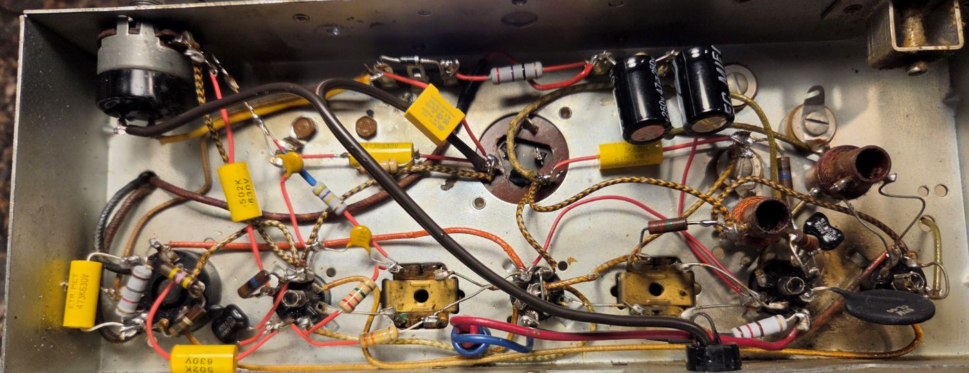
Here is the underside of the beast.
Users browsing this thread: 2 Guest(s)
|
|
Recent Posts
|
|
Preliminary work on wife's Silvertone 2014
|
| Hello roy,
that great news glad it worked out for you !!
Sincerely Richardradiorich — 10:50 PM |
|
Preliminary work on wife's Silvertone 2014
|
| Safety caps arrived today. Soldered one in and had a successful first power-up. No magic smoke escaped and it tunes in...glyphmon — 09:53 PM |
|
HiFi (Chifi) tube amp build - but my own design.
|
| Tim, you refer to “AK”. Is that Alaska or Atwater-Kent, or… JoeJoe Rossi — 11:49 AM |
|
Grundig 5088
|
| Skip,
you are back to this one?
As for fixing, Mark Oppat fixes vol. controls. Don't know about Grunding, but woul...morzh — 10:30 AM |
|
Stromberg Carlson 1500 Squeal
|
| I volunteer for a monthly Fixit Clinic in my county. All the fixers tell anyone who brings in a Keurig that it will prob...RodB — 10:24 AM |
|
Stromberg Carlson 1500 Squeal
|
| It's funny, a tale of 2 Keurigs. Friend's mom, an immigrant from Central America who had to leave school at the age of ...MrFixr55 — 09:01 AM |
|
Stromberg Carlson 1500 Squeal
|
| My biggest offender is our Keurig coffee maker. I make sure to keep it unplugged as it is still keeping the water warm w...dconant — 08:45 AM |
|
Grundig 5088
|
| All, Looking for a replacement volume control pot. or someone who can fix one..
Skipvecher — 09:17 PM |
|
HiFi (Chifi) tube amp build - but my own design.
|
| I did an experiment with these amps a month or so ago and I think they sound a lot better. I had been using a Douk pream...TV MAN — 03:08 PM |
|
Stromberg Carlson 1500 Squeal
|
| Have a touch lamp even off causes a problem up to 30 feet from the house have to unplug the monster. DavidDavid — 02:45 PM |
|
Who's Online
|
There are currently 2395 online users. [Complete List]
» 1 Member(s) | 2394 Guest(s)
|
|
|

|
 
|









