Posts: 711
Threads: 46
Joined: Sep 2009
City: Lapeer, MI
State, Province, Country: USA
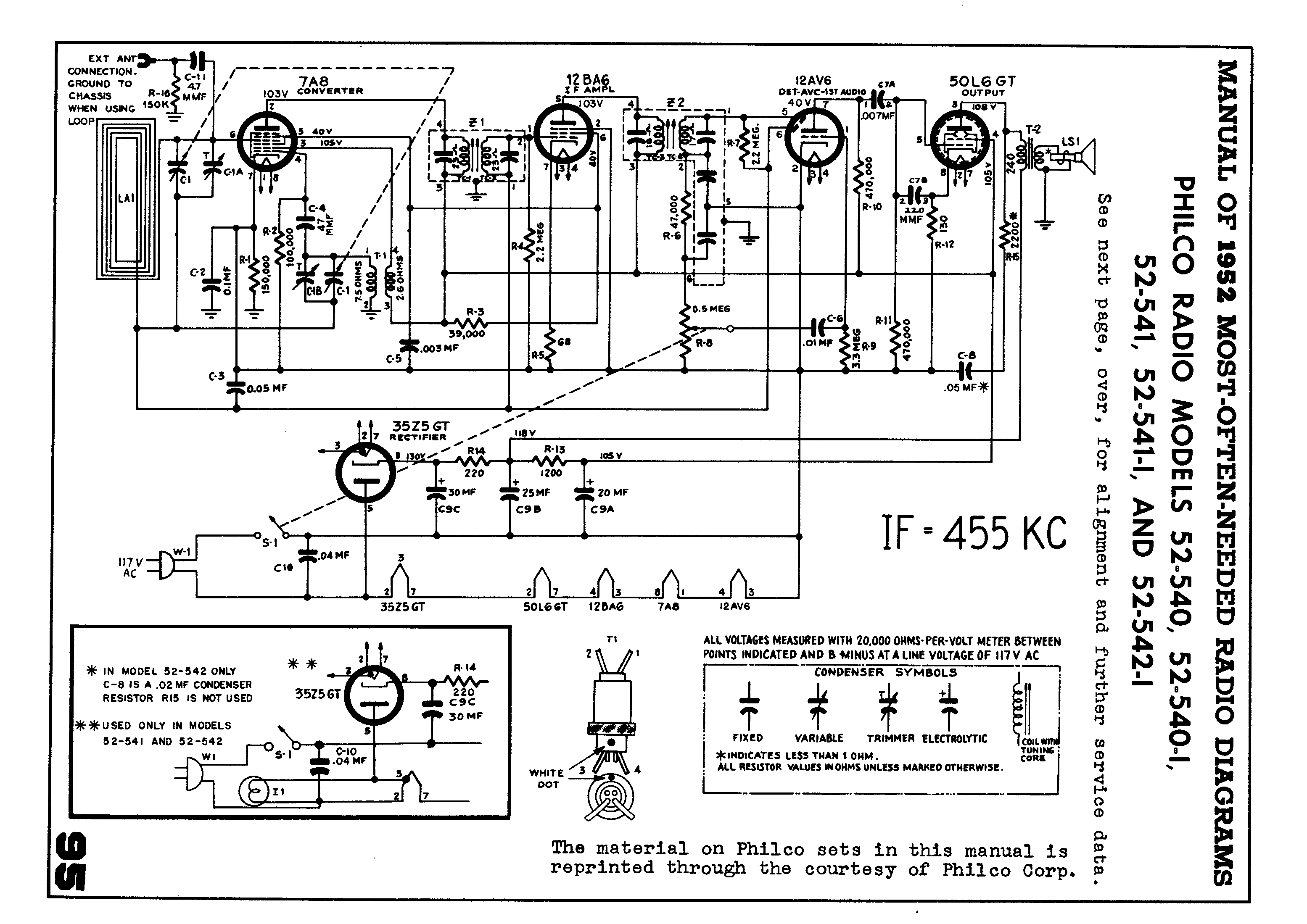
I'm nearly finished re-capping an re-resistoring when I see that the factory wiring of the 35Z5GT doesn't conform to the schematic. Filament pins 2 and 3 are wired in reverse. I'm presuming that this shouldn't make any difference, but it is so weird that the factory wired it this way. The chassis is untouched, all original Philco caps and shaggy carbon resistors. Even the tubes are the originals. Any thoughts? Thanks, Joe
Courage will follow when Faith takes the lead.
Posts: 1,418
Threads: 41
Joined: Jan 2014
City: Wellborn Florida
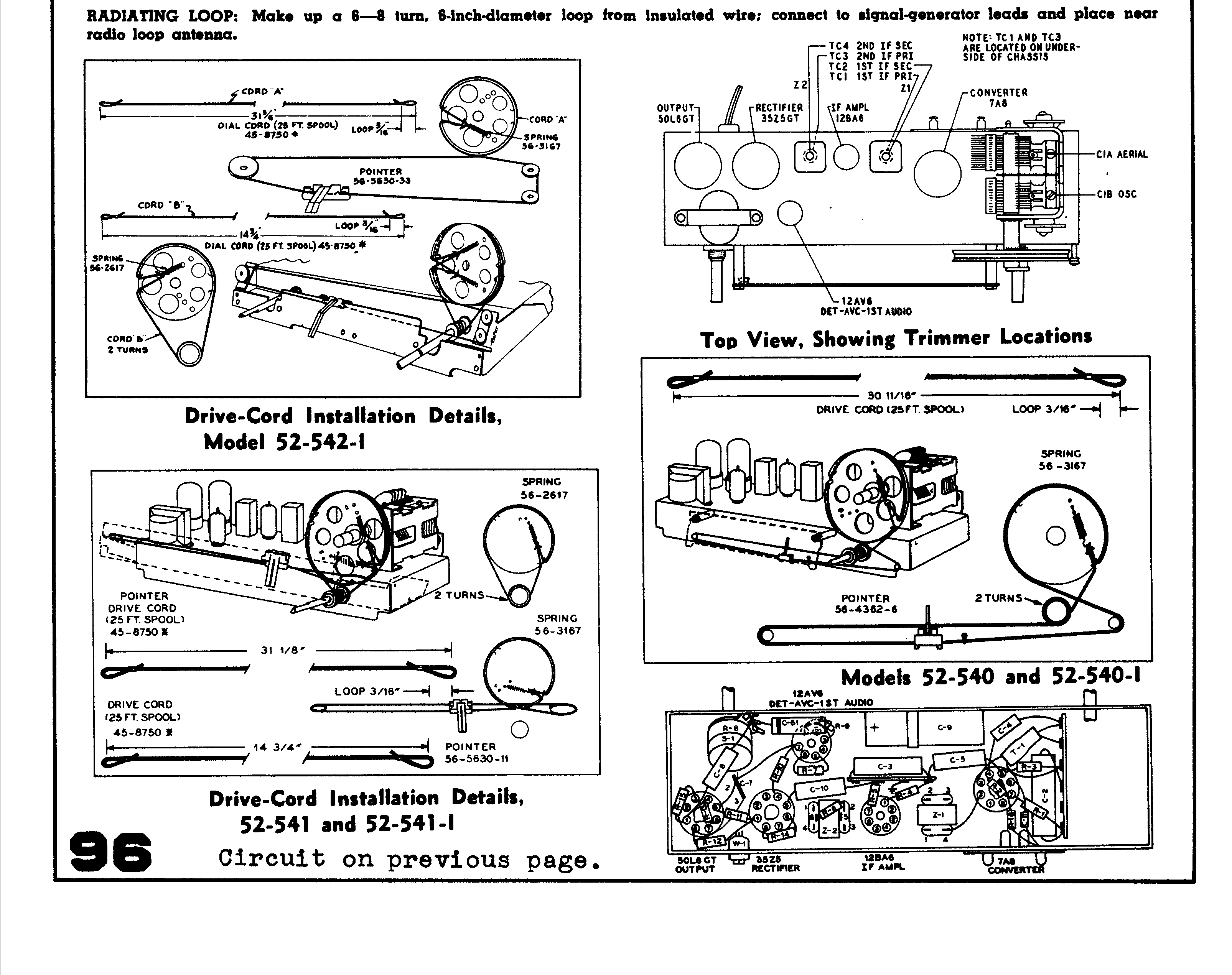
Some info from Beitmans the second page bottom right might help. David
Posts: 2,326
Threads: 23
Joined: Jul 2020
City: Greenlawn
State, Province, Country: NY
Does the pilot light light? If not, it is possible that someone swapped pins 2 and 3 because the section of the 35W4 between pins 2 and 3 burned outburned out. It was common during WWII to bypass pin 2 or jumper to pin 3 to return the radio to functionality as tubes may have been scarce during wartime. This supposedly was also done to radios belonging to servicemen stationed overseas where this tube was not common. Since this set was made before the Korean War, this may have been the reason for switching the connections.
Were all connections between pins 2 and 3 swapped or only the connection to the plate? Looking at the Philco schematic and the lower left window on the Breitman's schematic, it was common to connect the plate to the tap on the heater so that the heater acted as a fuse. The tube would blow if there was either a heater string short or a B+ short. A rather expensive fuse.
"Do Justly, love Mercy and walk humbly with your God"- Micah 6:8
"Let us begin to do good"- St. Francis
Best Regards,
MrFixr55
Posts: 711
Threads: 46
Joined: Sep 2009
City: Lapeer, MI
State, Province, Country: USA
MrFixr, Frankly, I haven't plugged the thing in yet. The resistance measurements haven't been close enough to trust. The Beitmans schematic above isn't the one for the version I have on the the bench (the Sams Photofact 154-10 is correct). I linked a portion of that one in my first post. This radio is a code 122 Run 1 radio where they use a 35L6 instead of the 50L6 and stick a "tube saver" thermistor between the filaments of the 35L6 and the 12BA6. I've determined that the thermistor has gone bad. I subbed a 50L6 and bypassed the thermistor and the filament ohms measurements have dropped in place. The thermistor measures 1.7K, but I have no idea what it should measure cold. My mind is a bit muddled but I will get back to this probably tomorrow morning. Thanks for the insight, Joe
Courage will follow when Faith takes the lead.









