Posts: 555
Threads: 89
Joined: Jun 2022
City: Marion
State, Province, Country: NY
Hello,
I am in need of a schematic for this radio. Mine has the three separate circular tube shields and a shadow meter also has a four wire condenser filter bank instead of the three wire. One speaker in a cathedral cabinet. The schematics I have (code 121 and 221) do not quite match my radio. The radio has a few cut wires and resistors hanging in the breeze. Anyone have the 125 schematic?
Thanks,
Dan
Posts: 555
Threads: 89
Joined: Jun 2022
City: Marion
State, Province, Country: NY
I noticed on the code 121 schematic the center tap for the 6 volt winding and hv winding are tied together. Is this correct?
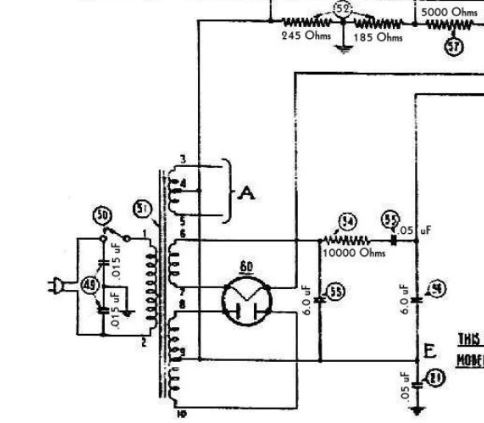
And life just keeps getting more complicated.
Posts: 1,799
Threads: 55
Joined: Feb 2015
City: Roseville, MN
Looks like that might be the B- buss, so that would be correct.
Posts: 555
Threads: 89
Joined: Jun 2022
City: Marion
State, Province, Country: NY
Really Rod? I know you would not steer me wrong but AI say this is a short circuit? What if I moved the 6 volt center tap to chassis ground. I agree the HV center tap is the B minus buss.
Reason I am questioning this is because I took the power trans out to replace the ratty wire and some how I forgot to note where the 6 volt center tap connected. Dang I hate when that happens.
Dan
And life just keeps getting more complicated.
Posts: 1,799
Threads: 55
Joined: Feb 2015
City: Roseville, MN
This might be one of those cases where it's a ground to an AC voltage and B- to DC.
Posts: 2,328
Threads: 23
Joined: Jul 2020
City: Greenlawn
State, Province, Country: NY
Technically, that's C-. B- is chassis ground. The resistor between chassis ground and the HV center tap makes the HV center tap the most negative point in the set. You would note that grid bias resistor to the output stage ties to this point. other grid bias resistors tie to resistor taps between this point and chassis ground. On many (or most) pre WWII radios, this scheme was used to generate bias voltages for various tubes, especially the Output stage but the 1st AF stage also.
It is legit to tie the heater center tap to this point as long as no other point in the heater circuit is tied to chassis ground. There was a theory that the heater be kept negative with respect to the cathode. Can't remember the reason why, but this practice was eventually abandoned when center taps were abandoned. Back in the day of directly heated tubes like 71s, 45s, 47s, 2A3s, etc., the center tap was important to reduce the hum levels when these filamentary cathodes were powered by AC. The center tap of the heater winding was where the cathode bias resistor was connected to in some late 1920s - early 1930s sets. In other sets, the center tap was to chassis ground and the grid bias resistor, or interstage transformer center tap connected to the HV secondary center tap.
BTW, AI is about as correct as the internet is. It is also the Wild West. AI is only as good as its source material.
Hope this helps
"Do Justly, love Mercy and walk humbly with your God"- Micah 6:8
"Let us begin to do good"- St. Francis
Best Regards,
MrFixr55







